1
4. Siting The Appliance
4.1 THE APPLIANCE MAY BE INSTALLED IN ANY ROOM
ALTHOUGH PARTICULAR ATTENTION IS DRAWN TO THE
REQUIREMENTS OF THE CURRENT I.E.E. WIRING REGULATIONS
AND, IN SCOTLAND, THE ELECTRICAL PROVISIONS OF THE
BUILDING REGULATIONS APPLICABLE IN SCOTLAND, WITH
RESPECT TO THE INSTALLATION OF APPLIANCES IN ROOMS
CONTAINING BATHS OR SHOWERS.
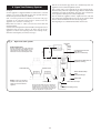
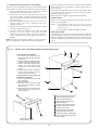
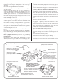
Installation
Service
Above the appliance
450 mm
10 mm
In front
600 mm
600 mm
5 mm
5 mm
300 mm
5 mm
Right side
Left side
4.7 The appliance can be installed in a cupboard to be used for
airing clothes provided that the requirements of BS 6798 and BS
5440:2 are strictly followed.
4.8 The airing space must be separated from the boiler space by
a perforated non-combustible partition. Expanded metal or rigid
wire mesh are acceptable provided that the major dimension is
less than 13mm. See BS 6798:1987.
4.9 No combustible surface must be within 75mm of the casing.
See BS476:4.
4.10 The distance between the inner face of a cupboard door
and the cabinet front should not be less than 75mm.
4.11 Always consider the possible need to disconnect the pipes
from the appliance after installation.
4.12 The appliance has a vertical flue option. Refer to Section 5c.
4.13 L.P.G. Installation: The appliance shall not be installed in a
room or internal space below ground level when it is intended for
use with L.P.G. This does not preclude the installation into rooms
which are basements with respect to one side of the building but
open to ground level on the opposite side.
WHERE A ROOM SEALED APPLIANCE IS INSTALLED IN A ROOM
CONTAINING A BATH OR SHOWER, ANY ELECTRICAL SWITCH OR
APPLIANCE CONTROL USING MAINS ELECTRICITY MUST NOT BE
ABLE TO BE TOUCHED BY A PERSON USING THE BATH OR
SHOWER.
4.2 The appliance is not suitable for external installation.
4.3 The appliance is floor standing, the floor must be firm and
level. Special floor protection is not required.
4.4 The floor must be capable of supporting the weight of the
appliance. Refer to Section 3 Table 5.
4.5 If the appliance is to be fitted in a timber framed building
refer to the British Gas publication “Guide for Gas Installations in
Timber Framed Housing”.
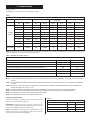
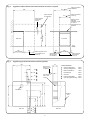
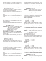
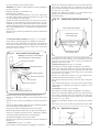
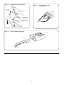
4.6 The following clearances must be available for installation
and for servicing, (See Fig. 2).
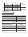
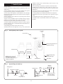
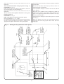
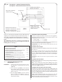
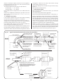
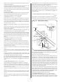
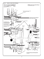
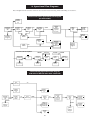
Fig. 4. Siting of the flue terminal.
TERMINAL POSITION
MINIMUM SITING DIMENSIONS FOR POSITIONING THE BALANCED
FLUE TERMINAL
A
G
D
BC
L
HI
L
F
A
K
F
K
E
F
J
G
M
A– directly below an openable window or
other opening e.g. air brick.
B– Below gutters, soil pipes or drain pipes.
C– Below eaves.
D– Below balconies or car port roof.
E– From vertical drain pipes and soil pipes.
F– From internal or external corners.
G– Above ground, roof or balcony level.
H– From a surface facing a terminal.
I– From a terminal facing a terminal
J– From an opening in a car port (e.g. door
window) into dwelling.
K– Vertically from a terminal on the same
wall.
L– Horizontally from a terminal on the same
wall.
M– From door, window or air vent (achieve
where possible).
MIN. DISTANCE
300 mm (12 in.)
75 mm (3 in.)
25 mm (1 in.)
25 mm (1 in.)
25 mm (1 in.)
25 mm (1 in.)
300 mm (12 in.)
600 mm (24 in.)
1200 mm (47 in.)
1200 mm (47 in.)
150 mm (6 in.)
300 mm (12 in.)
150 mm (6 in.)
5a.6 The terminal guard must be evenly spaced about the flue
terminal and fixed to the wall using plated screws
5a.7 In certain weather conditions a terminal may steam and
siting where this could cause a nuisance should be avoided.
5a.8 Take care to ensure that combustion products do not enter
ventilated roof voids.
NB. For siting the Vertical Balanced Flue Terminal refer to the
Installation and Servicing Instructions packed with the vertical flue kit.
5a. Flue Terminal Position
Note: Some flue options must have fitted a flue restrictor ring of
the correct size. For more information refer to Section 11.3
page 20 and Fig. 24.
5a.1 The flue must be installed as specified by BS 5440:Part 1.
5a.2 TERMINAL POSITION. See Fig. 4.
5a.3 The terminal must not cause an obstruction nor the
discharge a nuisance.
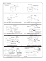
5b. Flue Options
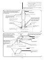
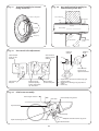
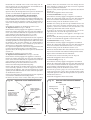
5a.4 If the terminal is fitted within 850mm of a plastic or painted
gutter or within 450mm of painted eaves then an aluminium
shield at least 750mm long should be fitted to the underside of
the gutter or painted surface.
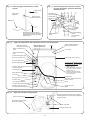
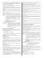
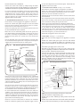
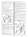
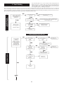
See Fig. 5.
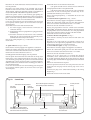
Two standard flue kits are available for the appliance:
5b.1 STANDARD HORIZONTAL REAR FLUE KIT.
See Fig. 5 Frame 1.
The maximum flue length when measured from the REAR of the
appliance casing is 500 mm. The flue will project horizontally
only from the rear of the appliance.
5a.5 If a terminal is fitted less than 2 metres above a surface to
which people have access then a guard must be fitted. Refer to
Section 2, Item 2.9.
8