1
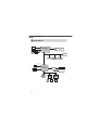
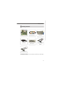
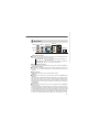
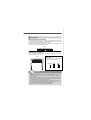
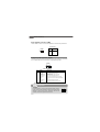
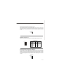
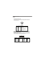
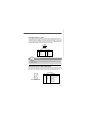
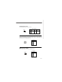
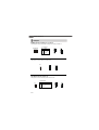
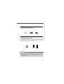
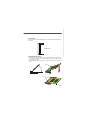
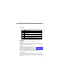
Fuzzy LX800 / LX800D
Series
MS-9801 (V1.X) Mainboard
G52-98011X1
i
Copyright Notice
Th e material in this d ocument is the in tellectual p rop erty of MICRO-STAR
INTERNATIONAL. We take every care in the preparation of this document, but no
guarantee is given as to the correctness of its contents. Our products are under
continual improvement and we reserve the right to make changes without notice.
Trademarks
All trademarks are the properties of their respective owners.
Intel® and Pentium® are registered trademarks of Intel Corporation.
AMD, Athlon™, Athlon™ XP, Thoroughbred™, and Duron™ are registered trademarks of AMD Corporation.
NVIDIA, the NVIDIA logo, DualNet, and nForce are registered trademarks or trademarks of NVIDIA Corporation in the United States and/or other countries.
PS/2 and OS ®/2 are registered trademarks of International Business Machines
Corporation.
Windows® 95/98/2000/NT/XP are registered trademarks of Microsoft Corporation.
Netware® is a registered trademark of Novell, Inc.
Award® is a registered trademark of Phoenix Technologies Ltd.
AMI® is a registered trademark of American Megatrends Inc.
Revision History
Revision
V1.0
Revision History
First release
Date
June 2007
Technical Support
If a problem arises with your system and no solution can be obtained from the user’s
manual, please contact your place of purchase or local distributor. Alternatively,
please try the following help resources for further guidance.
Visit the MSI website for FAQ, technical guide, BIOS updates, driver updates,
an d oth er in forma tion : htt p:// glob al.m si.com.tw /ind ex.p hp?
func=faqIndex
Contact our technical staff at: http://support.msi.com.tw/
ii
Safety Instructions
1.
Always read the safety instructions carefully.
2.
Keep this User’s Manual for future reference.
3.
Keep this equipment away from humidity.
4.
Lay this equipment on a reliable flat surface before setting it up.
5.
The openings on the enclosure are for air convection hence protects the equipment from overheating. DO NOT COVER THE OPENINGS.
6.
Make sure the voltage of the power source and adjust properly 110/220V before connecting the equipment to the power inlet.
7.
Place the power cord such a way that people can not step on it. Do not place
anything over the power cord.
8.
Always Unplug the Power Cord before inserting any add-on card or module.
9.
All cautions and warnings on the equipment should be noted.
10. Never pour any liquid into the opening that could damage or cause electrical
shock.
11. If any of the following situations arises, get the equipment checked by service
personnel:
† The power cord or plug is damaged.
† Liquid has penetrated into the equipment.
† The equipment has been exposed to moisture.
† The equipment does not work well or you can not get it work according to
User’s Manual.
† The equipment has dropped and damaged.
† The equipment has obvious sign of breakage.
12. DO NOT LEAVE THIS EQUIPMENT IN AN ENVIRONMENT UNCONDITIONED, STORAGE TEMPERATURE ABOVE 600 C (1400F), IT MAY DAMAGE THE EQUIPMENT.
CAUTION: Dan g er of exp losion if b attery is in correctl y rep laced .
Replace on ly with the same or equivalent type recommen ded by the
manufacturer.
iii
FCC-B Radio Frequency Interference Statement
Th is eq u ip men t h as been
tested and found to comply
with the limits for a Class B
digital device, pursuant to Part
15 of the FCC Rules. These limits are designed to provide reasonable protection
against harmful interference in a residential installation. This equipment generates,
uses and can radiate radio frequency energy and, if not installed and used in accordance with the instructions, may cause harmful interference to radio communications.
However, there is no guarantee that interference will not occur in a particular
installation. If this equipment does cause harmful interference to radio or television
reception, which can be determined by turning the equipment off and on, the user is
encouraged to try to correct the interference by one or more of the measures listed
bel ow.
† Reorient or relocate the receiving antenna.
† Increase the separation between the equipment and receiver.
† Connect the equipment into an outlet on a circuit different from that to
which the receiver is connected.
† Consult the dealer or an experienced radio/television technician for help.
Notice 1
The changes or modifications not expressly approved by the party responsible for
compliance could void the user’s authority to operate the equipment.
Notice 2
Shielded interface cables and A.C. power cord, if any, must be used in order to
comply with the emission limits.
VOIR LA NOTICE D’INSTALLATION AVANT DE RACCORDER AU RESEAU.
Micro-Star International
MS-9801
This device complies with Part 15 of the FCC Rules. Operation is subject to the
following two conditions:
(1) this device may not cause harmful interference, and
(2) this device must accept any interference received, including interference that
may cause undesired operation.
iv
WEEE (Waste Electrical and Electronic Equipment) Statement
v
vi
vii
CONTENTS
Copyright Notice .................................................................................................... iii
Trademarks ............................................................................................................ iii
Revision History .................................................................................................... iii
Technical Support ................................................................................................. iii
Safety Instructions ................................................................................................ iii
FCC-B Radio Frequency Interference Statement .................................................... v
WEEE (Waste Electrical and Electronic Equipment) Statement ................................ v
Chapter 1 Getting Started .............................................................................. 1-1
Mainboard Specifications ............................................................................. 1-2
Block Diagram ............................................................................................... 1-4
Board Dimension .......................................................................................... 1-5
Mainboard Layout ........................................................................................ 1-6
Packing Contents ......................................................................................... 1-7
Chapter 2 Hardware Setup ............................................................................. 2-1
Quick Components Guide ............................................................................. 2-2
Memory ....................................................................................................... 2-3
Power Supply .............................................................................................. 2-4
Back Panel ................................................................................................... 2-7
Connectors .................................................................................................. 2-9
Jumpers ..................................................................................................... 2-16
Slots .......................................................................................................... 2-18
Chapter 3 BIOS Setup ...................................................................................... 3-1
Entering Setup ............................................................................................. 3-2
The Main Menu ............................................................................................. 3-4
Standard CMOS Features ............................................................................ 3-6
Advanced BIOS Features ............................................................................ 3-8
Advanced Chipset Features ...................................................................... 3-10
Integrated Peripherals ................................................................................ 3-12
Power Management Setup ......................................................................... 3-14
PNP/PCI Configurations .............................................................................. 3-16
Load Fail-Safe / Optimized Defaults ........................................................... 3-18
Set BIOS Password ................................................................................... 3-19
viii
Getting Started
Chapter 1
Getting Started
Thank you for choosing the Fuzzy LX800 / LX800D
Series (MS-9801 v1.X) Mini ITX mainboard from MSI.
Based on the innovative AMD® Geode CS5536 controllers for optimal system efficiency, the Fuzzy LX800
/ LX800D Series accommodates AMD® Geode LX700/
LX800/LX900 processors and supports two 184-pin
333/400 MHz DDR DIMM to provide the maximum of 2GB
memory capacity.
Noiseless, Fan less and low power consumption are
the advantageous of Fuzzy LX800 / LX800D Series.
Due to the IPC special application, Fuzzy LX800 /
LX800D Series also provid es two different power
SKUs: ATX power and DC-in for your customization.
1-1
MS-9801 Mainboard
Mainboard Specifications
Embedded Processor
- AMD® Geode LX700/LX800/LX900 x86/x87 Compatible Core 433/
500/600 MHz
- 481-terminal PBGA (Pl astic Ball Grid Array) With Intern al
Heatspreader
- 128K L2 cache
Chipset
- South Bridge: AMD® Geode CS5536 Companion Device
Memory Support
- DDR 333/400 SDRAM (2GB Max)
- 2 DDR DIMM slots (184pin / 2.5V)
Display
- AMD LX800 Integrated, Max Shared Memory to 64MB
- High Resolution CRT & TFT outputs
- Support Analog CRT output
- Dual Channel 24 bits LVDS Video Output
- Support RCA-Out & S-Video Out (640x480 in PAL and NTSC
mode)
LAN
- 2 Realtek RTL8110SC Chipset, support 10/100/1000Mbps
- Support Wake-on-Lan
Audio
- Realtek® Audio 2 channels AC’97 codec
IDE
- 1 IDE Channel with ATA 100/66/33
- 1 CF connector Shared With 1 IDE Channel, CF only support in
Master mode.
-CF supports Slave mode only by using ATA33 IDE cable.
Power Connector
- 1 ATX 20pin connector for system power (for LX800)
- 1 4-pin Internal DC Input Connector (for LX800D)
- 1 Din4 12V DC-in Connector (for LX800D)
1-2
Getting Started
Connectors
Back Panel
- 2 RJ-45 LAN jacks
- 2 USB 2.0 ports
- 1 D-Sub VGA connector
- 1 serial port
- 1 PS2 keyboard/mouse port
- 1 Line-In/Line-Out/Mic-In stacked audio jack
- 1 TV out
- 1 S-Video out
Onboard Pinheaders
- 1 USB 2.0 pinheader (2 ports)
- 1 parallel port pinheader
- 1 front audio pinheader
- 1 LVDS connector
- 3 RS232 pinheaders
- 1 DIO connector
- 1 SMBUS connector
- 1 Chassis Intrusion Switch connector
- 1 CD-in connector
- 1 TV out pinheader
Slots
- 1 Mini PCI Socket
- 1 PCI 2.2 compliant slot support 3.3V Only
Form Factor
- Mini ITX
Mounting
- 4 mounting holes
Environmental
Operating Temperature
- Temperature: -10oC ~ 70oC
- Humidity: 85% RH
Storage Temperature
- Temperature: -20oC ~ 80oC
- Humidity: 25% ~ 90% RH
1-3
MS-9801 Mainboard
Block Diagram
CRT
CRT
DR GB
Bus
LVD S
M omory
Bus
CPU
AMD Geode LX
Processor
DD R DR AM
D IM M 400D DR
PCI Bus 33MH z
PCI Slot
Mini -PCI
ID E
Prim ary IDE
ATA-100
CF
USB2.0
Co mp a nio n
D evice
A M D CS 5 5 36
AC 97
Internal Audio
AC' 97
Audio
External Audio
Internal X2
6W Amplifer
LPC Bus
CO M1
CO M2
1-4
C OM3
C OM4
Getting Started
Board Dimension
Unit : mm
1-5
MS-9801 Mainboard
Mainboard Layout
JAMP1
IDE1
JCF_SEL
BIOS
COM2 COM3 COM 4
F_USB1
IRDA
JFP1
J1
BATT
+
Audio
Codec
Top : mouse
Bottom: keyboard
J7
J4
J2
J3
J5
J6
JLPT1
JCI1
T:Line-In
M:Line- Out
B:Mic-In
JCD1
JAUD1
CF1
J66EN_SEL1
AMD Geode
CS5536
JLVDS1
SYSFAN1
JTV1
Top: TV Out
Bottom: S-Video Out
PRJK1
(optional
SKU for
DC input)
ATX1
DIMM1
DIMM2
JLAN1
AMD Geode
ALXD800EEXJ2VD
MINI PCI1
Top: LAN jack
Bottom: USB ports
JPW1
(optional
SKU for
DC input)
JPWR1 (optional SKU for DC input)
PCI1
JSMB1
Fuzzy LX800 / LX800D Series (MS-9801 v1.X) Mini ITX
Mainboard
1-6
(optional SKU for ATX power)
Top: Serial Port
Bottom: VGA Port
Getting Started
Packing Contents
MSI motherboard
MSI Driver/Utility CD
User’s Guide
Back IO Shield
Standard Cable for
IDE Devices
Parallel and COM Port
Bracket
2 COM Ports Bracket
* The pictures are for reference only. Your packing contents may vary depending on
the model you purchased.
1-7
Hardware Setup
Chapter 2
Hardware Setup
This chapter provides you with the information about
hardware setup procedures. While doing the installation,
be careful in holding the components and follow the
installation procedures. For some components, if you
install in the wrong orientation, the components will not
work properly.
Use a grounded wrist strap before handling computer
comp onen ts. Static el ectricity may damag e th e
components.
2-1
MS-9801 Mainboard
Quick Components Guide
JLVDS1,
p.2-14
JAMP1,
p.2-10
JAUD1,
p.2-10
J2~J7,
p.2-16
COM2~4,
p.2-13
JCI1,
p.2-10
JLPT1,
p.2-11
JCD1,
p.2-14
CLR_CMOS1, IDE1,
p.2-17
p.2-9
J1,
p.2-11
JCF_SEL,
p.2-8
F_USB1,
p.2-13
IRDA,
p.2-15
JFP1,
p.2-12
CF1,
p.2-9
Back
Panel,
p.2-7
DIMM1,2,
p.2-3
J66EN_SEL1,
p.2-17
SYSFAN1,
p.2-11
ATX1,
p.2-4
JPWR1,
p.2-5
PRJK1,
p.2-4
JPW1,
p.2-5
JTV1,
p.2-15
2-2
MINIPCI1,
p.2-19
PCI1,
p.2-18
JSMB1,
p.2-15
Hardware Setup
Memory
The mainboard provides two 184-pin non-ECC DDR 333/400 DIMM slot and supports
up to 2GB system memory.
DDR
184-pin, 2.5V
40x2=80 pin
52x2=104 pin
Installing DDR Modules
1. The memory module has only one notch on the center and will only fit in the right
orientation.
2. Insert the memory module vertically into the DIMM slot. Then push it in until the
golden finger on the memory module is deeply inserted in the DIMM slot.
Important
You can barely see the golden finger if the memory module is properly inserted
in the DIMM slot.
3. The plastic clip at each side of the DIMM slot will automatically close.
Volt
Notch
2-3
MS-9801 Mainboard
Power Supply
ATX 20-Pin System Power Connector: ATX1(optional SKU for ATX
power)
This connector allows you to connect to an ATX power supply. To connect to the ATX
power supply, make sure the plug of the power supply is inserted in the proper
orientation and the pins are aligned. Then push down the power supply firmly into the
connector.
ATX1 Pin Definition
ATX1
11
20
1
10
PIN
SIGNAL
PIN
SIGNAL
1
2
3
4
5
6
7
8
9
3.3V
3.3V
GND
5V
GND
5V
GND
PW_OK
5V_SB
10
12V
11
12
13
14
15
16
17
18
19
20
3.3V
-12V
GND
PS_ON
GND
GND
GND
-5V
5V
5V
Din4 12V DC-in Connector: PRJK1 (optional SKU for external DCin)
This connector allows you to connect to an external DC12V power supply. To connect
to the DC12V power supply, make sure the plug of the power supply is inserted in the
proper orientation and the polarity of pins are matched.
PRJK1 Definition
4
3
2 1
2-4
Hole
SIGNAL
1
2
3
4
GND
GND
12V
12V
Hardware Setup
4-Pin Internal Power Connector: JPW1 (optional SKU for internal
DC-in)
This connector allows you to connect to an internal DC12V power supply. To connect
to the DC12V power supply, make sure the plug of the power supply is inserted in the
proper orientation and the polarity of pins are matched.
JPW 1 Pin Definition
JPW1
2
1
4
3
PIN
SIGNAL
1
2
3
4
GND
GND
12V
12V
Disk Drive Power: JPWR1 (optional SKU for DC input)
This connector delivers power to IDE devices.
JPWR1 Definition
4
3
2
1
Hole
SIGNAL
1
2
3
4
5V
GND
GND
12V
2-5
MS-9801 Mainboard
Power Consumption
Power Supply : LEMACS
Model : AX2-5300FB-2S(V)
AC INPUT : 115V230V 60/50Hz 9/5A
FUSE RATING : 6A/250V
DC OUTPUT : 300W
+5V 30A
+12V 12A
+3.3V 14A,
-5V 0.5A
-12V 0.5A
+5VSB 1.5A
+5V AND +3.3V TOTAL MAX : 150W
A. Playing DVD - Power DVD 7.0
Main Board +3.3V
Main Board +5V
Main Board 5VSB
Main Board +12V
Main Board Power Consumption
Measured Voltage
3.4054
5.0959
5.0808
11.762
Measured Amp.
0.713
0.037
0.067
0.584
Watts
2.4281
0.1885
0.3404
6.8690
9.8260
Measured Amp.
0.712
0.032
0.067
0.552
Watts
2.4246
0.1639
0.3404
6.4170
9.3459
Measured Voltage
3.3993
5.1177
5.0808
11.66
Measured Amp.
1.606
0.038
0.063
0.586
Watts
5.4593
0.1945
0.3201
6.8328
12.8066
Measured Voltage
3.4054
5.1238
5.0811
11.619
Measured Amp.
0.724
0.043
0.069
0.46
Watts
2.4655
0.2203
0.3506
5.3447
8.3812
Measured Voltage
0
0.3965
5.0615
0.0115
Measured Amp.
0
0
0.225
0
Watts
0.0000
0.0000
1.1388
0.0000
1.1388
B. Playing MP3 - Media Player
Main Board +3.3V
Main Board +5V
Main Board 5VSB
Main Board +12V
Main Board Power Consumption
Measured Voltage
3.4053
5.1219
5.0811
11.625
C. Running Network Application - Files Copy
Main Board +3.3V
Main Board +5V
Main Board 5VSB
Main Board +12V
Main Board Power Consumption
D. Idle
Main Board +3.3V
Main Board +5V
Main Board 5VSB
Main Board +12V
Main Board Power Consumption
E. S3 Mode
Main Board +3.3V
Main Board +5V
Main Board 5VSB
Main Board +12V
Main Board Power Consumption
2-6
Hardware Setup
Back Panel
Line-In
M ouse
Serial Port
RCA out
LAN Port
Line-Out
LAN Port
Mic-In
Keyboard
VGA Port
S-Videoout USB Ports
Audio Port Connectors
These audio connectors are used for audio devices. You can differentiate the color
of the audio jacks for different audio sound effects.
Blue audio jack - Line In is used for external CD player, tapeplayer or
other audio devices.
Green audio jack - Line Out, is a connector for speakers or headphones.
Pink audio jack - Mic In, is a connector for microphones.
Mouse/Keyboard Connector
The standard PS/2® mouse/keyboard DIN connector is for a PS/2® mouse/keyboard.
Serial Port Connector
The serial port is a 16550A high speed communications port that sends/ receives 16
bytes FIFOs. You can attach a serial mouse or other serial devices directly to the
connector.
VGA Connector
The DB15-pin female connector is provided for VGA monitors.
RCA Out
The RCA connector allows users to connect display devices for composite video
input/output.
Composite video, also called baseband video or RCA video, is the analog waveform
that conveys the image data in a conventional NTSC and PAL television signal.
Composite video con tains chrominance (hue and saturation) and luminance
(brightness) information, along with synchronization and blanking pulses, all together
in a single signal.
S-Video Out
The S-Video connector allows users to connect display devices for component
video input/output.
S-Video (Super-Video, sometimes referred to as Y/C Video, or component video) is
a video signal transmission in which the luminance signal and the chrominance signal
are transmitted separately to achieve superior picture clarity. The luminance signal
(Y) carries brightness information, which defines the black and white portion, and
the chrominance signal (C) carries color information, which defines hue and saturation.
An S-Video connection brings better video quality than a composite/RCA connection.
2-7
MS-9801 Mainboard
LAN (RJ-45) Jacks
The standard RJ-45 jacks are for connection
to Local Area Network (LAN). You can
connect network cables to them.
100M Cable Plug-in
1000M Cable Plug-in
Link Indicator
Le ft LED
Right LED
Active LED
100M/1000M Speed LED
Yellow
Green/Orange
No Transmission
OFF
OFF
Transition
Yellow(Blinking)
OFF
No Transmission
OFF
Green(Lighting)
Transition
Yellow(Blinking)
Green(Lighting)
No Transmission
OFF
Orange(Lighting)
Transition
Yellow(Blinking)
Orange(Lighting)
OFF
OFF
LED Color
10M Cable Plug-in
Activity Indicator
In S3/S4/S5 Standby State
USB Connectors
The OHCI (Open Host Controller Interface) Universal Serial Bus root is for attaching
USB devices such as keyboard, mouse, or other USB-compatible devices.
2-8
Hardware Setup
Connectors
ATA100 Hard Disk Connector: IDE1
The mainboard has a 32-bit Enhanced PCI IDE and Ultra DMA 33/66/100 controller that
provides PIO mode 0~4, Bus Master, and Ultra DMA 33/66/100 function. You can
connect hard disk drives, CD-ROM and other IDE devices.
The Ultra ATA100 interface boosts data transfer rates between the computer and the
hard drive up to 100 megabytes (MB) per second.
IDE1
Compact Flash Card Slot: CF1
This Compact Flash slot shares one channel of the IDE controller. You can install one
Compact Flash typeI / type II device.
CF1
CF Mode Selecting Jumper:
JCF_SEL1
This jumper is used to select Master/
Slave mode of the CF device.
JCF_SEL1
1
1
1
3
Master
3
Slave
Important
* The CF1 slot and the IDE1 connector shares and uses the same channel, CF1
and IDE1 can support up to 2 IDE devices without CF device or 1 IDE device
with 1 CF device.
* If you install two IDE devices, you must configure the second drive to Slave
mode by setting its jumper. Refer to the hard disk documentation supplied by
hard disk vendors for jumper setting instructions.
* If you install one IDE device with ATA100 IDE cable and one CF device, you
must configure the CF drive to Master mode by setting jumper JCF_SEL1. CF
only support Master mode by using the ATA100 IDE cable.
* CF only support Slave mode by using ATA33 IDE cable.
2-9
MS-9801 Mainboard
Audio Amplifier Connector: JAMP1
The 5W JAMP1 is used to connect audio amplifiers to enhance audio performance.
Pin Definition
JAMP1
1
PIN
SIGNAL
1
AMP_L-
2
3
4
AMP_L+
AMP_RAMP_R+
Front Panel Audio Connector: JAUD1
The JAUD1 front panel audio connector allows you to connect the front panel audio
and is compliant with Intel® Front Panel I/O Connectivity Design Guide.
JAUD1
9
1
10
2
JAUD1 Pin Definition
PIN
SIGNAL
DESCRIPTION
1
2
3
4
5
6
7
8
9
10
AUD_MIC
AUD_GND
AUD_MIC_BIAS
AUD_VCC
AUD_FPOUT_R
AUD_RET_R
HP_ON
KEY
AUD_FPOUT_L
AUD_RET_L
Front panel microphone input signal
Ground used by analog audio circuits
Microphone power
Filtered +5V used by analog audio circuits
Right channel audio signal to front panel
Right channel audio signal return from front panel
Reserved for future use to control headphone amplifier
No pin
Left channel audio signal to front panel
Left channel audio signal return from front panel
Important
If you don’t want to connect to the front audio header, pins 5 &
6, 9 & 10 have to be jumpered in order to have signal output
directed to the rear audio ports. Otherwise, the Line-Out
connector on the back panel will not function.
2-10
9
5
10
6
Hardware Setup
Chassis Intrusion Switch Connector: JCI1
This connector connects to a 2-pin chassis switch. If the chassis is opened, the
switch will be short. The system will record this status and show a warning message
on the screen. To clear the warning, you must enter the BIOS utility and clear the
record.
JCI1
CHASSIS
GND
1
2
Digital IO Connector: J1
The J1 connects to the General-Purpose Input/Output (GPIO) peripheral module.
J1 Pin Definition
J1
10
2
9
1
PIN
SIGNAL
PIN
SIGNAL
1
GND
2
VCC5F
3
N_GPO3
4
N_GPO1
5
N_GPO2
6
N_GPO0
7
N_GPI3
8
N_GPI1
9
N_GPI2
10
N_GPI0
System Fan Power Connectors: SYSFAN1
The fan power connectors support system cooling fan with +12V. When connecting
the wire to the connectors, always take note that the red wire is the positive and
should be connected to the +12V, the black wire is Ground and should be connected
to GND. If the mainboard has a System Hardware Monitor chipset on-board, you must
use a specially designed fan with speed sensor to take advantage of the CPU fan
control.
SYSFAN1
SENSOR
+1 2V
GND
2-11
MS-9801 Mainboard
Front Panel Connector: JFP1
The mainboard provides one front panel connector for electrical connection to the
front panel switches and LEDs. The JFP1 is compliant with Intel® Front Panel I/O
Connectivity Design Guide.
JFP1
HDD +
LED Reset Switch +
1
9
2
Power
LED
+ Power
- Switch
10
JFP1 Pin Definition
PIN
SIGNAL
DESCRIPTION
1
2
3
4
5
6
7
8
9
HD_LED +
FP PWR/SLP
HD_LED FP PWR/SLP
RST_SW PWR_SW +
RST_SW +
PWR_SW RSVD_DNU
Hard disk LED pull-up
MSG LED pull-up
Hard disk active LED
MSG LED pull-up
Reset Switch low reference pull-down to GND
Power Switch high reference pull-up
Reset Switch high reference pull-up
Power Switch low reference pull-down to GND
Reserved. Do not use.
Parallel Port Header: JLPT1
The mainboard provides a 26-pin header for connection to an optional parallel port
bracket. The parallel port is a standard printer port that supports Enhanced Parallel
Port (EPP) and Extended Capabilities Parallel Port (ECP) mode.
JLPT1
26
25
2
1
PIN
SIGNAL
PIN
SIGNAL
PIN
SIGNAL
PIN
SIGNAL
1
RSTB#
2
AFD#
15
PRND6
16
GND
3
5
7
9
11
13
PRND0
PRND1
PRND2
PRND3
PRND4
PRND5
4
6
8
10
12
14
ERR#
PINIT#
LPT_SLIN#
GND
GND
GND
17
19
21
23
25
PRND7
ACK#
BUSY
PE
SLCT
18
20
22
24
26
GND
GND
GND
GND
Key (No Pin)
2-12
Hardware Setup
Front USB Connector: F_USB1
The mainboard provides one USB 2.0 pinheader that is compliant with Intel ® I/O Connectivity Design Guide. USB 2.0 technology increases data transfer rate up to a
maximum throughput of 480Mbps, which is 40 times faster than USB 1.1, and is ideal
for connecting high-speed USB interface peripherals such as USB HDD, digital
cameras, MP3 players, printers, modems and the like.
F_USB1
2
1
10
9
Pin Definition
PIN
SIGNAL
PIN
SIGNAL
1
VCC
2
VCC
3
USB0-
4
USB1-
5
USB0+
6
USB1+
7
GND
8
GND
9
Key (no pin)
10
USBOC
Important
Note that the pins of VCC and GND must be connected correctly to avoid
possible damage.
Serial Port Connector: COM 2, COM3, COM4
The mainboard provides three 9-pin headers as serial port COM2, COM3 and COM4.
These ports are 16550A high speed communication port that sends/receives 16
bytes FIFOs. You can attach a serial mouse or other serial devices directly to it.
Pin Definition
9
8
2
1
COM 2 / COM3 / COM4
PIN
1
2
3
4
5
6
7
8
9
SIGNAL
DESCRIPTION
DCD
SIN
SOUT
DTR
GND
DSR
RTS
CTS
RI
Data Carry Detect
Serial In or Receive Data
Serial Out or Transmit Data
Data Terminal Ready
Ground
Data Set Ready
Request To Send
Clear To Send
Ring Indicate
2-13
MS-9801 Mainboard
CD-In Connector: JCD1
The connector is for CD-ROM audio connector.
JCD1
R
GND
L
LVDS Flat Panel Connector: JLVDS1
The LVDS (Low Voltage Differential Signal) connector provides a digital interface
typically used with flat panels. After connecting an LVDS interfaced flat panel to the
JLVDS1, be sure to check the panel datasheet and set the J1 LVDS Power Selection
Jumper to a proper voltage.
SIGNAL
JLVDS1
40
39
2-14
2
1
PIN
SIGNAL
+12V
2
1
+12V
+12V
GND
4
3
+12V
6
5
+12V
GND
8
7
VCC5
LCD_VDD
LDDC_DATA
10
12
9
11
LCD_VDD
LDDC_CLK
LVDS_VDDEN
14
13
L_BKLTCTL
GND
16
15
L_BKLTEN
LA_DATA0
LA_DATA1
18
20
17
19
LA_DATA0#
LA_DATA1#
LA_DATA2
22
21
LA_DATA2#
LA_CLK
24
23
LA_CLK#
LA_DATA3
26
25
LA_DATA3#
GND
28
27
GND
LB_DATA0
LB_DATA1
30
32
29
31
LB_DATA0#
LB_DATA1#
LB_DATA2
34
33
LB_DATA2#
LB_CLK
36
35
LB_CLK#
LB_DATA3
38
37
LB_DATA3#
GND
40
39
GND
Hardware Setup
TV-Out Connector: JTV1
The mainboard provides a TV-Out connector.
JTV1 Pin Definition
JTV1
2
5
1
Pin
Description
Pin
Description
1
TVGND
2
LCVBS
3
LY
4
TVGND
5
LC
6
Key (no pin )
IrDA Infrared Module Header: IRDA1
The connector allows you to connect to IrDA Infrared module. You must configure the
setting through the BIOS setup to use the IR function. IRDA1 is compliant with Intel®
Front Panel I/O Connectivity Design Guide.
Pin Definition
IRDA1
1
2
5
6
Pin
Signal
1
2
3
4
5
6
NC
Key (no pin)
VCC5
GND
IRTX
IRRX
SMBus Connector: JSMB1
The connector allows you to connect to SMBus devices.
Pin Definition
JSMB1
4
1
Pin
Signal
1
VCC5F
2
SMBCLK
3
GND
4
SMBDATA-
2-15
MS-9801 Mainboard
Jumpers
COM Port Power Jumpers: J2, J3, J5, J6
These jumpers specify the operation voltage of the serial port COM1~4.
Pin Definition
J2,J3,J5,J6
1
Pin
Signal
1
VCC12F
2
VCC_COM
3
VCC5F
1
1
3
3
12V
5V
AT/ATX Power Jumper: J4
This jumper is used to select AT or ATX power.
J4
1
1
1
3
AT
3
ATX
LCD Power Source Jumper: J7
This jumper is used to select the power source of LCD.
Pin Definition
J7
1
Pin
Signal
1
VCC3
2
LCD_SRC (default VCC3)
3
VCC5
1
3
3.3V
2-16
1
3
5V
Hardware Setup
PCI Frequency Jumper: J66EN_SEL1
This jumper is used to select the frequency of PCI bus.
J4
3
1
3
1
1
33MHz
66MHz
(default)
Clear CMOS Jumper: CLR_CMOS1
There is a CMOS RAM onboard that has a power supply from external battery to keep
the data of system configuration. With the CMOS RAM, the system can automatically
boot OS every time it is turned on. If you want to clear the system configuration, set
the CLR_CMOS1 (Clear CMOS Jumper ) to clear data.
1
1
1
CLR_CMOS1
3
Keep Data
3
Clear Data
Important
You can clear CMOS by shorting 2-3 pin while the system is off. Then return
to 1-2 pin position. Avoid clearing the CMOS while the system is on; it will
damage the mainboard.
2-17
MS-9801 Mainboard
Slots
PCI (Peripheral Component Interconnect) Slot
The PCI slot supports LAN cards, SCSI cards, USB cards, and other add-on cards
that comply with PCI specifications. At 32 bits and 33 MHz, it yields a throughput rate
of 133 MBps.
Warning
This PCI slot can only support the 3.3V PCI card.
PCI Slot
PCI Interrupt Request Routing
The IRQ, acronym of interrupt request line and pronounced I-R-Q, are hardware lines
over which devices can send interrupt signals to the microprocessor. The PCI IRQ
pins are typically connected to the PCI bus pins as follows:
32-bit PCI1
Order 1
Order 2
Order 3
Order 4
INT A#
INT B#
INT C#
INT D#
Important
When adding or removing expansion cards, make sure that you unplug the
power supply first. Meanwhile, read the documentation for the expansion card
to configure any necessary hardware or software settings for the expansion
card, such as jumpers, switches or BIOS configuration.
2-18
Hardware Setup
Mini PCI Slot
This is a 32 bits, 33 MHz and 133 MBps PCI slot, only select the MiniPCI adapters can
be installed.
Mini PCI Slot
Installing Mini PCI Cards
1. Insert the card at an angle of 45 degrees into the Mini PCI slot, Line up the notch in
the card with the small tab in the slot and slide the card into the slot until the golden
finger is almost invisible.
2. Push the Mini PCI card down until the two snaps on either side of the card lock into
place.
Notch
45o
Lock
2-19
MS-9801 Mainboard
Removing Mini PCI Cards
If you need to remove a card in the Mini PCI slot, spread the tabs in the slot away from
the notches in the card. The card should pop up slightly. Lift the card to a 45-degree
angle and then gently slide the card out of the slot.
2-20
BIOS Setup
Chapter 3
BIOS Setup
This chapter provides information on the BIOS Setup
program and allows you to configure the system for
optimum use.
You may need to run the Setup program when:
² An error message appears on the screen during the
system booting up, and requests you to run SETUP.
² You want to change the default settings for customized features.
3-1
MS-9801 Mainboard
Entering Setup
Power on the computer and the system will start POST (Power On Self Test) process.
When the message below appears on the screen, press <DEL> key to enter Setup.
Press DEL to enter SETUP
If the message disappears before you respond and you still wish to enter Setup,
restart the system by turning it OFF and On or pressing the RESET button. You may
also restart the system by simultaneously pressing <Ctrl>, <Alt>, and <Delete> keys.
Important
1. The items under each BIOS category described in this chapter are under
continuous update for better system performance. Therefore, the description may be slightly different from the latest BIOS and should be held for
reference only.
2. Upon boot-up, the 1st line appearing after the memory count is the BIOS
version. It is usually in the format:
W9081AMS V1.0 081006 where:
1st digit refers to BIOS maker as A = AMI, W = AWARD, and P =
PHOENIX.
2nd - 5th digit refers to the model number.
6th digit refers to the chipset.
7th - 8th digit refers to the customer as MS = all standard customers.
V1.0 refers to the BIOS version.
081006 refers to the date this BIOS was released.
3-2
BIOS Setup
Control Keys
<↑>
<↓>
<←>
<→>
<Enter>
<Esc>
<+/PU>
<-/PD>
<F10>
Move to the previous item
Move to the next item
Move to the item in the left hand
Move to the item in the right hand
Select the item
Jumps to the Exit menu or returns to the main menu from a
submenu
Increase the numeric value or make changes
Decrease the numeric value or make changes
Save all the CMOS changes and exit
Getting Help
After entering the Setup menu, the first menu you will see is the Main Menu.
Main Menu
The main menu lists the setup functions you can make changes to. You can use the
arrow keys ( ↑↓ ) to select the item. The on-line description of the highlighted setup
function is displayed at the bottom of the screen.
Sub-Menu
If you find a right pointer symbol (as shown in the right
view) appears to the left of certain fields that means a submenu can be launched from this field. A sub-menu contains
additional options for a field parameter. You can use arrow
keys ( ↑↓ ) to highlight the field and press <Enter> to call up the sub-menu. Then you
can use the control keys to enter values and move from field to field within a submenu. If you want to return to the main menu, just press the <Esc >.
General Help <F1>
The BIOS setup program provides a General Help screen. You can call up this screen
from any menu by simply pressing <F1>. The Help screen lists the appropriate keys
to use and the possible selections for the highlighted item. Press <Esc> to exit the
Help screen.
3-3
MS-9801 Mainboard
The Main Menu
Standard CMOS Features
Use this menu for basic system configurations, such as time, date etc.
Advanced BIOS Features
Use this menu to setup the items of AMI® special enhanced features.
Advanced Chipset Features
Use this menu to change the values in the chipset registers and optimize your system’s
performance.
Integrated Peripherals
Use this menu to specify your settings for integrated peripherals.
Power Management Setup
Use this menu to specify your settings for power management.
PNP/PCI Configurations
This entry appears if your system supports PnP/PCI.
Load Fail-Safe Defaults
Use this menu to load the default values set by the mainboard manufacturer.
Load Optimized Defaults
Use this menu to load the default values set by the mainboard manufacturer specifically for optimal performance of the mainboard.
3-4
BIOS Setup
Set Supervisor Password
Use this menu to set the password for supervisors.
Set User Password
Use this menu to set the password for users.
Save & Exit Setup
Save changes to CMOS and exit setup.
Exit Without Saving
Abandon all changes and exit setup.
3-5
MS-9801 Mainboard
Standard CMOS Features
The items in Standard CMOS Features Menu includes some basic setup items. Use
the arrow keys to highlight the item and then use the <PgUp> or <PgDn> keys to select
the value you want in each item.
Date (mm:dd:yy)
This allows you to set the system to the date that you want (usually the current date).
The format is <day><month> <date> <year>.
day
Day of the week, from Sun to Sat, determined by
BIOS. Read-only.
month
The month from Jan. through Dec.
date
The date from 1 to 31 can be keyed by numeric function keys.
year
The year can be adjusted by users.
Time (hh:mm:ss)
This allows you to set the system time that you want (usually the current time). The
time format is <hour> <minute> <second>.
IDE Primary Master/ Slave
Press <Enter> to enter the sub-menu.
IDE HDD Auto-Detection
Press Enter to auto-detectthe HDD on this channel. Ifdetection is successful,
itfills the remaining fields onthis menu.
IDE Primary Master/Slave
Selecting “manua” lets you set the remaining fields onthis screen. Selects the
type of fixed disk. “User Type” will let you select thenumber of cylinders, heads,
etc.
Note:PRECOMP=65535 means NONE!
3-6
BIOS Setup
Access M ode
Choose the access mode forthis hard disk.
Capacity
Disk drive capacity(Approximated). Note that this size is usually slightly greater
than the size of a formatted disk given by adisk checking program.
Cylinder
Set the number of cylinders for this hard disk.
Head
Set the number ofread/write heads.
Precomp
Warning: Setting avalue of 65535 means no hard disk.
Landing Zone
Number of landing zone.
Sector
Number of sectors per track.
Video
Select the default video device.
Halt On
Select the situation in which you want the BIOS to stop the POST process and notify
you.
Base Memory
Displays the amount of conventional memory detected during boot up.
Extended Memory
Displays the amount ofextended memory detectedduring boot up.
Total Memory
Displays the total memoryavailable in the system.
3-7
MS-9801 Mainboard
Advanced BIOS Features
Hard Disk Boot Priority
Press [Enter] to enter a sub menu which shows every current hard drive installed.
Use [PageUp] or [PageDown] key to select the first boot hard disk.
First/Second/Third Boot Device & Boot From Other Device
The items allow you to set the sequence of boot devices where BIOS attempts to load
the disk operating system.
Boot Up NumLock Status
This setting is to set the Num Lock status when the system is powered on. Setting to
[On] will turn on the Num Lock key when the system is powered on. Setting to [Off]
will allow users to use the arrow keys on the numeric keypad.
Security Option
Select whether the password is required every time the system boots or only when
you enter setup.
System
The system will not boot and access to Setup will be denied if the
correct password is not entered at the prompt.
Setup
The system will boot, but access to Setup will be denied if the correct
password is not entered at the prompt.
Note: To disable security, select PASSWORD SETTING at Main Menu and then you
will be asked to enter password. Do not type anything and just press<Enter>, it will
disable security. Once the security is disabled, the system will boot and you can
enter Setup freely.
3-8
BIOS Setup
Small Logo(EPA) Show
This item enables you to show the EPA logo (brand specific graphics) on the bootup
screen. Settings are:
[Disabled]
Shows the normal POST screen at boot.
[Enabled]
Shows a still image (EPA logo) on the screen at boot.ot.
Chassis Intrusion Detect
The field enables or disables the feature of recording the chassis intrusion status
and issuing a warning message if the chassis is once opened. To clear the warning
message, set the field to [Reset]. The setting of the field will automatically return to
[Enabled] later.
3-9
MS-9801 Mainboard
Advanced Chipset Features
CPU Frequency
This setting allows you to specify the CPU frequency.
Memory Frequency
This setting allows you to specify the memory frequency.
CAS Latency
This controls the timing delay (in clock cycles) before SDRAM starts a read command
after receiving it. Smaller clocks increase system performance while bigger clocks
provide more stable system performance.
Video Memory Size
The field specifies the size of system memory allocated for video memory.
Output display
This setting allows you to select the type of output display.
VT1622 Support
VT1622 support TV-Out with 640x480 resolution; TV modes of NTSC, PAL.
Flat Panel Configuration
Press <Enter> to enter the sub-menu.
Flat Panel Type
Select the type of Flat Panel Monitor.
3-10
BIOS Setup
Resolution
Specify the resolution of the monitor.
Data Bus Type
Select the type of Date Bus.
Refresh Rate
Specify the refresh rate of the monitor.
HSYNC Polarity
Select the active polarity of the HSYNC signal to the monitor.
VSYNC Polarity Active
Select the active polarity of the VSYNC signal to the monitor.
SHFCLK Active Period
Select the active period of the SHFCHK signal.
LP Active Period
Select the active period of the LDE/MOD (LP) signal.
Onboard Audio
The field allows you to enable/disable the onboard audio.
Onboard USB1.1
The field allows you to enable/disable the onboard USB1.1.
Onboard USB2.0
The field allows you to enable/disable the onboard USB2.0.
3-11
MS-9801 Mainboard
Integrated Peripherals
Onboard Serial Port 1/ 2/ 3/ 4, Serial Port 3/ 4 Use IRQ
Select an address and corresponding interrupt for the serial port 1/ 2/ 3/ 4.
Serial Port2 Mode Select
This setting allows you to specify the operation mode for serial port 2.
[Normal]
RS-232C Serial Port
[IrDA]
IrDA-compliant Serial Infrared Port
[ASKIR]
Amplitude Shift Keyed Infrared Port
RxD, TxD Active
This setting controls the receiving and transmitting speed of the IR peripheral in use.
IR Transmission Delay
This setting determines whether the IR transmission rate will be delayed while converting to receiving mode.
UR2 Duplex Mode
This setting controls the operating mode of IR transmission/reception. Under [Full]
Duplex mode, synchronous, bi-directional transmission/reception is allowed. Under
[Half] Duplex mode, only asynchronous, bi-directional transmission/reception is
allowed.
Use IR Pins
Consult your IR peripheral documentation to select the correct setting of the TxD and
RxD signals.
3-12
BIOS Setup
Onboard Parallel Port
Select an address and corresponding interrupt for the parallet port.
Parallel Port Mode
To operate the onboard parallel port as Standard Parallel Port only, choose [SPP]. To
operate the onboard parallel port in the EPP mode simultaneously, choose [EPP]. By
choosing [ECP], the onboard parallel port will operate in ECP mode only. Choosing
[ECP + EPP] will allow the onboard parallel port to support both the ECP and EPP
modes simultaneously.
EPP Mode Select
Select the EPP mode.
ECP Mode Use DMA
Select the DMA channel for ECP mode.
3-13
MS-9801 Mainboard
Power Management Setup
ACPI Function
This item is to activate the ACPI (Advanced Configuration and Power Management
Interface) Function.
ACPI Suspend Type
This item specifies the power saving modes for ACPI function. If your operating
system supports ACPI, such as Windows 2000/ XP , you can choose to enter the
Standby mode in S1 or S3 fashion through the setting of this field. S1 sleep mode is
a low power state. In this state, no system context is lost (CPU or chipset) and
hardware maintains all system context. S3 sleep mode is a lower power state where
the in formation of system configuration and open applications/files is saved to main
memory that remains powered while most other hardware components turn off to
save energy. The information stored in memory will be used to restore the system
when a “wake up” event occurs.
Power Management
This item is to select Power Management Function.
PME Event Function
You may disable activity monitoring of some common I/O events and interrupt requests so they do not wake up the system. The default wake-up event is keyboard
activity. When On (or named, in the case of LPT & COM), any activity from one of the
listed system peripheral devices or IRQs wakes up the system. A power-management (PM) event awakens the system from, or resets activity timers for, Suspend
mode. You can disable monitoring of common interrupt requests so they do not
generate PM events.
3-14
BIOS Setup
Soft-Off by PWR-BTTN
When [Enabled], turning the system off with the on/off button places the system in a
very low-power-usage state, with only enough circuitry receiving power to detect
power button activity or Resume by Ring activity.
Power-On by Alarm
When you select [Enabled], fields appear that let you set the alarm that returns the
system to Full On state.
Time (hh:mm:ss) Alarm
The field specifies the time for Power-On by Alarm. Format is <hour><minute>
<second>.
PWRON After PWR-Fail
This item specifies whether your system will reboot after a power failure or interrupt
occurs. Settings are:
[Off] Always leaves the computer in the power off state.
[On]
Always leaves the computer in the power on state.
[Last State]
Restores the system to the status before power failure
or interrupt occurred.
3-15
MS-9801 Mainboard
PNP/PCI Configurations
This section describes configuring the PCI bus system and PnP (Plug & Play) feature.
PCI, or Peripheral Component Interconnect, is a system which allows I/O devices to
operate at speeds nearing the speed the CPU itself uses when communicating with
its special components. This section covers some very technical items and it is
strongly recommended that only experienced users should make any changes to the
default settings.
PNP OS Installed
When set to [Yes], BIOS will only initialize the PnP cards used for booting (VGA, IDE,
SCSI). The rest of the cards will be initialized by the PnP operating system like
Windows 98. When set to [No], BIOS will initialize all the PnP cards. So, select [Yes]
if your operating system is Plug & Play aware.
Init Display First
This item specifies which VGA card is your primary graphics adapter.
Reset Configuration Data
The ESCD (Extended System Configuration Data) NVRAM (Non-volatile Random Access Memory) is where the BIOS stores resource information for both PNP and nonPNP devices in a bit string format. When the item is set to [Enabled], the system will
reset ESCD NVRAM right after the system is booted up and then set the setting of the
item back to [Disabled] automatically.
Resources Controlled By
The Award Plug and Play BIOS has the capacity to automatically configure all of the
boot and Plug and Play compatible devices. However, this capability means absolutely nothing unless you are using a Plug and Play operating system such as Windows® 98/2000. If you set this field to [Manual], choose specific resources by going
into each sub-menu that follows this field.
3-16
BIOS Setup
IRQ Resource
Press <Enter> to enter the sub-menu.
IRQ 3/4/5/7/9/10/11/14/15
These items specify the bus where the specified IRQ line is used.
The settings determine if AMIBIOS should remove an IRQ from the pool of available IRQs passed to devices that are configurable by the system BIOS. The
available IRQ pool is determined by reading the ESCD NVRAM. If more IRQs must
be removed from the IRQ pool, the end user can use these settings to reserve
the IRQ by assigning an [Reserved] setting to it. Onboard I/O is configured by
AMIBIOS. All IRQs used by onboard I/O are configured as [Available]. If all IRQs
are set to [Reserved], and IRQ 14/15 are allocated to the onboard PCI IDE, IRQ 9
will still be available for PCI and PnP devices.
Important
IRQ (Interrupt Request) lines are system resources allocated to I/O devices.
When an I/O device needs to gain attention of the operating system, it signals this by causing an IRQ to occur. After receiving the signal, when the
operating system is ready, the system will interrupt itself and perform the
service required by the I/O device.
M emory Resource
Press <Enter> to enter the sub-menu.
Reserved M emory Base
These items specify the reserved memory base.
Reserved Memory Length
These items specify the reserved memory length.
3-17
MS-9801 Mainboard
Load Fail-Safe / Optimized Defaults
The two options on the main menu allow users to restore all of the BIOS settings to
the default Fail-Safe or Optimized values. The Optimized Defaults are the default
values set by the mainboard manufacturer specifically for optimal performance of the
mainboard. The Fail-Safe Defaults are the default values set by the BIOS vendor for
stable system performance.
When you select Load Fail-Safe Defaults, a message as below appears:
Pressing [OK] loads the BIOS default values for the most stable, minimal system
performance.
When you select Load Optimized Defaults, a message as below appears:
Pressing [OK] loads the default factory settings for optimal system performance.
3-18
BIOS Setup
Set BIOS Password
When you select this function, a message as below will appear on the screen:
Type the password, up to six characters in length, and press <Enter>. The password
typed now will replace any previously set password from CMOS memory. You will
be prompted to confirm the password. Retype the password and press <Enter>. You
may also press <Esc> to abort the selection and not enter a password.
To clear a set password, just press <Enter> when you are prompted to enter the
password. A message will show up confirming the password will be disabled. Once
the password is disabled, the system will boot and you can enter Setup without
entering any password.
When a password has been set, you will be prompted to enter it every time you try
to enter Setup. This prevents an unauthorized person from changing any part of your
system configuration.
3-19