1
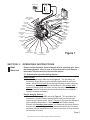
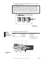
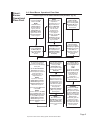
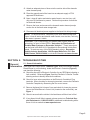
OWNER’S MANUAL
Model Number
AHE-100-03S - 12 VDC.
OWNER’S INFORMATION
Owner’s Name:
Address:
CUT HERE AND MAIL IN
City:
State:
Zip Code:
Telephone:
E-mail Address:
Motorhome Model:
Date of Purchase (Motorhome):
Aqua-Hot Model No. (reference Figure 1 “Marking Plate”):
Aqua-Hot Serial No. (reference Figure 1 “Marking Plate”):
Please Mail To:
Vehicle Systems’ Warranty Department
15549 East Highway 52
Ft. Lupton, CO 80621
Vehicle Systems, Inc.
Warranty Department
15549 East Highway 52
Ft. Lupton, CO 80621
Aqua-Hot™ Motor Coach Heating System Owner's Manual 09/03
TABLE OF CONTENTS
Section 1
Overview
1.0
Section 2
Operating Instructions
2.1
2.2
2.3
2.4
2.5
2.6
2.7
Section 3
Maintenance Schedule ..................................................... 11
Winterization
4.1
Section 5
Activating the Aqua-Hot Heating System ............................ 3
Zone Thermostat(s) Operation ........................................... 4
Using the Domestic Hot Water System .............................. 5
Using the Engine Preheat System ..................................... 5
Diesel-Burner Component Overview.................................. 7
Diesel-Burner Operational Flow-Chart ............................... 8
Precautions ...................................................................... 10
Maintenance
3.1
Section 4
Aqua-Hot Overview ............................................................. 1
Domestic Hot Water System ............................................ 13
Troubleshooting
5.1
5.2
General Information .......................................................... 15
Electronic Controller Diagnostic ....................................... 16
SECTION 1: OVERVIEW
Aqua-Hot
Overview
1.0 Activating the Aqua-Hot Heating System
The Aqua-Hot Heating System is an on-board Hydronic Heating System
(heating with hot water) that provides a continuous, on-demand supply of
domestic hot water, as well as interior zone heating where and when it is
needed. Both heating features are accomplished by a unique VDC-Powered
Diesel-Fired Burner and a VAC-Powered Electric Heating Element (120 VAC).
These two heating sources maintain the temperature of the Aqua-Hot's
solution of water and antifreeze. In addition, the Aqua-Hot has been designed
to preheat the vehicle's engine prior to starting. This preheat feature provides
an easy engine start-up whenever cool weather conditions are present. Be
sure to review Figure 1 for complete component overview.
NOTE: This Aqua-Hot product utilizes a Propylene Glycol (P.G.) based
water and antifreeze solution. This P.G. based solution is a Boiler type
antifreeze, which is Generally Recognized as Safe (“GRAS”) by the FDA.
For additional information regarding this GRAS antifreeze product, please
contact us at 1-800-685-4298 or visit our website at
www.vehiclesys.com.
Page 1
Aqua-Hot™ Motor Coach Heating System Owner's Manual 09/03
ELECTRONIC CONTROLLER
Hydro-Hot
R
Motor Coach Heating Specialists
Switch Panel
Low Tank-Level
Cutoff
Electric Heating
Element Status
Low Voltage
Heating Status
Reset
By Vehicle Systems
Engine Preheat
Pump
#5
#4
Pump #1
Heating Zones
Status
Diesel
Electric
Engine
Preheat
#3
Pump #2
#2
#1
Pump #3
Low Battery
Voltage Fault
Diesel-Burner
Status
Low Temp
Cutoff Status
Ho
Overload Fault
t
Electronic
Controller
Expansion
Tank
Co
ld
Heating Zones
Supply and Return
Ports
Fill / Radiator
Cap
Circulation
Pump #1
VAC Service
Input
Circulation
Pump #2
VAC Access
Panel
Circulation
Pump #3
Hour Meter
Engine Preheat
Circulation
Pump
Thermostat
Access Panel
Marking
Plates
Diesel-Burner
Head
Electric Heating
Element Access
Panel
Engine Coolant
Supply
Boiler Tank
Drain Valve
Diesel Fuel
Supply
Diesel-Burner
Control
Unit
Diesel Fuel
Return
Hot Water
Outlet
(Domestic Water)
Mixer
Valve
Cold Water
Inlet
(Domestic Water)
Engine
Coolant
Return
Pressure-Relief
Valve
Figure 1
SECTION 2: OPERATING INSTRUCTIONS
Heat
Sources
Please read the complete Owner’s Manual prior to operating your AquaHot Heating System. Also, be sure to fill out and mail in your Owner’s
Information Card located at the front of this manual.
2.1 Activating the Aqua-Hot Heating System
Diesel-Burner
Turn the Diesel switch ON, reference Figure 2. This procedure will
activate the Diesel-Burner and the indicator light located on the Diesel
switch. Allow 10-20 minutes for the Aqua-Hot System to reach operating
temperature. Please note that the Diesel-Burner is the primary heat
source for heating both the interior and the domestic hot water (such as
when cool ambient temperatures exist and/or when there is a high demand for domestic hot water).
Electric Heating Element
Turn the Electric switch ON, reference Figure 2. This procedure will
activate the 120 VAC Electric Heating Element and the indicator light
located on the Electric switch. Allow 1-2 hours for the Aqua-Hot System to
reach operating temperature. Please note that the Electric Heating
Element is a secondary heat source for heating both the interior and the
domestic hot water during low heating demand situations (such as when
moderate ambient temperatures exist and/or when there is a low demand
for domestic hot water).
Page 2
Aqua-Hot™ Motor Coach Heating System Owner's Manual 09/03
NOTE: Both the Diesel-Burner and the Electric Heating Element are
thermostatically controlled. Either, or both, heating sources will
automatically maintain the temperature of the Aqua-Hot's water and
antifreeze solution between approximately 160-190 (+/- 5) degrees
Fahrenheit. So to heat your motorhome / domestic hot water, simply
choose the desired heat source(s) and leave the switch(s) (i.e. Diesel
and/or Electric) ON.
Comfort
Control
2.2 Zone Thermostat(s) Operation
Interior Room Thermostats
Simply adjust each Interior Room Thermostat to the desired temperature.
Then whenever an Interior Room Thermostat “calls-for-heat”, the AquaHot’s Circulation Pump(s) and Interior Heat Exchanger Fans will be
activated. These devices together will supply warmth and comfort to each
interior heating zone. Please contact your specific motorhome
manufacturer for the exact location of the Interior Room Thermostat(s).
Fresh Water Tank Thermostat
Simply adjust the Thermostat (i.e. Bay Heating) to approximately 40
degrees Fahrenheit. This will prevent freezing of the domestic water
storage system. Please contact your specific motorhome manufacturer
for the exact location of the Fresh Water Tank Thermostat.
Hot Water
2.3 Using the Domestic Hot Water System
When the Aqua-Hot is at operating temperature, the domestic water is
automatically heated as it is being used. Because the Aqua-Hot does not
store any hot water, simply open any hot water faucet and a continuous
supply of domestic hot water will be present within a few seconds. This
hot water feature is continuous and is accomplished by the Aqua-Hot’s
Domestic Hot Water Heating System. Please note that the Diesel
switch must be ON to get an unlimited supply of hot water (i.e. during
showers).
Engine
Preheat
2.4 Using the Engine Preheat System
When the Aqua-Hot is at operating temperature, and the Diesel-Burner
and/or the 120 VAC Electric Heating Element switch(s) is ON, follow
these simple instructions:
A. Turn the Aqua-Hot's Engine Preheat switch ON, reference Figure 2.
This procedure will activate the Engine Preheat Circulation Pump and
circulate the engine's coolant through the Engine Preheat System.
This feature will adequately warm the engine for easy start-ups on
cool mornings.
NOTE: Allow approximately 1 to 2 hours of engine preheating run
time. Preheat duration will be shortest when the Diesel switch is ON.
Page 3
Aqua-Hot™ Motor Coach Heating System Owner's Manual 09/03
B. Turn OFF the Aqua-Hot's Engine Preheat switch whenever engine
preheating is not desired.
NOTE: The Aqua-Hot's Engine Preheating System acts as a supplemental heating source, in addition to the Diesel-Burner and the Electric
Heating Element. While traveling, the engine's heated coolant will automatically pass through the Engine Preheat / Motoraide System, transferring heat into the Aqua-Hot's Boiler Tank. This design feature reduces the
total operating hours of the Diesel-Burner and the Electric Heating Element.
By Vehicle Systems
Indicator
Light
Diesel
Electric
Engine
Preheat
Figure 2
DieselBurner
Component
Overview
2.5 Diesel-Burner Component Overview
1.
2.
3.
4.
5.
Control Unit
Motor
Ignition Coil
Clutch
Combustion Air Blower
6.
7.
8.
9.
10.
Fuel Solenoid
Electrode Holder
Ignition Electrodes
Fuel Nozzle
Heat Exchanger
11.
12.
13.
14.
15.
16.
Combustion Chamber
Exhaust Port
Flame Sensor
Fuel Pump
Fuel Ports (Supply / Return)
Combustion Air Intake Port,
with Adjustable Shutter
Figure 3
Aqua-Hot™ Motor Coach Heating System Owner's Manual 09/03
Page 4
DieselBurner
Operational
Flow-Chart
2.6 Diesel-Burner Operational Flow-Chart
~ Reference Figure 3 for all numbers indicated inside parenthesis. (e.g. #8).
Operation sequence once
the Aqua-Hot’s Diesel
switch is turned ON.
NOTE:
The Diesel switch’s
Indicator Light will
illuminate (reference
Figure 2), while the
Heating Status and
Diesel-Burner Status
lights illuminate on the
Electronic Controller,
reference Figure 5.
The Motor (#2), which
turns the Combustion
Air Blower (#5) and
drives the Fuel Pump
(#14), will begin to
operate.
The combustion process will
continue to operate in this
manner until one of the following
take’s place:
A.) The VDC / VAC Control
Thermostat, which senses
coolant temperature, reaches the
preset temperature of
approximately 190 (+/- 5)
degrees fahrenheit.
NOTE:
If process "A" occurs, the
Heating Status and DieselBurner Status lights on the
Electronic Controller will go
OFF, reference Figure 5.
B.) The Aqua-Hot’s Diesel switch
is turned OFF.
NOTE:
If process "B" occurs, the Diesel
switch’s Indicator Light, on the
Switch Panel (reference Figure
2), will go OFF along with the
Heating Status and DieselBurner Status lights on the
Electronic Controller, reference
Figure 5.
NOTE:
If the Aqua-Hot’s coolant
temperature is
approximately 190 (+/- 5)
degrees fahrenheit, or
higher, the Motor (#2)
will not operate. Only
when the coolant
temperature has
dropped below 160
(+/- 5) degrees
fahrenheit, and the VDC
/ VAC Control
Thermostat is calling for
heat, will the Motor (#2)
begin to operate.
After approximately 10 - 25
seconds, the Fuel
Solenoid (#6) opens and
fuel is sprayed into the
Combustion Chamber
(#11) through the Fuel
Nozzle (#9).
Once the heater switches
OFF, thermostatically or
manually, the Fuel
Solenoid (#6) closes,
which interrupts the supply
of diesel fuel to the Fuel
Nozzle (#9).
The Motor (#2) will
continue to run for
approximately three (3)
additional minutes. This
process is refered to as
the purge-cycle, which
cools down the heater’s
internal components
and purges the
Combustion Chamber
(#11) of any residual
exhaust gases.
NOTE:
When the Aqua-Hot’s
Diesel-Burner is switched
OFF, by the VDC / VAC
Control Thermostat, the
following process will take
place:
Simultaneously the
Ignition Coil (#3)
produces a high voltage
spark across the Ignition
Electrodes (#8), which
ignites the incoming
air-fuel mixture.
Once the ignited air-fuel
mixture (FLAME) is
observed by the Flame
Sensor (#13), the Ignition
Coil (#3) will automatically
switch OFF. The
combustion process now
continues to operate
unassisted.
1.) The Motor (#2) will
shut-off once the three (3)
minute purge-cycle has
expired.
-THEN2.) The Aqua-Hot’s DieselBurner will automatically
turn back ON once the
coolant temperature
reaches the preset
temperature of
approximately 160 (+/- 5)
degrees fahrenheit.
SUMMARY:
The Aqua-Hot’s DieselBurner is in stand-by
mode anytime the operator
activates the Diesel switch
(reference Figure 2) to the
ON position. The DieselBurner will then
automatically ignite and
maintain the coolant
temperature in the AquaHot’s Boiler Tank without
additional involvement
from the operator.
Page 5
Aqua-Hot™ Motor Coach Heating System Owner's Manual 09/03
Important
Information
2.7 Precautions
WARNINGS:
• The Aqua-Hot's Exhaust is HOT!
• DO NOT park in areas where dry conditions exist underneath the
vehicle, as a fire may result (i.e. in a dry grassy field for example).
• DO NOT operate the Aqua-Hot’s Diesel-Fired Burner inside an
enclosed building.
• The Heater should be switched OFF when refueling.
CAUTION: DO NOT operate the Diesel-Burner and/or the Electric
Heating Element without the water and antifreeze solution in the AquaHot’s Boiler Tank. Failure to do so will cause serious damage to the
Heater.
SECTION 3: MAINTENANCE
Upkeep
3.1 Maintenance Schedule
Monthly
Check the Aqua-Hot's solution of water and antifreeze to ensure that it is at the
proper level. Do this by visually checking the coolant level in the Aqua-Hot's
Expansion Tank, reference Figure 1. Please note that the coolant level should
be checked only when the Aqua-Hot is at maximum operating temperature
(i.e. when the Diesel-Burner cycles OFF), “HOT.”
WARNING: When the Aqua-Hot is at maximum operating temperature (HOT),
DO NOT loosen the Radiator Cap. If removed, scalding by hot vapor or coolant
could result.
NOTE: This Aqua-Hot product utilizes a Propylene Glycol (P.G.) based water
and antifreeze solution. This P.G. based solution is a Boiler type antifreeze,
which is Generally Recognized as Safe (“GRAS”) by the FDA. For additional
information regarding this GRAS antifreeze product, please contact us at 1-800685-4298 or visit our website at www.vehiclesys.com.
If the coolant needs replenishing, fill the Aqua-Hot’s Expansion Tank to the FULL
HOT level mark. Be sure to use a 50/50 mixture of water and (P.G.) antifreeze.
Annually
WARNING: Before cleaning or servicing, disconnect all power supplies.
To keep your Aqua-Hot running smoothly, it is ideal to have the Diesel-Burner
tuned-up annually. A tune-up should consist of a new Fuel Nozzle and Fuel
Page 6
Aqua-Hot™ Motor Coach Heating System Owner's Manual 09/03
Filter, along with a thorough cleaning of the Combustion Chamber, if
necessary (reference Figure 4). To ensure maximum Diesel-Burner
performance, always use the recommended Fuel Nozzle (i.e. 0.35
GPH) and Fuel Filter (i.e. 10 Micron) when replacing these parts.
Reference the Aqua-Hot “Parts Manual” for spare parts information. If
detailed replacement instructions are needed, please reference the
Aqua-Hot “Shop Manual” for your specific model of Aqua-Hot, or contact
our Technical Department at 1-800-685-4298 for the nearest Aqua-Hot
Service Center.
CAUTION: DO NOT operate the Diesel-Burner and/or the Electric
Heating Element without the water and antifreeze solution in the AquaHot’s Boiler Tank. Failure to do so will cause serious damage to the
Heater.
Combustion
Chamber
Fuel Filter
(10 Micron)
Fuel Nozzle
(0.35 GPH)
Figure 4
SECTION 4: WINTERIZATION
Storage
4.1 Domestic Hot Water System
The Aqua-Hot's Domestic Hot Water Heating System must be completely
drained of domestic water any time the heater is stored where freezing
temperatures may be experienced.
CAUTION: Not winterizing your Aqua-Hot, when freezing temperatures
are present, will result in serious damage to the Aqua-Hot's Domestic
Hot Water Heating System.
NOTE: The Aqua-Hot can still be used for interior zone heating even if the
domestic hot water system has been drained and winterized.
Please follow the instructions listed below when winterizing the Aqua-Hot’s
Domestic Hot Water Heating System:
A. Completely drain the fresh water storage tank.
NOTE: If your motorhome is equipped with appliances that use fresh
water (i.e. ice makers, water purifiers, etc.) follow the manufacturer's
recommendation for winterization.
B. Disconnect the domestic water demand pump's suction line from the
fresh water storage tank.
Page 7
Aqua-Hot™ Motor Coach Heating System Owner's Manual 09/03
C. Attach an adequate piece of hose onto the suction side of the domestic
water demand pump.
D. Place the opposite end of the hose into an adequate supply of FDA
approved RV-Antifreeze.
E. Open / close all interior and exterior water faucets, one at a time, until
only pure RV-Antifreeze is present. Perform this procedure for both the
hot and cold faucets.
F. Remove the hose and reconnect the domestic water demand pump's
suction line to the fresh water storage tank.
G. Disconnect all electrical power supplies to the Aqua-Hot during storage.
NOTE: For de-winterization, completely fill the fresh water storage tank.
Open / close all interior and exterior water faucets, one at a time, until only
clear water is present / visible.
CAUTION: If you’re disinfecting your potable water system, after dewinterizing, be sure to follow RVIA’s “Instruction for Disinfection of
Potable Water Systems on Recreation Vehicles.” These instructions
can be found in the ANSI A119.2 Handbook for Recreational Vehicle Standards. To receive a copy of this RVIA Standard, write to: Recreation
Vehicle Industry Association, 1896 Preston White Drive, P.O. Box
2999, Reston, VA 20195-0999, or visit the RVIA website at www.rvia.com.
SECTION 5: TROUBLESHOOTING
General
Information
5.1 General Information
If the Aqua-Hot’s Diesel switch “Indicator Light” does not illuminate, and the
Diesel-Burner is not functioning, locate the Electronic Controller (Figure 5)
and check the following:
A. Check the Aqua-Hot’s Electronic Controller for any RED lights indicating a
fault condition. Reference Figure 5 and the Electronic Controller Troubleshooting section to identify these fault conditions.
B. Check for loose wire connections on the Electronic Controller’s Plug
terminals. When checking for loose plug terminals, remove the Electronic
Controller Faceplate by unscrewing the four cover screws.
C. Remove the Aqua-Hot’s Access Cover and check for loose plug connectors on the Diesel-Burner's Control Unit (located on the under side), see
Figure 1.
D. Check to ensure that the vehicle’s fuel tank has a sufficient level of fuel.
E. If your Aqua-Hot still fails to operate, please contact our Technical Support Department at 1-800-685-4298 for additional troubleshooting assistance or visit our website at www.aqua-hot.com.
Page 8
Aqua-Hot™ Motor Coach Heating System Owner's Manual 09/03
Electronic
Controller
5.2 Electronic Controller Diagnostic
ELECTRONIC CONTROLLER
ydro-Ho
Hott
H ydro-
R
Low Tank-Level
Cutoff
Electric Heating
Element Status
Low Voltage
Heating Status
Reset
Engine Preheat
Pump
#5
#4
Pump #1
Heating Zones
Status
#3
Pump #2
#2
#1
Pump #3
Low Battery
Voltage Fault
Diesel-Burner
Status
Low Temp
Cutoff Status
Overload Fault
Figure 5
Low Tank-Level Cutoff Indicator Light:
This indicator light will illuminate RED when either the 120 VAC Electric Heating Element and/or Diesel-Burner have automatically shutdown due to a low
water and antifreeze solution level inside the Aqua-Hot’s Boiler Tank. This fault
will automatically reset when the low level condition is corrected.
Low Battery Voltage Fault Indicator Light:
This indicator light will illuminate RED whenever the VDC voltage level is too
low for the Aqua-Hot to operate properly. This fault must be manually reset
after the voltage level has been restored to the VDC battery system, see Low
Voltage Reset below.
Low Voltage Reset (Button):
The Aqua-Hot’s Electronic Controller must be manually reset whenever the
Low Battery Voltage Fault indicator light has been activated. To reset the
Electronic Controller, simply depress the “Low Voltage Reset” button located
on the Electronic Controller (use a thin straight object to access the reset
button through the small hole in the Faceplate).
Overload Fault Indicator Light:
This indicator light will illuminate RED whenever one of the following conditions
have occurred:
1. The Aqua-Hot is off due to an electrical overload (i.e. short) in the main
VDC power supply circuitry.
2. The Aqua-Hot is off due to a combination of high electrical VDC power
loads and a high surface temperature of the Electronic Controller.
Page 9
Aqua-Hot™ Motor Coach Heating System Owner's Manual 09/03
Electronic
Controller,
continued
The Aqua-Hot will automatically restart once the electrical overload (i.e. short)
and/or high heat condition is corrected.
Heating Zones Status Indicator Lights:
These five indicator lights (separately) will illuminate GREEN whenever a
Zone Thermostat, for each particular zone, is calling for heat. The GREEN
indicator lights also indicate that VDC power is being supplied to the particular
interior heating zone’s Heat Exchangers (i.e. fan motors). If any of the five
indicator lights illuminate RED, it indicates that an electrical overload condition
(i.e. short) has occurred in a particular heating zone’s circuitry.
NOTE: A short in either a heating zone’s Interior Room Thermostat or
heating zone’s Heat Exchanger circuit, will cause the indicator light to
illuminate RED.
Pumps #1, #2, and #3 Indicator Lights:
These indicator lights (separately) will illuminate GREEN whenever a
Circulation Pump is operating. If any of the three indicator lights illuminate
RED, it indicates that an electrical overload condition (i.e. short) has occurred
in the particular component’s circuitry.
NOTE: The Zone Circulation Pumps (separately) are activated whenever
a Zone Thermostat calls for heat.
Engine Preheat Pump Indicator Light:
This indicator light will illuminate GREEN whenever the Engine Preheat Pump
is operating. Please note that this light will only be active if the Engine Preheat
switch is ON in conjunction with either the Diesel and/or the Electric switch. If
this indicator light illuminates RED, it indicates an electrical overload condition
(i.e. short) has occurred in this particular component’s circuitry.
Heating Status Indicator Light:
This indicator light will illuminate GREEN whenever the Aqua-Hot’s VDC / VAC
Control Thermostat is calling for heat, allowing the water and antifreeze
solution in the Aqua-Hot’s Boiler Tank to be heated by either the Diesel-Burner
and/or the 120 VAC Electric Heating Element. When this indicator light is off,
no heat is being supplied to the Aqua-Hot’s Boiler Tank.
NOTE: The Aqua-Hot’s VDC / VAC Control Thermostat will automatically
activate the Diesel-Burner and/or the 120 VAC Electric Heating Element,
only if the Diesel and/or Electric switch is in the ON position. So to heat
your motorhome / domestic hot water, simply choose the desired heat
source(s) and leave the switch(s) (i.e. Diesel and/or Electric) ON.
Electric Heating Element Status Indicator Light:
This indicator light will illuminate GREEN whenever the Aqua-Hot’s 120 VAC
Electric Heating Element is operating and providing heat to the Aqua-Hot’s
Boiler Tank. Please note that this light will only be active if the Electric switch
is in the ON position. If this indicator light illuminates RED, it indicates an
electrical overload condition (i.e. short) has occurred in the Electric Heating
Element’s VDC powered circuitry.
Page 10
Aqua-Hot™ Motor Coach Heating System Owner's Manual 09/03
WARRANTY INFORMATION
- FOR AQUA-HOT MODELS Vehicle Systems Inc. warrants the AQUA-HOT Heater to be free from defects in material and workmanship under normal use and service for a period of two (2) years on both parts and labor commencing upon the original date of registration of the vehicle. The Warranty period may not however,
exceed 36 months from the original date of delivery by Vehicle Systems, Inc. Replacement parts are
warranted for the remainder of the Heater's standard warranty period or for six months (180 days),
whichever is greater.
This warranty is conditional upon proper use of the Heater by the end-user. This warranty
does not apply to damage or failure of the AQUA-HOT Heater, or the vehicle into which it
was installed, due to improper installation, assembly, maintenance, abuse, neglect, accident, or the use of parts not supplied by Vehicle Systems Inc. Vehicle Systems is not responsible for incidental or consequential damages.
The intent of this warranty is to protect the end-user of the heating system from such defects, which
would occur in the manufacture of the product. The warranty is not intended to protect the end-user
from problems, which are outside the ability of Vehicle Systems’ control.
To obtain warranty repair authorization or for additional product information, please contact our
Technical Support Department at 1-800-685-4298 (8 AM to 5 PM Mountain Standard Time).
OWNER’S SERVICE LOG:
Date
Service Performed
Service Center
Page 11
Aqua-Hot™ Motor Coach Heating System Owner's Manual 09/03
(Continued)
Date
OWNER’S SERVICE LOG:
Service Performed
Service Center
Page 12
Aqua-Hot™ Motor Coach Heating System Owner's Manual 09/03
Motor Coach Heating Specialists • Manufacturers and Distributors
15549 East Highway 52 • Fort Lupton, Colorado 80621 • 1-800-685-4298 • Fax: 303-857-9000
© Copyright 2002 Vehicle Systems, Inc. All rights reserved
www.vehiclesys.com
LTE-LMA-301
* Asterick denotes 24 volt model
Aqua-Hot Motor Coach Heating System Parts Manual 06/02
Page