1
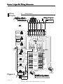
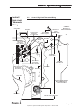
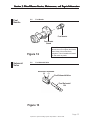
Shop Manual Model Numbers AHE-100-02S - 12 VDC AHE-200-02S - 24 VDC Aqua-Hot™ Hydronic Heating System Shop Manual REV-A 03/02 TABLE OF C ONTENT S CONTENT ONTENTS Sections 1 2 3 4 Aqua-Hot Information 1.1 Aqua-Hot Component Overview 1.2 Aqua-Hot Identification Plate Aqua-Hot Wiring Information 2.1 Wiring Diagram 2.2 Control / High-Limit Thermostat Wiring Diesel-Burner Information 3.1 Diesel-Burner Component Overview 3.2 Operational Flow-Chart 3.3 Diesel-Burner Identification Plate Diesel-Burner Wiring Information 4.1 5 6 Control Unit Wiring Diesel-Burner Service, Maintenance, and Repair Information 5.1 General Maintenance 5.2 Detaching the Diesel-Burner Head 5.3 Flame Detection Photocell 5.4 Ignition Electrodes 5.5 Fuel Nozzle 5.6 Fuel Solenoid Valve 5.7 Fuel Pump Troubleshooting 6.1 Troubleshooting Flow-Chart 7 Aqua-Hot Warranty Information 8 Parts List 9 Special Tools Aqua-Hot™ Hydronic Heating System Shop Manual REV-A 03/02 Section 1: Aqua-Hot Information Overview 1.1 Aqua-Hot Component Overview Ho t Expansion Tank Zone # A Supply Co ld Zone # A Return Zone # B Return Zone # B Supply Fill / Radiator Cap Thermostat Access Panel Zone # C Return VAC Service Input Zone # C Supply VAC Access Panel Zone Circulation Pump Fuse Block Engine Preheat Circulation Pump I.D Plates Zone Relay #A Diesel-Burner Head Zone Relay #B Engine Coolant Supply Zone Relay #C Electric Heating Element Access Panel Diesel Fuel Supply Diesel Fuel Return Engine Coolant Return Diesel-Burner Control Unit Mixer Valve Pressure-Relief Cold Water Valve Inlet Hot Water (Domestic Water) Outlet (Domestic Water) Figure 1 Page 1 Aqua-Hot™ Hydronic Heating System Shop Manual REV-A 03/02 Section 1: Aqua-Hot Information Aqua-Hot I.D. Plate 1.2 Aqua-Hot Identification Plate MODEL No. AHE-100-02S SERIAL No. 02-637 Install in strict compliance with local codes, NFPA 501c and manufacturer's instructions. For installation only in compartment completely closed off from living quarters and accessible only from the outdoors. Exhaust pipe must not terminate beneath the vehicle. Caution! Do not adjust the Heater's Tempering Valve. Tampering with the Tempering Valve can increase the risk of scald injury. Use copper electrical conductors only. Approved for use in recreational vehicles and in marine applications. Complies with the requirements of UL 307A and (USCG) CFR33. The I.D. Plate is located on the right sidewall of heating unit, directly below the VAC Access Panel, see Figure 1. Serial Number Box Model Number Box 12 VDC/110 VAC 1650 W Fuel: Diesel 1 or 2 Firing rate: 50,000 btu/hr patent No. 5,025,985 and 5,067,652 Listing No. PO BOX 7025 SALT LAKE CITY, UTAH 84157 15717 MODEL No. AHE-100-02S SERIAL No. 02-637 The lower portion of the I.D. Plate is located inside the heating unit to the right of the Electric Heating Element Access Panel, see Figure 1. Serial Number Box Model Number Box Figure 2 Page 2 Aqua-Hot™ Hydronic Heating System Shop Manual REV-A 03/02 Section 2: A qua-H ot Wiring IInfor nfor mation Aqua-H qua-Hot nformation Wiring Diagram 2.1 Wiring Diagram Brown Key Indicator Light ) Indicates Field Wiring (-) (+) ( Control Switch Living Room Thermostat ( - ) Wiring Diagram (-) TSTAT (+) TSTAT Bathroom Thermostat ( - ) Chassis Ground (B) (A) TSTAT Bedroom Thermostat ( - ) Engine Preheat Switch ( - ) Zones (C) Green Living Room Pump A-Zone Red Green Blue White Brown Bathroom Pump Fresh Water Tank / Bay Pump B-Zone Blue Red Green Power Post (+) Battery Connection Blue 10A 15A B-1 B-4 Bathroom (B-Zone ) Cozy Heat Exchanger (+) Bedroom (C-Zone ) Cozy Heat Exchanger + + + 6 + 4 + + + 6 + 4 + + + 6 + + A-Zone Relay + + + + + B-Zone Relay C-Zone Relay + + + + + + + + + + B-6 (+) 4 Red B-3 10A Fans Brown Figure 3 B-2 Diesel-Burner C-Plug (8 Pin) (+) (-) B-1 Living Room (A-Zone ) Cozy Heat Exchanger (-) Pumps F Red Black Black White (+) (-) + E Yellow Engine Pump (-) + D B-4 Ground Post (-) Battery Connection C OPEN C-Zone B 10A A 10A Bedroom Pump Fresh Water Tank / Bay Whisper Heat Exchanger Diesel-Burner B-Plug (6 Pin) C-2 Orange Blue TSTAT Black Fresh Water Tank / Bay Thermostat (B-Zone ) For Technical Support call 1-800-685-4298 Page 3 Aqua-Hot™ Hydronic Heating System Shop Manual REV-A 03/02 Section 2: A qua-H ot Wiring IInfor nfor mation Aqua-H qua-Hot nformation Control / High-Limit Thermostat Wiring 2.2 Control / High-Limit Thermostat Wiring Orange Wire Blue Wire VAC High-Limit Thermostat, 230˚ F White Dot 12-2 ROMEX Cable w/ground Green Wire (Ground) VAC Service Input / ROMEX Clamp "COMMON" White Wire to White ROMEX Wire Black Wire VDC Control Thermostat, 190˚F, Blue Dot Thermostat Thermostat Thermostat Thermostat Thermostat Thermostat Thermostat Thermostat Thermostat RED 110 Element Ground Post Thermostat Thermostat Thermostat Black Wire VDC High-Limit Thermostat, 230˚F, Black Aqua-Hot Junction Box VAC Control Thermostat, 198˚F, Red Dot "GROUND" Green Wire to ROMEX Copper Wire White Wire Black Wire Purple Wire "120 VAC POWER SUPPLY" Black ROMEX Wire to "LOAD" Black Wire White Wire 120 VAC / 1650 Watt Electric Heating Element Figure 4 Page 4 Aqua-Hot™ Hydronic Heating System Shop Manual REV-A 03/02 Section 3: Diesel-Burner Information Overview 1. 2. 3. 4. 5. 6. 7. 8. 9. Control Unit Motor Ignition Coil Clutch Combustion Air Fan Fuel Solenoid Valve Electrode Holder Ignition Electrodes Fuel Nozzle 3.1 Diesel-Burner Component Overview 10. 11. 12. 13. 14. 15. 16. Combustion Chamber Heat Exchanger Exhaust Port Flame Detection Photocell Fuel Pump Fuel Ports (Supply / Return) Combustion Air Port (Intake) with Adjustable Shutter Figure 5 Page 5 Aqua-Hot™ Hydronic Heating System Shop Manual REV-A 03/02 Section 3: Diesel-Burner Information DieselBurner Operational Flow-Chart Operation sequence once the Aqua-Hot's Diesel-Burner Control Switch is turned ON. 3.2 Operational Flow-Chart ~ Reference Figure 5 for all numbers indicated inside parenthesis. (i.e #8). Simultaneously the "IGNITION COIL" (#3) produces a High Voltage Spark across the "IGNITION ELECTRODES" (#8) which ignites the incoming Air / Fuel The Control Switch's indicator light will illuminate. The "MOTOR" (#2) (which turns the "COMBUSTION AIR FAN" (#5) and drives the "FUEL PUMP" (#14)) will begin to run. NOTE: Once the ignited Air / Fuel mixture (FLAME) is observed by the "FLAME DETECTION PHOTOCELL" (#13), the "IGNITION COIL" (#3) will automatically switch OFF. The combustion process now continues to operate unassisted. NOTE: If the Aqua-Hot's Coolant reservoir temperature is approximately 175 degrees Fahrenheit, or higher, the "MOTOR" (#2) will not operate. Only when the temperature has dropped below 175 degrees Fahrenheit will the "VDC CONTROL THERMOSTAT" (see Figure 4) allow the "MOTOR" (#2) to operate. The "MOTOR" (#2) will continue to run for approximately three (3) additional minutes. This is called the "Purge-Cycle", which cools down the Heater's internal components and purges the "COMBUSTION CHAMBER" (#10) of any residual exhaust gases. The combustion process will continue to operate in this manner until: When the Aqua-Hot DieselBurner is switched OFF by the "VDC CONTROL THERMOSTAT" (see Figure 4): A.) The "MOTOR" (#2) will shut-off once the three (3) minute "Purge-Cycle" has expired. B.) The Aqua-Hot's DieselBurner will automatically turn back ON once the coolant temp. reaches the preset temperature of approximately 175 degrees Fahrenheit. A.) The "VDC CONTROL THERMOSTAT", (see Figure 4) (which senses Coolant Temp.), reaches the preset temperature of approximately 190 degrees Fahrenheit. B.) The Aqua-Hot's DieselBurner Control Switch is turned OFF. After approximately 10 - 25 seconds the "FUEL SOLENOID VALVE" (#6) opens and fuel is sprayed into the "COMBUSTION CHAMBER" (#10) through the "FUEL NOZZLE" (#9). Once the Heater switches OFF, thermostatically or manually, the "FUEL SOLENOID VALVE" (#6) closes, which interrupts the supply of diesel fuel to the "FUEL NOZZLE" (#9). SUMMARY: The Aqua-Hot's Diesel-Burner is operational anytime the operator activates the Diesel-Burner Control Switch to the ON position. The Diesel-Burner will then automatically maintain the temperature of the coolant without any additional involvement from the operator. Page 6 Aqua-Hot™ Hydronic Heating System Shop Manual REV-A 03/02 Section 3: Diesel-Burner Information Diesel Burner I.D. Plate 3.3 Diesel-Burner Identification Plate Fabrikschild-Duplikat gultig nur zusammen mit Original Thermosysteme GmbH MADE IN GERMANY DBW 2010.75 HEIZGERAT Typ Spannung / El. Leistung 12 V / 60W 13,2 kW Warmestrom Brennstoff Diesel zul. Betriebsuberdruck 2 bar Prufzeichen Fabriknummer 1B230410 Inbetriebnahmejahr 2001 2002 2003 Model Type Voltage / Wattage Fuel Type Serial Number (230410) Diesel-Burner I.D. Plate is located on the left side of the Diesel-Burner Head Diesel-Burner Head Figure 6 Page 7 Aqua-Hot™ Hydronic Heating System Shop Manual REV-A 03/02 Section 4: D iesel-B ur ner Wiring IInfor nfor mation Diesel-B iesel-Bur urner nformation Control Unit Wiring 4.1 Control Unit Wiring ( + ) VDC Control Thermostat (Orange) ( + ) Blower Motor (Black) ( - ) To Overheat Circuit And Solenoid Valve (Blue) ( + ) Indicator Light (Blue) ( - ) Battery (Brown) ( + ) On / Off Switch With Low Voltage Protection (White) B-Plug 1 4 2 5 3 6 1 5 2 6 7 4 8 C-Plug ( + ) To Ignition Coil (Yellow) ( + ) Battery (Red) ( - ) Indicator Light (Green) ( + ) From Normally Closed VDC Control Thermostat (White) ( + ) Flame Detector (Green) ( - ) For All Heater Components (Brown) Figure 7 Page 8 Aqua-Hot™ Hydronic Heating System Shop Manual REV-A 03/02 Section 5: Diesel-Burner Service, Maintenance, and Repair Information Upkeep 5.1 General Maintenance Monthly Check the Aqua-Hot's solution of water and antifreeze to ensure that it is at the proper level. Do this by visually checking the coolant level in the Aqua-Hot's Expansion Tank, see Figure 1. This should be checked only when the Aqua-Hot is at full operating temperature, “HOT.” Annually CAUTION: Before cleaning or servicing, disconnect all power supplies. It is ideal to have your Aqua-Hot tuned-up yearly. A tune-up should consist of a Fuel Nozzle and Fuel Filter replacement and a thorough cleaning of the Combustion Chamber, if necessary, see Figure 8. This simple tune-up will keep your Aqua-Hot running smoothly throughout the year. This annual tune-up will also allow service personnel to inspect for wear and tear of other components. CAUTION: Operating the Aqua-Hot’s Diesel-Burner or the 120 VAC Electric Heating Element without the water and antifreeze solution will cause serious damage to the Heater. Fuel Nozzle Fuel Filter Combustion Chamber Figure 8 Page 9 Aqua-Hot™ Hydronic Heating System Shop Manual REV-A 03/02 Section 5: D iesel-B ur ner SSer er vice, M aintenance, and R epair IInfor nfor mation Diesel-B iesel-Bur urner ervice, Maintenance, Repair nformation Detaching Diesel-Burner Head 5.2 Detaching the Diesel-Burner Head Grommets Eye-Bolts and Nuts Blower Casing Figure 9 Diesel Fuel Supply Diesel Fuel Return Instructions For Detaching the Diesel-Burner Head from the Aqua-Hot CAUTION: Before detaching the Diesel-Burner Head, disconnect all power supplies. 1. Loosen the two Eye-Bolt Nuts and swing the Eye-Bolts out of the way. 2. With both hands, carefully pull the Diesel-Burner away from the AquaHot, approximately 4-5 inches. Please note that you may have to lift the head slightly while pulling it away from the Aqua-Hot. 3. Rotate the head approximately 90 angular degrees to the right or until all the internal components are visible. NOTE: It may be necessary to disconnect the two RED wires, which are connected to pin #6 of the B-Zone relay, when rotating the head beyond 90 degrees, see Figure 3. CAUTION: When reattaching the Diesel-Burner Head to the Aqua-Hot, be sure to properly align the head and DO NOT over tighten the Eye-Bolt Nuts. An improper alignment and or an over tightening of the Eye-Bolt Nuts can cause damage to the Diesel-Burner Head's aluminum-cast housing (Blower Casing), see Figure 9. Page 10 Aqua-Hot™ Hydronic Heating System Shop Manual REV-A 03/02 Section 5: D iesel-B ur ner SSer er vice, M aintenance, and R epair IInfor nfor mation Diesel-B iesel-Bur urner ervice, Maintenance, Repair nformation Flame Detection Photocell 5.3 Flame Detection Photocell Flame Detection Photocell Photo Disc Green Wire Flame Detection Photocell Cleaning Notes Figure 10 Ignition Electrodes 5.4 For light dirt, dust and carbon deposits simply wipe off the Flame Detection Photocell with a soft cloth. Should heavy carbon deposits be present, completely remove the Flame Detection Photocell from the Photo Disc and clean with carburetor cleaner. Blue Wire Ignition Electrodes Note: Electrode Adjustment Gauge is located on the outside surface of the DieselBurner on the lefthand side. Electrode Adjustment Gauge Note: Once adjustment is complete, remove Electrode Adjustment Gauge and reattach to Diesel-Burner. Ignition Electrodes Figure 11 Adjustment gauge properly positioned Page 11 Aqua-Hot™ Hydronic Heating System Shop Manual REV-A 03/02 Section 5: D iesel-B ur ner SSer er vice, M aintenance, and R epair IInfor nfor mation Diesel-B iesel-Bur urner ervice, Maintenance, Repair nformation Fuel Nozzle 5.5 Fuel Nozzle Fuel Nozzle Fuel Nozzle Stand Figure 12 Solenoid Valve 5.6 Note: When replacing the Fuel Nozzle, be sure to tighten the Nozzle, then loosen 1/4 turn and firmly retighten. This will establish a seated fit and avoid any leaks. Fuel Solenoid Valve Electrical Terminals (+) (-) Fuel Solenoid Valve Fuel Solenoid Kit Figure 13 Page 12 Aqua-Hot™ Hydronic Heating System Shop Manual REV-A 03/02 Section 5: D iesel-B ur ner SSer er vice, M aintenance, and R epair IInfor nfor mation Diesel-B iesel-Bur urner ervice, Maintenance, Repair nformation Fuel Pump 5.7 Fuel Pump Fuel Pump Pressure Regulation (Adjustment) Note: Adjust fuel pressure to 145 PSI. (+) Clockwise rotation increases fuel pressure. (-) Counter Clockwise rotation decreases fuel pressure. Fuel Pressure Gauge Note: Fuel Pressure gauge replaces the Fuel Nozzle when adjusting fuel pressure. Figure 14 Page 13 Aqua-Hot™ Hydronic Heating System Shop Manual REV-A 03/02 Section 6: Troubleshooting Troubleshooting Flow-Chart 6.1 1. Check indicator light bulb. Replace if necessary. Troubleshooting Flow-Chart 2. Remove the Aqua-Hot's ACCESS COVER. Is the indicator light illuminated? Turn the Control Switch ON. No 3. Check Aqua-Hot fuses (E & F) for continuity, see Figure 3. Replace if necessary. 4. Check DC power supply at the "POWER POST" and "GROUND POST", see Figure 3. Yes 5. Attempt heater restart. 1. Remove the AquaHot's ACCESS COVER. No 2. Check Aqua-Hot fuse (F) for continuity, see Figure 3. Replace if necessary. Is the DieselBurner's "MOTOR" (#2) operating? 1. Remove the Aqua-Hot's ACCESS COVER. Yes 2. Remove the "THERMOSTAT ACCESS PANEL", see Figure 1. 3. Check the Diesel-Burner's "VDC HIGH-LIMIT THERMOSTAT" for continuity, see Figure 4. NOTE: The indicator light will illuminate for only 30 seconds if fuse (F) is blown (open circuit). NOTE: This Thermostat protects against overheating temperatures. 3. Attempt heater restart. Check the DieselBurner's "VDC CONTROL THERMOSTAT" (blue dot) for continuity, see Figure 4. 1. Replace Thermostat. NOTE: Aqua-Hot operating temperature must be below 170 degrees Fahrenheit when checking the "VDC CONTROL THERMOSTAT" for continuity, see Figure 4. 2. Attempt heater restart Is there continuity across the Thermostat? Yes No No Is there continuity across the Thermostat? 1. Replace the Thermostat. 2. Attempt heater restart. Yes Page 14 Aqua-Hot™ Hydronic Heating System Shop Manual REV-A 03/02 Section 6: Troubleshooting 1. Check for fuel leaks in the Diesel-Burner's "DIESEL FUEL SUPPLY" line, see Figure 9. Repair if necessary. 1. Turn the Control Switch OFF. 2. Remove the fuel-line from the Aqua-Hot's "DIESEL FUEL RETURN" (see Figure 1) and place a short piece of fuel line in its place. Is the fuel flow consistent without air bubbles? No 3. Put the opposite end of the fuel line in a container. 3. Reattach "DIESEL FUEL RETURN" line, see Figure 1. 4. Place the probes of a DCmulti meter into plug locations, B-1 (+) and B-2 (-), of the DieselBurner's "CONTROL UNIT" (#1), see Figures 1 and 7. Also, measure the voltage across B-2 (-) and B-4 (+). 4. Attempt heater restart. Yes 1. Check the Control Switch's: 5. Turn the Control Switch ON. A. wire connections. B. fuse (E) for continuity, see Figure 3. 6. Observe the fuel flow. Flow should be consistent without air bubbles. 1. Check the voltage level of the DC-multi meter. NOTE: Voltage level should be within 0.5 volts of the system's DC battery voltage. Does the DCmulti meter indicate acceptable system voltage? No 2. Completely cover the "FLAME DETECTION PHOTOCELL" (#13) (see Figure 10) with a shop rag. 3. Turn the Control Switch ON. After approx. 20 seconds of operation a bright blue arc (spark) should appear across the "IGNITION ELECTRODES" (#8), see Figure 11. 2. Check DC power supply wires and connections, see Figure 3. 3. Reattach "DIESEL FUEL RETURN" line, see Figure 1. Yes 1. Inspect the "FLAME DETECTION PHOTOCELL" (#13) (see Figure 10) for dust and or sooty carbon deposits. Clean if necessary. 2. Check the Aqua-Hot's "FUEL FILTER" (see Figure 8) for clogging. Replace if necessary. 4. Attempt heater restart. 1. Turn the Control Switch OFF. 2. Reattach "DIESEL FUEL RETURN" line, see Figure 1. 3. Detach the "DIESEL-BURNER HEAD" from the Aqua-Hot, see Figures 1 and 9. 4. Disconnect one of the wires from the "FUEL SOLENOID VALVE" (#6), see Figure 13. NOTE: Do not remove or cut any of the external wires attached to the "DIESEL-BURNER HEAD". ! WARNINGS: 1. DO NOT attempt to restart the Aqua-Hot when the "DIESELBURNER HEAD" is detached. An open flame can result and cause serious personal injury. 2. To prevent a fire hazard, be sure to disconnect one of the "FUEL SOLENOID VALVE" (#6) (see Figure 13) wires. Page 15 Aqua-Hot™ Hydronic Heating System Shop Manual REV-A 03/02 Section 6: Troubleshooting Does a spark appear across the Ignition Electrodes? Within 15 seconds, after turning ON the Control Switch, disconnect one of the two wires from the "FLAME DETECTION PHOTOCELL" (#13) (blue or green), see Figure 10. A spark should now appear across the "IGNITION ELECTRODES" (#8), see Figure 11. No Yes Does a spark appear across the Ignition Electrodes? Yes Remove shop rag from the "FLAME DETECTION PHOTOCELL" (#13) (see Figure 10), exposing it to a light source. The spark should disappear. No Does a spark disappear after the Photocell is exposed to light? 1. Replace "FLAME DETECTION PHOTOCELL" (#13), see Figure 10. 2. Reconnect "FUEL SOLENOID VALVE" (#6) (see Figure 13) wire. Yes 3. Reattach "DIESEL-BURNER HEAD" (see Figure 9) and attempt heater restart. 2. Check "FLAME DETECTION PHOTOCELL" (#13) (See Figure 10) for proper operation by: Removing both wires from the Photocell and covering with a shop rag. When dark, Photocell wire leads should read 300,000 ohms, or greater, of electrical resistance. Remove shop rag and expose to light; electrical resistance should be 300 ohms or less. No 1. Turn the Control Switch OFF. 2. Check "IGNITION COIL" (#3) for proper operation by: Removing C-plug from "CONTROL UNIT" (#1), see Figure 7. Apply DC power (+) to C-8 plug (yellow wire) and ground (-) to C-5 plug (brown wire). A spark should now appear across the "IGNITION ELECTRODES" (#8), see Figure 11. Does the Photocell operate properly? Yes Does the Ignition Coil operate properly? 1. Replace "CONTROL UNIT" (#1), see Figure 7. 2. Reconnect "FLAME DETECTION PHOTOCELL" (#13) (see Figure 10) wires and "FUEL SOLENOID VALVE" (#6) (see Figure 13) wire. Cover "FLAME DETECTION PHOTOCELL" (#13) (see Figure 10) again with a shop rag. The spark should reappear and continue for approx. 15 seconds and then switch off. No 1. Turn the control switch OFF. No Yes 3. Reattach "DIESEL-BURNER HEAD" (see Figure 9) and attempt heater restart. 1. Replace "CONTROL UNIT" (#1), see Figure 7. 2. Reconnect "FLAME DETECTION PHOTOCELL" (#13) (see Figure 10) wires, "FUEL SOLENOID VALVE" (#6) (see Figure 13) wire and C-plug. 1. Replace "IGNITION COIL" (#3). 2. Reconnect "FLAME DETECTION PHOTOCELL" (#13) (see Figure 10) wire, "FUEL SOLENOID VALVE" (#6) (see Figure 13) wire and C-plug. 3. Reattach "DIESEL-BURNER HEAD" (see Figure 9) and attempt heater restart. 3. Reattach "DIESEL-BURNER HEAD" (see Figure 9) and attempt heater restart. Aqua-Hot™ Hydronic Heating System Shop Manual Page 16 REV-A 03/02 Section 6: Troubleshooting 1. Turn the Control Switch OFF. 2. Reconnect "FUEL SOLENOID VALVE" (#6) (see Figure 13) wire. Does the spark reappear? Yes 3. Remove both ignition wires from the "IGNITION ELECTRODES" (#8) see Figure 11) or connect a jumper wire across the Electrodes. ! No 1. Turn the Control Switch OFF. 2. Replace "CONTROL UNIT" (#1), see Figure 7. CAUTION: To prevent a HIGH VOLTAGE shock and or a fire hazard, be sure to remove both "IGNITION ELECTRODES" (#8) (see Figure 11) (tape the ends and separate the wires) or connect a jumper wire across the Electrodes. 4. Turn the Control Switch ON. After approx. 20 seconds the "FUEL SOLENOID VALVE" (#6) (see Figure 13) should receive power from the "CONTROL UNIT" (#1), see Figure 7. A fine mist of fuel should appear from the "FUEL NOZZLE" (#9), see Figure 12. 3. Reconnect "FUEL SOLENOID VALVE" (#6) (see Figure 13) wire. 4. Reattach "DIESEL-BURNER HEAD" (see Figure 9) and attempt heater restart. Is a mist of fuel (cone-shaped) present? 1. Replace "FUEL SOLENOID VALVE" (#6), see Figure 13. Yes No 2. Retest fuel flow (without Fuel Nozzle). 3. Install "FUEL NOZZLE" (#9), see Figure 12. 1. Turn the Control Switch OFF. 4. Retest Fuel Nozzle spray pattern (fine mist of fuel present?). 5. Reconnect ignition wires to "IGNITION ELECTRODES" (#8) (see Figure 11) or remove jumper wire. 6. Reattach "DIESEL-BURNER HEAD" (see Figure 9) and attempt heater restart. 2. Reconnect ignition wires to "IGNITION ELECTRODES" (#8) (see Figure 11) or remove jumper wire. 3. Reattach "DIESEL-BURNER HEAD" (see Figure 9) and attempt heater restart. 1. Turn the Control Switch OFF. 2. Remove "FUEL NOZZLE" (#9), see Figure 12. 3. Turn the Control Switch ON. After approx. 20 seconds fuel should flow freely from the fuel nozzle port. No 1. Turn the Control Switch OFF. No Does the Solenoid Valve operate properly (click)? Yes 2. Check "FUEL SOLENOID VALVE" (#6) (see Figure 13) for proper operation by: Removing both wires from the Solenoid Valve and applying VDC power (+) and ground(-) to the Solenoid Valve electrical terminals. "FUEL SOLENOID VALVE" (#6) (see Figure 13) should click when VDC power is applied. Page 17 Aqua-Hot™ Hydronic Heating System Shop Manual REV-A 03/02 No Does fuel flow freely from the port? Yes Section 6: Troubleshooting 1. Check "FUEL SOLENOID VALVE" (#6) (see Figure 13) wires for continuity. Replace wires if necessary. 1. Turn the Control Switch OFF. 2. Replace "CONTROL UNIT" (#1) (see Figure 7) if wires indicate continuity. 3. Retest Fuel Nozzle spray pattern (fine mist of fuel present?). 3. Retest fuel flow (without Fuel Nozzle). 4. Install "FUEL NOZZLE" (#9), see Figure 12. 5. Retest Fuel Nozzle spray pattern (fine mist of fuel present?). 2. Replace "FUEL NOZZLE" (#9), see Figure 12. 4. Reconnect ignition wires to "IGNITION ELECTRODES" (#8) (see Figure 11) or remove jumper wire. 5. Reattach "DIESEL-BURNER HEAD" (see Figure 9) and attempt heater restart. 7. Reattach "DIESEL-BURNER HEAD" (see Figure 9) and attempt heater restart. NOTE: If an improper fuel spray is still observed (a normal spray pattern should be observed as a coned-shaped mist) the DieselBurner's "FUEL PUMP" (#14) (see Figure 14) should be calibrated for the proper fuel pressure setting. End of Troubleshooting FlowChart. For additional troubleshooting information please contact: Vehicle System's Service Dept. at 303-857-2901 Page 18 Aqua-Hot™ Hydronic Heating System Shop Manual REV-A 03/02 Section 7: A qua-H ot Warranty IInfor nfor mation Aqua-H qua-Hot nformation WARRANTY POLICY - FOR AQUA-HOT MODELS Vehicle Systems Inc. warrants the AQUA-HOT Heater, to the original owner, to be free from defects in material and workmanship under design usage and service conditions for a period of two (2) years on parts and labor beginning on the date of purchase of the vehicle. Replacement parts are covered for the remainder of the heating system's warranty or for six months (180 days) whichever is greater. This warranty does not apply to damage or failure of the AQUA-HOT Heater or the vehicle into which it was installed due to improper installation, assembly, maintenance, abuse, neglect, accident, or the use of parts not supplied by Vehicle Systems Inc. Vehicle Systems is not responsible for incidental or consequential damages. The intent of this warranty is to protect the end user of the heating system from such defects which would occur in the manufacture of the product. The warranty is not intended to protect the end user from problems which are outside the ability of Vehicle Systems’ control. To obtain warranty repair authorization or for additional information, please contact our Technical Support Department at 1-800-685-4298 (8 AM to 5 PM) Mountain Standard Time. Page 19 Aqua-Hot™ Hydronic Heating System Shop Manual REV-A 03/02 Section 8: P ar ts List Par arts Control Unit 91 90 1 2 1 2 3 4 5 6 A B 12 4 5678 125 126 C 97 99 2 72 100 59 98 62 50 61 51 56 5 27 2 WPX-287-962 Control Unit, 12 VDC, DBW 2010-300, AH/HH/WH 2* WPX-306-07B Control Unit, 24 VDC, DBW 2010-300, AH/HH/WH 5 WPX-101-838 Coil, Ignition, 12 VDC, DBW 2010-300, AH/HH/WH 5* WPX-101-846 Coil, Ignition, 24 VDC, DBW 2010-300, AH/HH/WH 27 WPX-425-060 Motor, Combustion Air/Fuel Pump, 12 VDC, DBW-2010, AH/HH/WH 27* WPX-425-079 Motor, Combustion Air/Fuel Pump, 24 VDC, DBW-2010, AH/HH/WH 50 WPX-322-083 Valve, Fuel Solenoid, 12 VDC, DBW 2010-300, AH/HH/WH 50* WPX-322-091 Valve, Fuel Solenoid, 24 VDC, DBW 2010-300, AH/HH/WH 51 WPX-386-650 Valve, Kit, Fuel Solenoid, DBW 2010-300, AH/HH/WH 56 WPX-274-313 Electrode, Ignition, DBW-2010, AH/HH/WH 59 WPX-638-78A Sensor, Flame, DBW 2010-300, AH/HH/WH 61 WPX-887-71A Photo Disc, DBW-2010, AH/HH/WH 62 WPX-886-41A Nozzle, Fuel, .35 GPH, DBW-2010, AH/HH/WH 72 WPX-502-05A Pump, Fuel, 10 Bar, DBW 2010-300, AH/HH/WH 90 WPX-265-53A Combustion Chamber, DBW-2010, AH/HH/WH 91 WPE-905-83A Burnerhead, Modified, VSI DBW-2010, 12 VDC, AH 91* WPE-905-84A Burnerhead, Modified, VSI DBW-2010, 24 VDC, AH 97 ELE-L08-190 Thermostat, VDC Control, 190° F, Blue Dot, AH 98 ELE-L08-230 Thermostat, VDC High-Limit, 230° F, Black, AH 99 ELE-254-010 Thermostat, VAC High-Limit, 230° F, White Dot, AH 100 ELE-010-198 Thermostat, VAC Control, 198° F, Red Dot, AH 125 FLX-120-VS1 Filter, Fuel, System, 10 Micron, AH/HH 126 FLX-R12-TRA Filter, Fuel, Spin-On Element, 10 Micron, AH/HH * Asterick denotes 24 volt model Aqua-Hot™ Hydronic Heating System Shop Manual Page 20 REV-A 03/02 Section 9: SSpecial pecial Tools 102 140 139 138 102 WPX-310-646 Gauge, Adjustment, Electrode, DBW 2010-300, AH/HH/WH 138 WPX-440-280 Control Box, Tester, DBW 2010-300, AH/HH/WH 139 WPE-600-190 Gauge Kit, Fuel Pressure, DBW 2010-300, AH/HH/WH 140 **************** Tester, CO-2, DBW 2010-300, AH/HH/WH Order item #140 from a Grainger Industrial Supply Store near you or visit the Grainger website at www.grainger.com. (Grainger Part# 6T153) Page 21 Aqua-Hot™ Hydronic Heating System Shop Manual REV-A 03/02 Motor Coach Heating Specialists · Manufacturers and Distributors 15549 East Highway 52 • Fort Lupton, Colorado 80621 • 1-800-685-4298 • Fax: 303-857-9000 Copyright 2002 Vehicle Systems, Inc. All rights reserved www.aqua-hot.com LTE-LMA-004