1
INSTALLATION INSTRUCTIONS
TOOLS NEEDED FOR INSTALLATION
PARTS SUPPLIED FOR INSTALLATION
Saber Saw or Jig Saw
6 Mounting Brackets
Drill
2 End Caps
1-1/4 Wood Drill Bit
16 Screws
Pliers
1 Backdraft Damper
Phillips Screwdriver
Flat Blade Screwdriver
Wire Stripper or Utility Knife
Metal Snips
Measuring Tape or Ruler
Level
Pencil
Caulking Gun
Duct Tape
PARTS NEEDED FOR INSTALLATION
2 Conduit Connectors
Power Supply Cable
1 Wall or Roof Cap
All Metal Ductwork
PLAN THE DUCTWORK
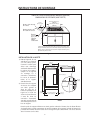
VENTING DOWN
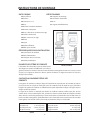
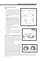
The DCS 36” and 30” downdraft vent system can be
ducted in four different directions; down, left, right or
back using a 3-1/4" X 10" rectangular vent. Fig. 03
illustrates venting options. Fig. 02 shows the ductwork
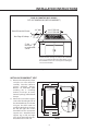
cutout dimensions.
VENTING
LEFT
CALCULATE THE DUCT RUN LENGTH
R H
BACK
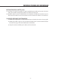
The ductwork length should not exceed 35 equivalent
feet for 3-1/4" X 10" duct, or 60 equivalent feet for 9"
FIG.03 Ducting
round duct. Calculate the length of the ductwork by
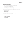
adding the equivalent feet listed in Fig. 04 for each piece
of duct in the complete system. An example is given in Fig. 05. For best results, use no more than
three 90° elbows. Make sure that there is a minimum of 24" of straight duct between elbows if more
than one is used. Do not install two elbows together. Round duct is recommended instead of
rectangular duct especially if elbows are needed. Rectangular duct should transition to round as soon
as possible (6” round minimum).
VENTING
45° Elbow
90° Elbow
90° Flat Elbow
Wall Cap
IG
T
VENTING
9 Feet Straight Duct
2 - 90° Elbows
Wall Cap
Total System
5.0 feet
7.0 feet
12.0 feet
0.0 feet
FIG.04
FIG.05
6
9.0 feet
14.0 feet
0.0 feet
23.0 feet