1
X-HD card – User’s Guide
APOGEE ELECTRONICS
Configuring Pro Tools
X-HD card – User’s Guide
APOGEE ELECTRONICS
Configuring Pro Tools (continued)
Hardware Setup
Working with Delay Compensation
Once clock and DigiLink cables are connected, and all interfaces are properly receiving clock, start
Pro Tools:
Pro Tools provides the H/W Insert Delay Compensation window to add the latency of outboard
hardware to the Delay Compensation Engine when hardware inserts are used. As would be the case
when connecting via 192 Digital interfaces, the latency of Apogee interfaces may be entered into this
window so that hardware inserts via Apogee hardware remain time aligned with other channels.
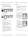
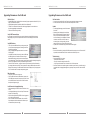
1 In Pro Tools, select Setup>Hardware.
2 From the Peripherals list on the left side of the Hardware Setup window, verify that Apogee interfaces have been detected correctly (as indicated in the Interface Connections Chart
found on pages 10-16).
3 If all interfaces have been correctly detected, select each instance of “192 Digital I/O” displayed,
and click on the “Set to Default” button.
Most settings in the Hardware Setup window are ignored by Apogee hardware, with the exception of
the following:
Peripherals – All Apogee interfaces are detected in the Peripheral list as “192 Digital I/O”, as
indicated by the Interface Connections Chart on pages 9-12.
Clock Source – The Apogee interface connected directly to the HD Core card will respond to the
Clock Source setting.
Port Settings – If this parameter is not greyed out, it must be set to Expansion I/O to detect
multiple Apogee interfaces.
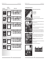
To enter values into the H/W Insert Delay Compensation window:
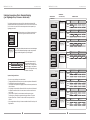
1 Determine the appropriate compensation value from Table 1, based on:
i. The sample rate of the session
ii. The Apogee interface(s) connected (if you’re using an AD and DA-16X both in Advanced routing, please see Table 2).
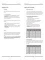
2 In Pro Tools (7.0 or greater), choose Setup > I/O and click on the H/W Insert Delay tab.
3 Each 192 Digital I/O icon corresponds to a detected Apogee interface; enter the
appropriate compensation value in all 16 fields.
4 Repeat for all additional interfaces
5 Though not required, it may be convenient to create and export an I/O Setup for each sample rate you work at. Rather than modify all the Insert Delay settings each time you change sample rates, simply import the I/O Setup with the correct values already stored.
AD&DA-16X
Standard Routing
ROSETTA 800
44.1 kHz
1.31
1.29
Sample Rate
I/O Setup
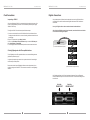
For simplicity, it’s recommend that all paths on the Input, Output and Insert tabs be deleted and reset
to Default. If paths aren’t used by the connected Apogee interface, it’s recommended to delete them.
For clarity, it’s recommended that all paths be re-named to reflect the corresponding Apogee
interface.
For example, 1 Rosetta 800 will be detected as 1 192 Digital I/O in the Hardware Setup>Peripherals
list, resulting in paths A1-16 to be created in the Input, Output and Insert tab pages. On the Input tab,
re-label paths A1-8 as Rosetta In 1-8; On the Output tab, re-label paths A1-8 as Rosetta Out 1-8;
delete paths A9-16 on each page, as they are not active paths.
48 kHz
1.20
1.18
88.2.1 kHz
.40
1.13
96 kHz
.36
1.04
176.4 kHz
.11
1.01
192 kHz
.10
.93
TABLE 1
AD-DA16X Advanced Routing
When using an AD and DA16-X both in Advanced routing, connected to the same PCI card, the available analog I/O is routed to Pro Tools I/O A1-16 and the available digital I/O is routed to Pro Tools I/O
B1-16. Consequently, the compensation values are different for I/O A1-A16 and B1-B16, as shown
below in Table 2.
AD&DA-16X
Advanced Routing Analog
AD&DA-16X
Advanced Routing Digital
44.1kHz
1.29
0.09
48kHz
1.18
0.08
88.2.1kHz
.38
0.06
Sample Rate
96kHz
.34
0.05
176.2kHz
.08
0.03
192kHz
.08
0.02
TABLE 2
8
9