1
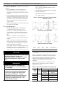
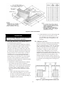
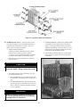
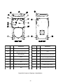
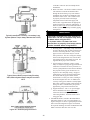
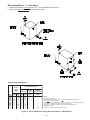
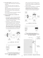
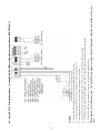
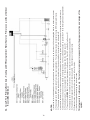
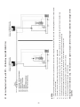
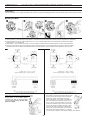
Figure 2: Boiler Foundation
b. If horizontal ducts are used, each opening shall
have a free area of not less than 1 sq. inch
per 2,000 Btuh (70 sq. inch per gph.) (11 cm2
per kw) of total input of all appliances in the
enclosure.
WARNING
Failure to supply adequate air to the boiler
will result in unsafe boiler operation.
D. CHIMNEY OR VENT
C. PROVIDE AIR SUPPLY AND VENTILATION to
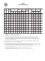
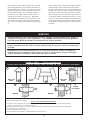
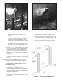
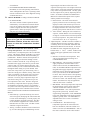
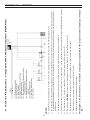
The Series 24 boiler is designed for forced draft firing
and may be used with a conventional natural draft
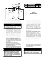
stack (15’ minimum height) or a stub vent, sometimes
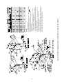
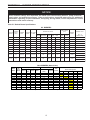
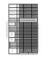
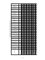
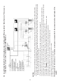
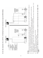
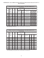
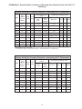
called a diesel stack (see Figure 3a). See Table I for
the proper vent outlet size. For low silhouette vent
terminations, see Figure 3b. Draft controls are not
normally required, although they may be used on
installations where a natural draft stack is used or on
multiple boiler installations with a common stack. The
boiler is provided with a breeching damper, which
should be adjusted to maintain a positive pressure of
0.1” W.C. in the vent connector box during burner high
fire operation (see breeching pressure sensing port in
Figure 1).
accommodate proper combustion.
For commercial and industrial equipment, permanent
facilities for supplying an ample amount of outside air
shall be provided in accordance with the following.
For boiler rooms adjacent to outside walls, and where
combustion air is provided by natural ventilation from
the outside, there shall be a permanent air supply inlet
having a total free area of not less than 1 sq. inch per
4,000 Btu per hr. (35 sq. inch per gallon per hour)
(5.5 cm2 per kw.) of total input rating of the burner or
burners and in no case less than 35 sq. inch (0.425m2).
For boiler rooms not adjacent to outside walls, the
combustion air shall be supplied in a manner acceptable
to the authority having jurisdiction.
1. In the absence of local requirements, the confined
space shall be provided with two permanent
openings, one in or near the top of the room and one
near the bottom. The openings shall communicate
by means of ducts, with the outdoors or to such
spaces (crawl or attic) that communicate with the
outdoors.
a. Where communicating by means of vertical
ducts, each opening shall have a free area of not
less than 1 sq. inch per 4,000 Btuh (35 sq. inch
per gph) (5.5 cm2 per kw) of total input rating of
all appliances in the enclosure.
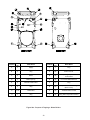
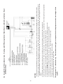
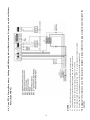
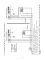
Figure 3a: Typical Arrangement for Stub Vent
11