1
10. Installation
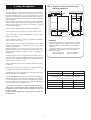
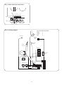
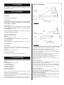
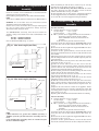
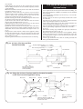
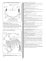
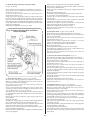
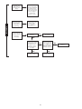
Fig. 15. Flue Options
21/2°
The appliance is supplied suitable for fitting to a sealed
primary system only.
Rear flue
length 100 to
390mm
10.1 Flue Options
NOTE: Flue system
inclines downwards
towards the appliance
Refer to fig. 15.
IMPORTANT
21/2°
Two flue options are available:
Appliance
i) Standard Flue
To suit rear or side flue installations where the flue length
measured from the appliance casing to the outside of the wall
is from 100mm to 1000mm.
Side flue left or
right
length 100 to 36
0mm
Standard Flue
ii) Extended Flue
To suit rear or side flue installations where the flue length
measured from the appliance casing to the outside of the wall
is up to 2000mm.
21/2°
Before continuing the installation it is essential to ensure the
correct flue assembly is available.
Rear flue
maximum length 2000mm
Each flue assembly comprises:
Appliance casing sealing gasket.
Flue turret.
Air duct of appropriate length.
Flue terminal with flue duct, of appropriate length, attached.
Tube of silicon sealant.
Four fixing screws.
(Air duct support bracket, optional extra, part No 7 716 191 024).
NOTE: Flue system
inclines downwards
towards the appliance
21/2°
Appliance
Flue system notes:
Side flue left or right
maximum length 2000mm
Extended Flue
i) Flue incline
The flue assembly must be installed with an incline of 21/2°
(44mm per metre length). The incline must fall towards the
appliance.
Refer to Section 3, Table 2 and fig. 15.
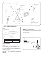
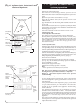
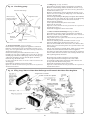
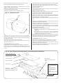
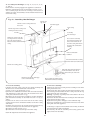
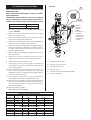
Hold the wall plate on the wall onto which the appliance is to be
fitted. Check the wall plate is horizontal. See fig. 16.
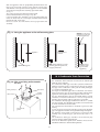
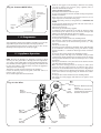
Ensure the plastic cover, over the valves and ‘O’ rings, is left in
place. The cover will protect the valves and ‘O’ rings against
ingress of dirt and dust.
Mark the position of the fixing holes. Two at the top and four
locating the pre-plumbing manifold onto the wall.
Mark the position of the appliance centre-line, from the ‘V’
formed by the wall plate cross member, onto the wall.
Draw a horizontal line along the top of the wall plate cross
member. See fig. 16.
ii) Installation Standard
The flue must be installed as specified in BS 5440 Pt.1.
10.2 General Fitting
Rear Flue Installation
Draw the appliance vertical centre-line on the wall ensure the line
passes through the ‘V’ previously marked.
Measure upwards, along the vertical centre-line, 800mm from
the horizontal line and mark the point. This is the rear flue
centre point position for the flue duct hole. See fig. 16.
NOTE: Read this section fully before commencing the
installation.
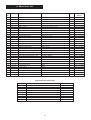
Check the appliance carton contains:
The correct appliance.
Installer’s instruction pack.
User’s instruction pack.
Pre-plumbing manifold.
Wall plate cross member.
Installer’s hardware pack.
Side Flue Installation
Extend the line from the rear flue centre point position,
previously marked, along the appropriate wall.
The line must incline downwards 21/2° (44mm per metre
length) towards the appliance.
Measure 197mm from the junction of the walls and mark a short
vertical line. Extend horizontally the side flue line to intersect the
vertical line and mark the point.
This is the side flue centre point position for the flue duct hole.
See fig. 16.
Remove the packaging from the appliance leaving it to stand
upright on the polystyrene plinth.
Using the two M4 thread forming screws supplied in the
hardware pack assemble the wall plate cross member to the preplumbing manifold. See fig. 16.
Check the position chosen for the appliance is in accordance
with the instructions given in Sections 4 and 5. Also refer to fig. 2.
14