1
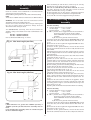
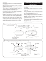
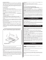
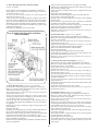
Undo the two upper screws and hinge down the facia, taking
care not to damage the pressure gauge capillary tube or
electrical connections. See fig.27.
Setting the Burner Pressure
Check that all the radiator valves are open.
Set the room thermostat and the Central Heating Temperature
Control to maximum.
Check that the sealed system is pressurised and set to the
required pressure as indicated on the gauge.
Set the Operating switch (or Programmer) to HEATING and
WATER.
Set the gas valve mode switch, located at the rear of the facia, to
the maximum position. See fig. 27.
Turn on a hot water tap.
Turn on the gas and electricity supplies.
A continuous ignition spark will occur until the burner is alight
and sensed by the control circuit. The burner will light and
remain at its maximum domestic hot water setting.
The burner setting pressure should be 11.7 mbar for natural gas
and 35.5 mbar for propane.
Set the gas valve mode switch to the normal position.
Turn both the central heating control knob and the domestic
water control knob to their maximum position (i.e. fully
clockwise).
Turn off the hot water tap.
The burner pressure will drop to minimum setting and will ramp
up to maximum central heating setting. The burner setting
pressure should be 11.7 mbar for natural gas and 35.5 mbar for
propane.
Set the gas valve mode switch to the minimum position.
The burner pressure will drop to the minimum setting for both
central heating mode and domestic hot water mode. The burner
setting pressure should be 0.9 mbar for natural gas or 2.9 mbar
for propane.
Test for gas soundness at the joint between the burner and the
gas valve with leak detection fluid.
Note: The burner setting pressure is factory set and if (after
checking that the supply pressure is sufficient) the correct
pressure is not obtained then The Worcester Service Department
should be contacted. If the appliance does not light, check that it
is not in the ‘lockout’ state by pressing the lockout reset button.
See fig. 31.
Set the gas valve mode switch back to the normal position.
Turn off the electricity supply, and then back on again to reset
the controls.
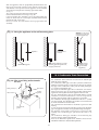
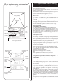
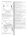
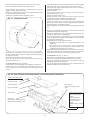
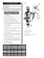
Fig. 28. Pressure Relief Valve.
Turn knob
anti-clockwise
to test
Pressure
relief
valve
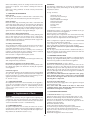
11.2 Programmer
Any programmer fitted on the appliance should be set up at this
stage following the instructions sent with the programmer.
The programmer will retain the setting for up to three weeks
following an interruption in the electricity supply.
11.3 Appliance Operation
NOTE: Because the appliance is designed to operate at high
efficiency the flue gases will be discharged at low temperature.
As a result, a white plume will be emitted continuously from the
flue terminal, when the appliance is operating. This condition will
be more noticeable in cooler weather, even after the appliance
and system have warmed up.
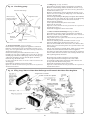
Turn off the gas and electricity supplies to the appliance.
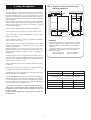
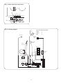
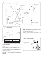
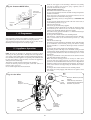
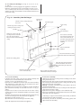
Loosen the burner pressure test point screw and connect a
pressure gauge. See fig. 29.
Access is now required to the mode switch.
.
Max
2mm
Allen key
Fig. 29. Gas Valve
Min
3mm
Allen key
Burner
pressure
test point
Gas valve
sealing
cap
Main gas
valve
connections
Electrical
connections
modulator
(Blue:Blue)
Inlet
pressure
test point
Gas valve
bracket
21
Minimum / Maximum pressure
adjuster rotate Allen key clockwise to
increase and anti-clockwise to
decrease the pressure.