1
Contents
1.
2.
3.
4.
5.
6.
7.
8.
9.
Installation Regulations .............................................. Page 1
Introduction.................................................................. Page 1
Technical Data .............................................................. Page 4
Siting the Appliance .................................................... Page 6
Siting the Flue Terminal .............................................. Page 8
Air Supply .................................................................... Page 8
Sealed Primary Systems ............................................ Page 9
Domestic Hot Water ....................................................Page 10
Electrical ........................................................................Page 10
10.
11.
12.
13.
14.
15.
16.
17.
18.
Installation.................................................................... Page 14
Commissioning ............................................................ Page 19
Handover ...................................................................... Page 22
Inspection and Servicing ............................................ Page 23
Replacement of Parts .................................................. Page 25
Short Parts List ............................................................ Page 34
Operational Flow Diagrams........................................ Page 36
Fault Finding ................................................................ Page 39
Conversion Instructions.............................................. Page 47
1.10 The advice and instructions given in this document covers,
as far as possible, the foreseeable situations which may arise.
Contact Worcester on 08705 266241 for advice on specific
installations.
1. Installation Requirements
1.1 Gas Safety (Installation and Use) Regulations 1998,
as amended, all gas appliances must be installed by a
competent person in accordance with the above regulations.
Failure to install appliances correctly could lead to prosecution.
1.2 The manufacturer’s notes must not be taken, in any way, as
overriding statutory obligations.
1.3 The compliance with a British Standard does not, of itself,
confer immunity from legal obligations. In particular the
installation of this appliance must be in accordance with the
relevant requirements of the Gas Safety (Installation and Use)
Regulations 1998 as amended, current IEE Wiring Regulations BS
7671, local Building Regulations, Building Standards (Scotland)
(Consolidation) and bylaws of the local Water Company. Health
and Safety Document No. 635 (Electricity at Work Regulations). It
should be in accordance with the relevant recommendations of
the following British Standards:
BS 6798: Specification for installation of gas fired hot water
boilers of rated input not exceeding 60 kW.
BS 5449: Central Heating for Domestic Premises.
BS 5546: Installation of gas hot water supplies for domestic purposes.
BS 5440:1: Flues and Ventilation for Gas Appliances of Rated
Input Not Exceeding 60 kW: Flues.
BS 5440:2: Flues and Ventilation for Gas Appliances of Rated
Input not Exceeding 60 kW: Air Supply.
BS 6891: Installation of Low Pressure Gas Pipework Installations
up to 28mm (R1).
BS 5482:1 & 2: Installation of LPG appliances.
BS 6700: Domestic Water Supply in Buildings.
BS 7593: Water Treatment in Domestic Heating Systems.
1.4 To ensure that the installation will perform to the highest
standards, the system and components should conform to any
other relevant British Standards in addition to those mentioned
in the instructions.
1.5. The appliance and/or components conform, where
applicable, with the Essential Requirements of the Gas Appliance
Directive, the Boiler Efficiency Directive, the EMC Directive and the
Low Voltage Directive.
1.6. In accordance with the requirements of COSSH the appliance
does not contain any substances which are harmful to health.
1.7. Product Liability regulations indicate that, in certain
circumstances, the installer can be held responsible, not only for
mistakes on his part but also for damage resulting from the use of
faulty materials. We advise that, to avoid any risk, only quality
approved branded fittings are used.
1.8. LPG Installation. The appliance shall not be installed in a room
or internal space below ground level when it is intended for use
with LPG. This does not preclude the installation into rooms which
are basements with respect to one side of the building but open to
the ground on the opposite side.
1.9 The boiler section contained within this appliance is a
condensing boiler. When in use, the boiler will operate at high
efficiency, emitting a white plume of condensation from the flue
terminal.
A condensate drain point is provided on the appliance.
2. Introduction
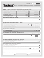
The Benchmark initiative is the new code of practice
to encourage the correct installation, commissioning and servicing
of domestic central heating boilers and system equipment.
The 'checklist' is a vital document that must be completed by
the installer at the time of installation. It confirms that the
boiler has been installed and commissioned according to the
manufacturers instructions.
Without the completion of the checklist, manufacturers may refuse
to respond to a call-out from a householder, who will be advised
that he or she must call back the installer, who has not fulfilled his
obligations to record the information required by the initiative.
It is important that:
The services and the system are properly flushed as specified.
The User is clearly instructed on the correct operation of the
appliance.
The benefits of regular servicing are explained - to maintain the
efficiency and extend the life of the appliance.
2.1 This appliance is not suitable for external installation.
2.2 The appliance controls are set to provide a maximum output
of 26.0 kW in the condensing mode and 24.0 kW in the noncondensing mode for the domestic hot water and central heating load.
2.3 The control circuit provides direct burner ignition. A pilot
light is not used.
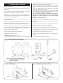
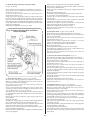
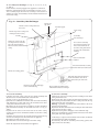
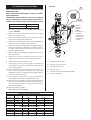
2.4 PRINCIPAL APPLIANCE COMPONENTS
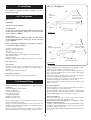
See fig. 1.
A low thermal capacity gas to water main heat exchanger
connected to a secondary high efficiency heat exchanger.
A water to water heat exchanger to provide domestic hot water.
Fully modulating controls in the central heating and domestic
hot water modes of operation.
An expansion vessel, pressure gauge and pressure relief valve.
A by-pass for the central heating system.
Temperature safety cut-out controls.
A water flow regulator.
A standard horizontal flue assembly giving flue lengths from
100mm to 1000mm.
Optional extension flue kit to provide for flue lengths of up to
2000mm.
An internal system filling loop assembly.
Optional facia mounted electronic or mechanical programmers
or a radio controlled room thermostat.
An optional wall spacing frame to allow pipe runs behind the
appliance.
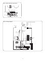
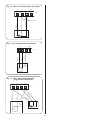
2.5 ELECTRICAL SUPPLY
Mains supply: 230V~, 50 Hz. , 180 watts.
External fuse: 3A (BS 1362).
Internal fuses: T 2A (F1), and T 1.25A (F2).
2