1
2.13 SHOWERS, BIDETS, TAPS AND MIXING VALVES
Hot and cold taps and mixing valves used in the system must be
suitable for operating at mains pressure.
Thermostatically controlled or pressure equalising shower valves
will guard against the flow of water at too high a temperature.
If using a pressure equalising valve, set the Domestic Hot Water
temperature control knob to the “MAX” position.
Hot and cold mains fed water can be supplied direct to an overrim flushing bidet subject to local water company requirements.
With all mains fed systems the flow of water from the individual
taps will vary with the number of outlets operated
simultaneously and the cold water mains supply pressure to the
property. Flow balancing using “Ball-o-Fix” type valves is
recommended to avoid an excessive reduction in flow to
individual outlets. For further information contact The Worcester
Technical Helpline.
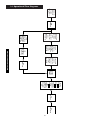
2.15 OPERATION
Hot Water Mode
With a demand for hot water the burner will light at its
maximum setting and then automatically adjust its output to
maintain the temperature of the delivered water. When hot
water is no longer required, the burner will extinguish. The fan
will continue to run for a short period to dissipate the residual
heat from the appliance.
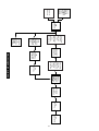
Central Heating Mode
With a demand for heating the burner will light at its minimum
setting and gradually increase to give the maximum output. The
output of the appliance is then automatically adjusted to
maintain the temperature of the system. The output can reduce
down to a minimum of 6.7 kW.
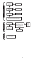
If the system no longer requires even the minimum output to
maintain the desired room temperature the burner will
extinguish. The fan will continue to run for a short period to
dissipate the residual heat from the appliance.
The appliance will remain off for a fixed period of three minutes
before re-lighting to meet the system requirements
automatically.
2.14 SAFETY CONSIDERATIONS
The appliance must not be operated in a waterless condition.
The appliance must not be operated with the boiler inner casing
cover removed.
Work must not be carried out on the appliance without the gas
and electricity supplies being turned off.
Checks must be made to ensure the ventilation openings made into
walls and partitions are of the correct size and are not obstructed.
IMPORTANT: Where back-flow prevention devices, including
water meters, are fitted the expansion of hot water into cold
water main can be prevented. This can result in a pressure
build-up that may cause damage to the boiler and household
devices such as showers, washing machines etc.
In these cases we recommend that a mini-expansion vessel
be fitted adjacent to the boiler in the cold water pipe.
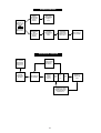
Domestic Hot Water and Central Heating
The appliance will supply heat to the central heating system as
required. A demand for hot water at a tap or shower will
override the central heating requirement for the period of the hot
water demand. When hot water is no longer required the
appliance will return to the central heating state and its normal
mode of operation.
The fan may continue to run to dissipate the residual heat from
the appliance as necessary.
The data plate is fixed to the inner casing cover. Check data plate
to ensure appliance has been adjusted for supply gas.
3. Technical Data.
Table 1.
Mode of
operation
Condense
Non-cond.
Condense.
CH Flow
temp.
°C
50
80
50
Condense
Non-cond
Condense
50
80
50
Nominal Boiler ratings. (10 minutes after lighting).
Boiler adjusted for G20 (Natural Gas).
Burner setting
Output
Input. (Net)
pressure.
KW.
Btu/h.
KW.
Btu/h.
m bar.
in. wg
7.6
(25,930)
7.5
(25,590)
0.9
0.4
24.25
(82,750)
25.25
(86,153)
11.7
4.7
26.0
(88,710)
25.25
(86.153)
11.7
4.7
Boiler adjusted for G31 (Propane).
7.6
(25,930)
7.5
(25,590)
2.9
7.4
24.25
(82,750)
25.25
(86,153)
35.5
14.0
26.0
(88,712)
25.25
(86,153)
35.5
14.0
Gas rate.
ft 3/h.
m 3/h.
0.8
28.3
2.7
95.6
2.7
95.6
0.3
1.03
1.03
10.6
35.4
35.4
G20 Net Input x 1.11 = G20 Gross Input
G31 Net Input x 1.09 = G31 Gross Input
Table 2.
Flue details.
1
Horizontal flue. (N.B: Inclines 2 /2° towards the appliance.)
mm
inches
120 min. to 170 max.
4.5 min. to 6.5 max.
Standard flue. Minimum length
100
4.0
Standard flue. Maximum length
1000
39.4
Extension flue. Maximum length
2000
79.0
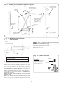
Wall hole diameter. (Diameter increases with wall thickness. See fig 17.)
4