1
AMC
o
ö
PHONES
o
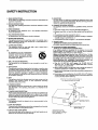
CCVT Integrated A~lfier CVTS030
H.O.M.E. AUTOMATION SERIES
va.l.OE
-ö- 6 ö a-"iJ= 0
L+R
INSTRUCTIONS FOR INSTALLATION AND OPERATION
A
A
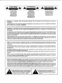
CAUTION: TO REDUCE
THE RISK OF ELECTRIC
SHOCK, DO NOT REMOVE
COVER (OR BACK),
NO USER-SERVICEABLE
PARTS INSIDE. REFER
SERVICING TO QUAUFIED
SERVICE PERSONNEL.
ATTENTION
A' A
AFIN DEV1TER UN
CHOC ELECTRIQUE
ET LES CONSEQUENCES
GRAVES CUI POURRAIENT
EN
~SUlTER,
PARA REDUCIR EL RIESGO
OE SACUDIDAS ELECTRICAS,
NO DEBERA QUITARSE LA
TAPA (NI PARTE POSTERIOR).
CONSULTESE AL PERSONAL
CAPACITADO PARA LAS
REPARACIONES INTERNAS.
TENTEZ
PAS D'OUVRIR L'APPAREIL
ET OE TauCHER AUX
cor.tPOSANTS INTERNES
SAHS LA ~SENCE D'UNE
PERSONNE CUAUFIEE. '
WARNING: TO PREVENT FIRE OR ELECTRIC SHOC!<, DO NOT EXPOSE THIS APPLIANCE TO RAIN OR
MOISTURE.
AOVERTENICIA: PARA EVTTAR EL RIESGO OE INCENDIO 0 SACUDIDA ELECTRICA, NO DEBERA EXPONERSE
ESTE APARATO A LA LLUVIA 0 HUMEDAD.
CAUTION:TO PREVENT ELECTRIC SHOCK DO NOT USETHIS (POLARISED) PLUG WITH AN EXTENSION CORD,
RECEPTACLE OR OTHER OUTLET UNLESS THE BLADES CAN BE FULLY INSERTED TO PREVENT BLADE
EXPOSURE.
ATTENTION: POUR PREVENIR LES CHOCS ELECTRIQUES NE PAS UTILISER CEITE FICHE POLARISEE AVEC
UN PROLONGATEUR. UNE PRISE DE COURANT OU UNE AUTRE SORTIE DE COURANT, SAUF SILES LAMES
PEUVENT ETRE INSEREES A FOND SANS EN LAISSER AUCuNE PARTIE FOND SANS EN LAISSER AUCUNE
PARTIE A DECOUVERT.
PRECAUCION: PARA EVITAR SACUDIDAS ELECTRICAS, NO DEBERA UTILIZARSE ESTA CLAVIJA POLARIZADA
CON UN CORDON DE PROLONGACION, RECEPTACULO U OTRO TIPO OE SALIDA A MENOS QUE SE HAYAN
INSERTASO COMPLETAMENTE LAS LENGÜETAS PARA EVITAR SU EXPOSICION.
NOTE: Some AMC products are equipped with dual or multi-voltage transformers (which is indicated on the back
panel), If you wish to change the voltage, please bring your unit to an authorised AMC service technician for internal
conversion.
a
a
ATTENTION: Quelques pieces AMC sont munies de transformateurs double ou
multi-voltage (indique au
panneau arriere). Si vous voulez changer le voltage, veuillez apporter votre appareil au fournisseur de AMC pour
le transformer.
ZUR BEACHTUNG: Einige AMC Geräte sind mit Umschaltern für unterschiedliche Netzspannungern ausgerüstet
(Ein Vermerk auf der Rückseite weist darauf hin),
Die Anpassung, wenn notwendig, muß von einem qualifizieren Techniker in einer AMC Servicestation vorgenommen
werden.
NOTA: Ciertos componentes de AMC esmn dotados de transformadores de doble tensi6n 0 de va rias tensiones
(10 que se indica en el panel posterior). Si se desea cambiar la tensi6n, sfrvanse lIevar el aparato a un tecnico
autorizado por AMC para su conversi6n interna.
NOTE to CATV systems installer: This reminder is provided to call the CATV system installer's attention to Article
820-22 of the NEC that provides guidelines for proper grounding and, in particular, specifies that the cable ground
shall be connected to the grounding system of the building, as close to the point of cable entry as practical.
NOTA PARA EL INSTALAOOR OE ANTENAS OE TELEVISION COLECTIVAS: La presente advertencia se provee
para lIamar la atenci6n dei instalador al Artfculo 820-22 de NEC (C6rdigo Electrico Nacional) donde se facilitan las
directrices para la pertinente puesta a tierra y que especifica en particular que el condutor a tierra dei cable debe
conectarse al sistema de conexi6n a tierra dei edificio, 10 mas proximo posible al punto de entrada dei cable.
he lightning flash with arrowhead, within an equilateral
~
triangle, is intended to alert the user of the presence of
uninsulated "dangerous voltage" within the product's
enclosure; that may be of sufficient magnitude to
constitute a risk of electric shock to persons,
he exclamation point within an equilateral triangle is
~
intended to alert the user of the presence of
important operating and maintenance (servicing)
instructions in the literature accompanying the
appliance.
INTRODUCTION
INSTAlLATION
The AMC CVT 3030 has been designed to give
superb sound quality and represents
outstanding value for money.
The CVT 3030 is a hybrid mosfet valve design,
capable of giving superb sound reproduction.
The components are all of the highest quality, but
there are a few simple hints to follow in order to
get the best from your new amplifier.
1) 00 not stand any object or other component
on the top. Whilst the 3030 is one of the
coolest running Class A valve amps avallable,
uninterrupted air flow is most important.
2) There are two silent fans in the base under
each pair of EL34 valves. Again, the air space
under the amp must not be restricted in any
way. Never stand the unit on a carpeted
surface or anything soft, or on another
component which generates heat.
3) The amplifier will sound best when it is
'warmed up', this can take 15-20 minutes
avoid operating the PHONES/NORMAL/
OIRECT switch during this period.
4) The valves should last a very lang time but can
be changed easily. However, as there is
always same voltage present inside, even
when the unit is turned off, we recommend
that this is carried out by your AMC dealer, it
is only a five minute job for an engineer.
5) We recommend you retain the original carton
and packaging so that it can be repacked
correctly if it ever becomes necessary to
transport the unit or return for service.
6) After switching off, always let the amplifier cool
down before turning on again.
Your AMC amplifier is supplied set to work on
your local malns supply voltage. Check that
your local mains supply voltage agrees with the
voltage setting indicated on the back panel of the
amplifier. If not, please contact your dealer or
national distributor for details on how to proceed
further.
The cores of the mains lead are coloured in
accordance with the following code:
Blue
- Neutral
Brown
- Live
Note: Export units for certain markets have
moulded mains plugs fitted as standard .
As the colours in the mains lead may not
correspond with the coloured markings
identifying the terminals in your plug, proceed as
fallows:
The wire which is coloured blue must be
connected to the terminal which is marked by the
letter N, or coloured black or blue. The wire
which is coloured brown must be connected to
the terminal which is marked by the letter L, or
coloured red or brown.
FUSES
If the mains plug is fused, fit a 3amp fuse.
Your AMC amplifier contains fuses which are
designed to protect the amplifier and prevent the
occurrence of a dangeraus fault condition.
These should only be inspected and replaced by
a competent engineer using the correct
replacement types.
2
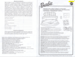
REAR PANEL CONNECTIONS/FRONT PANEL CONTROLS
REAR PANEL
1
"
PttCK)
1»"
CZt
~
-..c _
L~
R -{()------1~o--,~ft_-ft-A
1. PHONO GROUND TERMINAL
2. PHONO MM INPUT
3. DATINPUT
4. CD INPUT
5. TUNER INPUT
6. VIDEO INPUT
7. AUXlUARY INPUT
8. TAPE INPUT
9. TAPE OUTPUT
10. LOUDSPEAKER TERMINALS
11. AC CONVENIENCE OUTLETS
12. AC UNE CORD
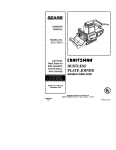
FRONT PANEL
AMC
A~lfier
H.O.M.E. AUTOMATION SERIES
CCVT Integrated
CVT3030
o
VOLlIoE
••ss
1 2
3
1. POWER SWITCH
2. PHONES
3. PHONES/NORMAUDIRECT SWiTCH
4. BASS CONTROL
4
5
6
7
5. TREBLE CONTROL
6. TAPE MONITOR SWITCH
7. INPUT SELECTION SWITCH
8. VOLUME CONTROL
3
8
REAR PANEL CONNECTIONS
DAT
The DAT input is suitable for use with any DAT
player. Connect your DAT player using the
phono socket marked DAT.
A/COUTLET
The AlC convenience outlet is fitted so that other
components can be powered when your
amplifier is switched on. You must fit an
European Standard two pin plug, avallable from
most speciallst dealers.
UNDER NO CIRCUMSTANCES SHOULD THE
CASE OF THE AMPLIFIER BE OPENED BY
ANYONE OTHER THAN A QUALIFIED
ENGINEER, AS DANGEROUS VOLTAGES ARE
PRESENT INSIDE. ANY UNAUTHORISED
REPAIR MAY INVALIDATE YOUR WARRANTY.
TUNER INPUT
The tuner input is suitable for use with most
AM/FM tuners. Connect your tuner to the
amplifier using the phono sockets marked
'Tuner'.
AUXILIARY INPUT
The auxiliary input is suitable for use with any
extra source precessing a line level output
(perhaps a second tuner or CD player, or an
additional tape or video recorder wired for replay
only).
INPUTS
All audio Inputs and tape outputs are via gold
plated RCA type phone connectors. All the
phono sockets on your AMC amplifier are
marked 'L' for lett and 'R' for right channels, with
the left channels nearer the top of the cabinet.
Your connection leads will have a white er black
plug for left, and a red plug for right.
TAPE INPUT
This input is suitable for use with most cassette,
reel to reel or video recorders.
Connect the 'record' leads of your tape recorder
to the phono sockets marked 'Tape out' on the
rear of your amplifier using phono/phono leads.
Connect the 'playback' leads of your tape
recorder to the phono sockets marked 'Tape in'
on the rear of your amplifier using phono/phono
leads.
If your tape machine possesses DIN outputs,
then DIN/phono leads, or a DIN/phono adaptor
can be used. If you experlence level matehing
problems when using DIN connectors, please
consult your tape machine manufacturer.
DISC INPUT
The input is suitable for moving magnet
cartridges only. The plugs on yourturntable lead
should be connected to the disc input sockets
on the rear panel cf your amplifier.
To minimise hum, the turntable lead should be
kept away from the mains wiring, and any
. separate turntable lead should be attached firmly
to the earth terminal on the rear of the amplifier.
. CD INPUT
The CD input is suitable for use with any CD
player. Connect your CD player to the amplifier
using the phono sockets market CD.
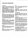
LOUDSPEAKER CONNECTIONS
The loudspeaker output terminals will accept
4mm (banana) plugs, pin connectors, spade
connectors or bare wires.
The amplifier has speaker outputs that will match
4-8 Ohm speakers. Confirm the impedance of
your speakers then connect as folIows:
VIDEO
The video input is suitable for most VCR's with
an audio output. Connect your VCR using the
phono socket marked 'Video'.
4
FRONT, PANEL CONTROLS
For 8 Ohm Speakers, connect the negative
(black) speaker wire to the'common' negative
binding post.
Then connect the positive (red) cable to the 8
Ohm red binding post.
Repeat for the right speaker.
For 4 Ohm speakers, the negative (black)
connections are the same as the 8 Ohm, but the
positive or red connection must be to the 4 Ohm
binding post. Your AMC amplifier is capabIe of
generating high peak currents, so all
connections must be checked to avoid
inadvertent short circuits, and to ensure a good
clean contact.
UNDER NO CIRCUMSTANCES SHOULD BE
OUTPUTS THE SHORTED TOGETHER.
POWER SWITCH
The amplifier is turned on by depressing the
power switch. The small indicator above the
switch will glow green. Before switching on,
always set the volume control to minimum to
avoid damage to your loudspeakers.
Note: Your AMC amplifier will play music almost
immediately after being switched on. However,
in common with other audiophile products, the
internat circuits take some time to stabilise fully,
and the best possible sound quality may not be
obtained until the amplifier has had some time
(possibly an hour or two) to warm up.
INPUT SELECTION
lhe rotary input selector switch selects which
input signal (Phono, CD. Tuner or Aux) is fed to
the power amplifier. The selected signal is also
fed to the 'Tape out' sockets for recording.
TAPE MONITOR SWITCH
The Tape Monitor switch is generally left in the
'Source' position so that the programme
selected by the input switch is routed to the
loudspeakers/headphones. If the Tape Monitor
switch is turned to the 'Tape' position, the signal
from the tape recorder is routed to the
loudspeakers/headphones.
If your tape machine is a three head type suitable
for AlB monitoring, then turning the Tape Monitor
switch to the 'Tape' position will allow full off-tape
monitoring of the recorded signal to be carried
out via the loudspeakers/headphones.
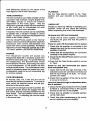
VOLUME CONTROL
The Volume Control is of a split type and allows
you to adjust the levels of the left and right
channels for both loudspeakers independently.
Normally, the two halves of the contral knob
rotate together as they are locked together by a
friction clutch inside the volume control itself.
However, buy holding the rear part of the contral
firmly with the first finger and thumb of one hand,
it is possible to alter the relative position of the
two parts of the knob, and thus compensate for
5
level differences caused by the nature of the
input signal or due to room acoustics.
PLAYBACK
Set the Tape Monitor switch to the 'Tape'
position and your recorder to the playback
mode.
TONE CONTROLS
The tone controls on your AMC amplifier use low
colouration high overload margine (higher then
50V RMS.) circuitry to ensure the minimum
degradation of the music signal. They are
designed to gradually modify the tonal emphasis
of the music and to compensate for such
problems as difficult room acoustics.
If required, the tone controls can be completely
by-passed with a resultant increase in sound
quality. To do this, simply turn the Direct/Phones
switch to the 'Direct' position.
With the Direct/Phones switch in the 'Normal'
position, the tone controls will cut their respective
frequencies when turned anti-clockwise and
boost them when turned clockwise. The flattest
response is found when the controls are in the
'12 o'clock' position. (DETENTED POSmON)
CHECK LIST
Should you have any difficulty in operating your
amplifier, switch off and check the following
before suspecting that a fault has developed:
No power and LED not iIIuminated
1. Check that all mains supplies, connections
and fuses are good and that the power is
switched on.
Power on and LED iIIuminated but no output
1. Check that the amplifier is connected to the
desired input and that the correct input on the
amplifier is selected.
2. Check that the Ioudspeakers are connected
correctly to the power amplifier.
3. Check that the Direct/Phones switch is not set
to 'Phones'.
4.Check that the Tape Monitor switch is not set
to 'Tape'.
Power on and LED iIIuminated but output
from one speaker only
1. Check that the left and right channels of the
selected source are connected correctly and
that the input wiring is not faulty. If in doubt,
contact your dealer.
2. Check that one section of the volume control
is not set to minimum.
Loud hum heard through loudspeakers when
disc Is selected
1. Check that the ground lead from the turntable
(if fitted) is connected firmly to the ground
terminal on the rear of the amplifier.
2. Check that the amplifier is correctly earthed
via the mains lead.
3. Check that other transformers in the vicinity
are not radiating into your amplifier.
PHONES
The headphone socket will accept any
headphones fitted with a standard quarter inch
(6.35mm) stereo jack plug. For private listening
via headphones, the Direct/Phones switch
should be set to 'Phones' , thus cutting the output
to your loudspeakers. In this position the tone
controls remain active. The mute feature is also
useful for situations where the output trom your
loudspeakers needs to be cut momentarily (eg
for a phone call etc).
-TAPE RECORDING
All sourees, Disc, CD, Tuner and Aux can be
-recorded via the tape connections. To record an
input, select the required source and set your
recorder to the record mode.
To record from one tape recorder to another, the
playback recorder should be plugged into the
Aux socket, and the racording machine into the
Tape socket. The input selector switch should
be set to 'Aux'. A recording can now be made
in the normal way.
6
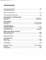
SPECIFICATIONS
Power output into 8/4 ohms ............................................................................................... 30W
With both channels driven
Rated T.H.D. 45Hz-20KHz ................................................................................................ 1.0%
1KHz clipping power into 8/4 ohms .................................................................................... 36W
Input sensitivity for 1W/3OW into 8 ohms:
High level inputs ................................................................................................... 34mV/180mV
Phono input. ......................................................................................................... 0.5mV/2.7mV
Input impedance:
High level inputs ............................................................................................. 20K ohms/100pF
Phono input .................................................................................................... 47K ohms/100pF
Frequency response:
Tone bypass 20Hz-20KHz....................................................................................... + /- 0.5dB
Normal 20Hz-20KHz ................................................................................................ +/-1.0dB
High level inputs -3dB ........................................................................................... 10Hz/80KHz
Signal to noise ratio (ref. 1W/8 ohms):
High level inputs "A" WTD ................................................................................................. 80dB
Phono input HA" WTD ........................................................................................................ 79dB
Separation 20Hz-20KHz ...... ............................................. ..... ......... ............. .............. ... > 50dB
Tone control range:
Bass at 50Hz ............................................................................................................... +/- 8dB
- Treble at 10KHz .......................................................................................................... +/-7dB
r
Overall feedback ................................................................................................................ 14dB
f
Dimensions (WxHxD) ..................................................................................... 430x112x288mm
Net weight.......... ....... ........................................................................................................ 14Kg
Shipping weight.......................................... ............ ........................................................... 15Kg
7
SAFETY INSTRUCTION
1. READ INSTRUCTIONS
All the safety and operating instructions should be read before the
appliance is operated.
2. RETAIN INSTRUCTIONS
The safety and operating instructions should be retained for future
reference.
3. HEED WARNINGS
All warnings on the appliance and in the operating instructions
should be adhered to.
4. FOLLOW INSTRUCTIONS
All operating and use instructions should be followed.
5. WATER AND MOISTURE
The appliance should not be used near water- for example, near a
bathtub, washbowl, kitchen sink, laundry tub, in a wet basement, or
near a swimming pool, etc.
6. CARTS AND STANDS
The appliance should be used only with a cart or stand that is
recommended by the manufacturer.
6A.
An appliance and cart combination
should be moved with care. Quick stops,
excessive force, and uneven surfaces
may cause the appliance and cart
combination to overturn.
7. WALL OR CEILING MOUNTING
This equipment is not designed for use mounted on a wall or a
ceiling.
8. VENTILATION
The appliance should be situated so that its location or position does
not interfere with its proper ventilation. For example, the appliance
should not be situated on a bed, sofa, rug, or similar surface that may
block the ventilation openings; or placed in a built-in installation,
such as bookcase or cabinet that may impede the flow of air through
the ventilation openings.
15. SERVICING
The user should not attempt to service the appliance beyond that
described in the operating instructions. All other servicing should be
referred to qualified service personnel.
16. DAMAGE REQUIRING SERVICE
The appliance should be serviced by qualified service personnel
when:
a) The power-supply cord or the plug has been damaged; or
b) Objects have fallen, or liquid has been spilled into the appliance;
or
c) The appliance has been exposed to rain; or
d) The appliance does not appear to operate normally or exhibits a
marked change in performance; or
e) The appliance has been dropped, or the enclosure damaged.
17. POWER LlNES
(APPLIES TO TUNER AND RECEIVERS ONLY)
An outdoor antenna should be located away from power lines.
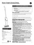
18. OUTDOOR ANTEN NA GROUNDING
(APPLIES TO TUNER AND RECEIVERS ONLY)
H an outside anten na is connected to the receiver, be sure the
anten na system is grounded so as to provide some protection
against vottage surges and built up static charges.
Section 810 cf the National Electrical Code, ANSI/NFPA No. 70-1984,
provides information with respect to proper grounding of the mast
and supporting structure, grounding of the lead-in wire to an antenna
discharge unit, size of grounding conductors, location of
antenna-discharge unit, connection to grounding electrodes, and
requirements for the grounding electrode. See Figure.
a) Use No. 10 AWG (5.3 mm~ copper, No. 8 AWG (8.4mm 2)
aluminum, No. 17 AWG (1.0mm~ copper-clad steel or bronze
wire, or larger, as a ground wire.
b) Secure antenna lead-in and ground wires to house with stand-off
insulators spaced from 4-6 feet (1.22-1.83 m) apart.
c) Mount anten na discharge unit as close as possible to where lead-in
enters house.
2
d) Use jumper wire not smaller than No. 6 AWG (13.3 mm ) copper,
or the equivalent, whena separate antenna-grounding electrode
is used. See NEC Section 810-210).
9. HEAT
The appliance should be situated away from heat sources such as
radiators, heat registers, stoves, or other appliances (including
amplifiers) that produce heat.
Antenna Grounding According to
the National Electrical Code
10. POWER SOURCES
The appliance should be connected to apower supply only of the
type described in the operating instructions or as marked on the
appliance.
11. POWER-CORD PROTECTION
Power-supply cords should be routed so that they are not likely to be
walked on or pinched by items placed upon or against them, paying
particular attention to cords at plugs, comvenience receptacles, and
the point where they exit from the appliance.
Ground
DIscharge
Unlt (~EC
Secllon 810 201
12. CLEANING
The appliance should be cleaned only as recommended by the
manufacturer.
Electric
Groondmg ConduClors
Service
INEC- SecI.on 810-21)
Equlpment
13. NON USE PERIODS
The power cord of the appliance should be unplugged from the outlet
when left unused for a long period of time.
14. OBJECT AND LIQUID ENTRY
Care should be taken so that objects do not fall and liquids are not
spilled into the enclosure through openings.
Antenna
Clamp
~Power
~Natlonal
Electncal Code
Avallable fram Llbrary, book
stores, cr National Fire Protecllon
Associatlon (Batterymarch Park.
Quincy. MA 02269)
Service Groundlng
Beetrode System
(NEC'"" A,. 250 Pa,. H)
WEL TRONICS CORP.
LON DON/L.A.
C 1992 AMC PRINTED IN TAIWAN R.O.C.