1
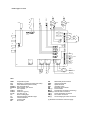
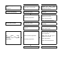
Heaters type 1-2-3-4-5
C
EVG1-II°
EVG1-I°
TR
C
SND
FAN 1
FAN 2
LM
N
I°
J12
II°
SF
F2
J15
J10
LB
N
IMT
J1
LL
J13
J18
RST
J16
MS
TA
J14
J2
J11
J17
J8
J4
J7
RSTR
VM
SE
IGN1
NA
NC
COM
EF
EA1
ION
PA
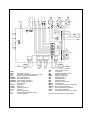
KEY:
SND
TR
LM
EVG1-I°
EVG1-II°
C
FAN 1
FAN 2
F1-F2
LF
LL
LB
RST
EF
Temperature probe
Regulatory control thermostat (auto reset)
LIMIT thermostat (manual reset)
Gas solenoid valve1
Second stage gas valve 2
Fan capacitor
Axial fan 1
Axial fan 2 (type 5)
Line fuse (6,3 A)
Green working light
High temperature indication light
Lockout indication
Lockout reset
Flue venter
PA
IGN1
EA1
ION
SE
IMT (*)
MS (*)
RSTR (*)
TA (*)
VM (*)
SF (*)
Differential pressure switch
Ignition transformer
Spark electrode
Ionisation probe
Electrical control board
Fused isolator
Fire damper connection (accessory)
Remote reset connection
Room thermostat connection
Fan switch connection
Second stage gas valve connection
(*) External to the heater customer supply.
230V 50Hz
J6
L
J9
J5
F1
LF