1
Dynamic Process Controller DPC™ II – User’s Manual
1. AC Power Section
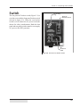
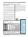
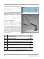
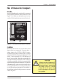
The front-panel AC power section has a switch and
power indicator that is shown in Figure 4-2.
ON/OFF
Green
Power
Indicator
The AC power switch connects AC
power to the generator. This breaker
switch is wired in series with the rear
panel power switch (Figure 3–9). It also
serves as a circuit breaker that provides
overload protection for the DPC. Both
switches must be turned on to supply
AC power to the generator.
Green LED The green indicator above the switch
lights when the DC bus is up, after the
AC power has been switched on. At
this point the generator is capable of
producing an ultrasonic output signal.
Front
AC Power
Switch
Figure 4–2 Front Panel AC Power Section
2. Generator Status Panel
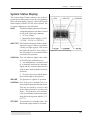
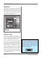
The Generator Status Panel is subdivided into
three sections which provide control and status
displays.
1. Generator Control Keys
2. System Status Display
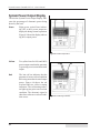
3. System Power Output Display
Status Control Keys
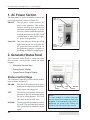
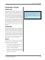
The Generator Control Key section consists of three
keys as shown in Figure 4-3.
ON LINE
TEST
OFF LINE
30
This places the generator in an operational state. It can produce an ultrasonic
output signal when triggered.
The TEST key momentary activates the
generator to provide ultrasound output
for test or setup purposes. TEST will
only work in the ON LINE state.
This key places the generator in a standby mode. This prevents the generator
from producing an ultrasonic output
signal.
ON LINE
Key
TEST
Key
OFF LINE
Key
Figure 4–3 Generator Control Keys
NOTE
If a Press module is installed, these keys
are only active if the Emergency Stop is not
engaged. If the Emergency Stop switch is
depressed, the System Status Display will
not be lit and the Control Keys inactive.
Dukane Manual Part No. 403–558–03