1
MX Protection, Control and Monitoring Features FCD LMENTB2300-01 – 07/08
Figures and Tables
Section Figure 1.1 – MX Control Panel
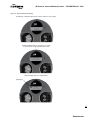
Figure 1.2 – Absolute Position Encoder
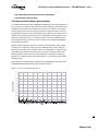
Figure 4.1 – FFT of a sound, efficient worm gear set
Figure 4.2 – FFT of an actuator exhibiting a specific component that is out of tolerance due to
excessive wear.
Figure 4.3 – FDA analysis can be performed at the actuator and is included in its
View Diagnostics menus.
Figure 4.4 – Normal and Diagnostic Displays
Figure 9.1 – Default Configuration Guidelines
Figure 9.2 – Configuring the MX Actuator
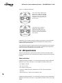
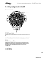
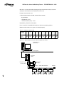
Figure 11.1 – MX terminal block
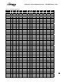
Figure 11.2 – MX wiring diagram matrix
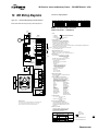
Figure 12.1 – Standard Wiring Diagram for MX Actuators
Figure 12.2 – Optional Features Wiring Diagrams
Figure 12.3 – DDC, Foundation Fieldbus, Profibus DP V1, and Profibus PA,
and DeviceNet Network Wiring Diagrams
Figure 12.4 – DDC, Foundation Fieldbus and Profibus Optional Features Wiring Diagrams
Figure 12.5 – Remote Wiring Connections
Figure 13.1 – Typical Modbus Network Wiring Diagrams – Single Loop
Figure 13.2 – Typical Foundation Fieldbus System with a DCS Host (Daisy Chain Shown)
Table 13.1 – Specifications for the Profibus cable
Table 13.2 – Maximum Segment Length
Figure 13.3 – Typical Profibus System with a DCS Host (Daisy Chain Shown)
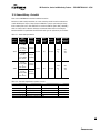
Table 13.3 – Belden Cable Specifications Table 13.4 – Total cable length between repeaters or nodes:
Page
5
7
15
16
16
17
21
22
25
27
29
30
31
32
33
35
36
37
38
38
39
39
3
flowserve.com