1
MX Protection, Control and Monitoring Features FCD LMENTB2300-01 – 07/08
11. Wiring Configurations for the MX
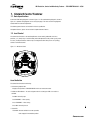
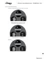
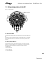
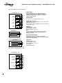
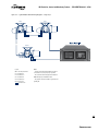
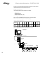
Figure – 11.1 MX terminal block
NETWORK GROUNDING
LUGS
GROUNDING
LUG
11.1 MX Terminal Block
The standard terminal block for the MX now has 54 points and can sustain all of the options for the
MX.
Grounding (earth) lugs are provided for both power leads and network control. It is recommended
that the machined areas adjacent to the terminal block be used to properly ground any network
applications.
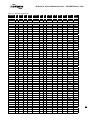
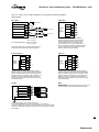
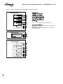
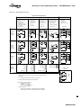
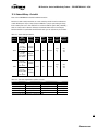
11.2 Wiring Diagram Matrices
The MX now features a number of flexible options that permit a user to customize the electronic
actuator for very specific field applications. The wiring diagram matrix is configured using letters
that correspond to options supplied with the ordered actuator. The code is assembled
(e.g., MXOXX) where:
• MX = family of actuators
• OX = relay configuration
• X = control configurations
25
flowserve.com