1
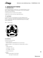
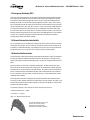
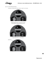
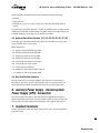
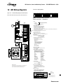
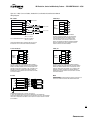
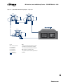
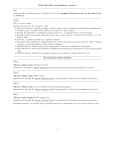
MX Protection, Control and Monitoring Features FCD LMENTB2300-01 – 07/08
Figure 13.1 – Typical Modbus Network Wiring Diagrams – Single Loop
MOV-1
MOV-2
A2
16
A2* 15
Shield
30
41
A2
16
A2* 15
Shield
30
A1
29 A1*
N/C
41
29
N/C
A1
A1*
•
•
•
MOV-250
A1
41
16
29 15
N/C
30
Shield
A1*
A2
A2*
Legend:
Notes:
MOV - Motor Operated Valve
•
A1 -Data Channel 1
connections is necessar y for proper operation.
A1*-Data Channel 1*
•
A2 -Data Channel 2
MOVs will vary up to a maximum of 250.
A2*-Data Channel 2*
•
N/C-No Connection
ground grid.
Correct polarity for field unit and master station
The connections shown are typical. The number of
The ground connection should be a ground rod or
-Shielded cable
35
flowserve.com