1
Superbus Alphanumeric Touchpad
harness wires:
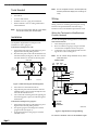
Connect the hardwire sensor to the yellow wires
on the wiring harness as shown in Figure 2.
2.
Wiring the Touchpad to CareTaker EX
Panels
3.
4.
5.
6.
To wire the touchpad’s wiring harness to CareTaker
EX panels:
7.
1.
2.
3.
Turn off the panel power switch.
Run a 4-conductor, 22-gauge or larger stranded
wire from the touchpad location to the panel.
Connect the wires to the panel terminals and wiring harness as shown in Figure 3.
8.
9.
Do not connect wiring harnesses to any touchpads at
this time
Power Up and Bus Communication
Before you power up the panel, you must decide the
unit number (device address) of each bus device
(Alphanumeric Touchpad, HIM, HOM, ESM)
connected to the panel. The panel automatically learns
the unit number of each bus device when you enter the
program mode. All alphanumeric touchpads default to
unit number 1.
Guidelines for Assigning Alphanumeric
Touchpad Unit Numbers
Use the following guidelines to avoid communication
conflicts between bus devices and the panel:
ν
Always start with one touchpad connected to the
panel and get it operational with the panel, before
connecting additional touchpads.
ν
Whenever possible, such as in new installations,
assign alphanumeric touchpad unit numbers
before all other panel programming.
ν
Always work from one touchpad location when
assigning unit numbers for installations with
multiple touchpads.
ν
Other bus devices with unit number DIP switches
(ESM, HIM, HOM, etc.) must be set to the desired
unit number before applying power and entering
the program mode.
Getting One Touchpad Operational With
the Panel
If your installation only calls for one alphanumeric
touchpad, you may proceed with other system
programming.
If you have more alphanumeric touchpads to connect
and assign unit numbers for, use the next procedure
before any other system programming.
Adding Touchpads to Operational Systems
1.
Make sure no new touchpads are connected to
their wiring harnesses.
2. Verify that all wiring at the panel and the added
touchpad wiring harnesses is correct.
3. Set the panel to program mode. Working touchpads display PROGRAM MODE
or-- The display shows ENTER CODE or 1-OFF (1
blinking), indicating you need to enter the install
code).
After entering the install code, working touchpads display PROGRAM MODE.
Note:
4.
5.
6.
7.
1.
Make sure no touchpads are connected to wiring
harnesses.
Choose the touchpad location closest to the panel
and verify that all wiring at the panel and the
touchpad wiring harness is correct.
Make sure panel power is off or removed.
Set the panel to the RUN or NORMAL mode.
Apply power to the panel.
Before connecting the wiring harness to the touchpad, hold the touchpad with one hand so that
your thumb is holding down the 5 button.
Connect the wiring harness to the touchpad with
your other hand. The display shows DA 001 (DA
= device address; 1 = unit number 1).
Set the panel to the program mode and the display should read PROGRAM MODE.
Verify correct operation by pressing STATUS or
BYPASS. The display should show a different
menu item for each button press.
After entering the install code to get into program
mode, the panel allows you to switch between
RUN/NORMAL and PROGRAM mode for one
hour, without re-entering the install code.
At a working touchpad, press BYPASS or STATUS
until the display shows TOUCHPAD OPTIONS.
Press COMMAND and the display shows UNIT
NUMBER.
Press COMMAND and the display shows DA 00N
(DA = device address; N= unit number 0 - 7).
Make a note of this touchpad’s unit number.
Check the unit numbers of all other working
touchpads and write them down.
Page 3