1
User Manual
ASeries A1400DLplus
RS-232 Data Logger
with Battery Backup
the interfacing specialists
A1400DLplus User Manual
Version 1.30
November 2000
COPYRIGHTS
All rights reserved. This document may not, in whole or part, be copied, photocopied,
reproduced, translated, or reduced to any electronic medium or machine readable form
without the express permission in writing from Alfatron Pty Ltd.
Copyright 2000 © Alfatron Pty Ltd
DISCLAIMER
Alfatron Pty Ltd has made every attempt to ensure that the information contained in
this document is accurate and complete. Alfatron Pty Ltd makes no representation or
warranties of merchantability or tness for any particular purpose. Alfatron Pty Ltd reserves
the right to make changes to this document at any time, without notice. Therefore,
Alfatron Pty Ltd assumes no liability for damages incurred directly or indirectly from errors,
omissions or discrepancies with the hardware and the manual.
TRADEMARKS
All Company and Product names are trademarks of the Company or Manufacturer
respectively.
WARRANTY
Alfatron warrants its products against defects in materials and workmanship for a period of
one year from receipt by the customer. All warranty is carried out on a return to depot basis
unless an alternative warranty coverage has been arranged.
WARRANTY EXCLUSIONS
The above warranty shall not apply to defects resulting from improper or inadequate
maintenance by the customer, unauthorised modications or misues, operation outside
the environmental specications for the product, damage due to power surges, lightening
strikes or any other phenomenon outside normal operational specications.
Alfatron Pty Ltd ACN: 005 410 819
P.O. Box 4161
Unit 9/36 New St.
Ringwood VIC 3134
AUSTRALIA
Web Site: www.alfatron.com.au
A1400DLplus User Manual
1.0
PRODUCT DESCRIPTION
The ASeries A1400DLplus Data Logger has one Serial Input, one Serial
Output, a battery backed in-line data buffer. It will accept data through
its independent input port, store the data in its buffer and send it to the
independent output port. It has been specially designed to handle Call
Accounting infromation which is output from PABX equipment but its generic
design makes it suitable for many other applications.
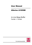
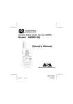
The physical layout of the ASeries A1400DLplus is as follows:
A1400DLplus Data Logger
Power
Error
Data
IN
Data
OUT
Power Cable
for Modem
OUTPUT
Battery
OFF
INPUT
ON
Battery
Selector
Input
Power
Connector
Figure 1 - A1400DL viewed front & rear
The A1400DLplus uses 72-pin SIMM memory for its internal data buffer. The
Input and Output RS-232 Serial ports support baud rate speeds from 300bps
to 115,200bps. Each port may be congured independently and both ports
support Hardware (DTR/DSR) and Software (Robust Xon/Xoff) handshaking
protocols. The Input port may also be switch selected to either DCE or DTE
to simplify cabling requirements.
1.1
How it works with a PABX Telephone System
It addresses two major issues encountered in PABX buffer situations:
1. What happens if equipment collecting the information (lets say a PC)
loses its power. Will the A1400DLplus continue sending out data which
will then be lost?
2. What happens if the PC is powered up after a power loss? When does
the A1400DLplus start sending data to the PC?
A simple in-line buffer does not address either of these problems but the
A1400DLplus has been specically designed to handle these issues.
3
A1400DLplus User Manual
1.2
Operation after Loss of Power
Our standard buffer uses a 10K pull up resistor on the 'DSR' line (Pin 20)
of its Output port to keep this line 'high', enabling transmission of data at
all times. When a PC is connected, this resistor is over-ridden by the 'DTR'
line on the PC, which controls data transmission from the buffer. When the
PC is powered off, the resistor on the buffer takes over again inadvertently
enabling the transmitter and therefore losing data.
The A1400DLplus does not use this resistor on the 'DSR' line, instead it
passes control to its internal driver/receiver chip. This guarantees that the
A1400DLplus transmitter will be disabled when the PC connected to the
output port is powered off.
1.3
Operation after Resumption of Power
This issue is overcome in the rmware of the A1400DLplus. This will only
work if the A1400 Output port is used in Xon/Xoff handshaking mode, (refer
to DIP switch settings in this manual).
When a PC is powered off, the 'DTR' line will go to a 'low' state and disable
the A1400DLplus transmitter, as discussed above. When the PC is powered
on again, one of two things will happen:
(a) If the last character received was an 'Xoff' there is no problem because
the 'Xoff' would disable the A1400DLplus from sending data.
(b) If the last character was an ‘Xon’ then the problem arises that the PC
cannot guarantee that, on power up, it will keep its serial port handhaking
level in a state which will keep the A1400DLplus transmitter disabled.
During the PC power up procedure, its 'DTR' line will remain in a 'high'
state from anywhere between 2 to 30 seconds, depending on the speed
of the PC and how long it takes to boot up. At 9600bps this means that
approximately 1 to 30K bytes of data would be lost.
The A1400DLplus addresses this problem by introducing a special 'Xon
Monitor Timer' feature. This special feature means that it must receive
an 'Xon' at least once every 10 seconds, otherwise it will disable its
transmission.
1.4
Other Considerations
It is advisable to read data out of the buffer in small lots, say 100 bytes or
one line at a time. Every access to the buffer will start with an 'Xon' and
nish with an 'Xoff', ensuring that the buffer stays disabled for most of the
time when the application does not access it. This creates a smaller margin
for data loss due to loss of power by the PC.
4
A1400DLplus User Manual
2.0
INSTALLATION
To prevent battery discharge the A1400DLplus is factory shipped with the
backup battery 'disabled'. For normal operation simply slide the switch at the
rear of the unit to the 'Battery ON' position.
If a 'Modem Power Cable' is installed then connect this to the Modem rst.
Then insert the 4-pin power plug into the power jack socket. Turn the power
ON and observe the LEDs. The ‘Power’ LED should light up and remain
alight, all other LEDs should light up and then extinguish within 2 seconds.
After this sequence the A1400DLplus is ready for operation.
Power OFF the A1400DLplus and connect the correct cables between
it and the target devices. Use only cables which you know to have the
correct pin congurations. Pin assignments and Cable requirements are
discussed in Sections 4 and 5.
WARNING: All devices must be powered OFF before connecting cables to
them. Incorrect cabling may cause damage to either the A1400DLplus or
your equipment and is not covered by warranty.
2.1
How to RESET the A1400DLplus
Once the battery has been enabled the A1400DLplus cannot be hardware
reset by disconnecting the power adapter. The following procedure must
be used instead:
l Move the Battery Selector to the 'Disable' position (factory setting)
l Remove power jack from the unit and wait for 5 seconds
l Move the Battery Selector to the 'Enable' position and insert power jack
2.2
Power Up Self Test Feature
During power up sequence described above the A1400DLplus performs
a Power Up Self Test:
l The Static RAM (SRAM) is checked for any errors. If an error occurs
during this test the unit will enter ‘SRAM Error Mode’ and is indicated
by the LEDs ‘Receive Data’, ‘Transmit Data’ and ‘Data Error’ all ashing
simultaneously. This indicates that the A1400DLplus has a fault.
At the end of a normal Power Up Self Test the ‘Power’ LED only will remain
alight and the unit is ready for normal operation.
5
A1400DLplus User Manual
3.0
CONFIGURATION OF RS-232 SERIAL PORTS
3.1
Location of Serial Conguration Switches
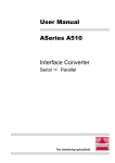
The following diagram shows the location of the various switches on the
A1400DLplus Printed Circuit Board (PCB). These switches can only be
accessed with the cover removed as shown here:
DIPSW2
(Output)
SIMM Socket
DIPSW1
(Input)
DCE< >DTE
Select Switch
Hardware
Handshake
Select
Serial
OUTPUT
Serial
INTPUT
Figure 3-1. Location of Switches on Printed Circuit Board
3.2
Setting the DIP Switch
The A1400DLplus has an independent DIP switch bank on the PCB for each
of the ports, see Figure 3-1 above.
Before changing the DIP switch settings, move the 'Battery Selector'
to the 'Disable' position and disconnect the power supply. Change the
settings as required and then 'Enable' the battery and re-insert the supply
3.3
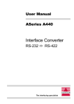
Factory DIP Switch Settings
INPUT and OUTPUT DIP Switches are factory pre-set as follows
9600 bps
8 Data Bits
ON
No Parity
DTR/DSR Hardware Handshaking
1 Stop Bit
6
1
2
3
4
5
6
7
8
A1400DLplus User Manual
3.4
DIP SWITCH SETTINGS
Table 3-1
Switch
Function
OFF
ON
1
2
Baud Rate Setting
S e e Ta b l e 3 - 2 b e l o w
3
Data Bits
4
5
6
7
Pa r i t y & Te s t M o d e
8
S e e Ta b l e 3 - 3 b e l o w
7
Handshaking
H a r d wa r e
Xon/Xoff
8
Stop Bits
1
2
Table 3-2
Switch
300
1200
2400
9600
19,200
38,000
57,600
115,200
1
Off
On
Off
On
Off
On
Off
On
2
Off
Off
On
On
Off
Off
On
On
3
Off
Off
Off
Off
On
On
On
On
Table 3-3
3.5
Switch
Odd
Even
None
Te s t
5
Off
On
Off
On
6
On
On
Off
Off
DCE / DTE Input Port Selection
To make cabling easier the Input Serial port may be switch selected as
either DCE or DTE. The slide switch is located on the printed circuit board
behind the serial port connector. The diagram below shows the switch
set to the DCE selection:
DCE < > DTE
7
A1400DLplus User Manual
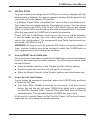
3.6
Hardware Handshake Selection
The hardware handshake pair on the INPUT serial port may be jumper
selected as either DTR/DSR or RTS/CTS.
DSR
DTR
4.2.1 Input Port
The jumpers J1 and J2 are located directly
behind the Input serial port connector.
l
l
J1 is used to select either CTS or DSR
J2 is used to select either RTS or DTR
CTS
RTS
J1
J2
The diagram above shows the selection of the DTR/DSR handshake pair.
3.7
EXPLAINING SERIAL FLOW CONTROL (Handshaking)
3.7.1 Hardware (DTR/DSR) Handshaking
Hardware DTR/DSR handshaking uses the Data Terminal Ready (DTR)
and Data Set Ready (DSR) signal lines to control the ow of data between
devices.
On the A1400DLplus, DTR is an output signal line which is ready to receive
data when the RS-232 level is 'high', greater than +3Volts. Conversely, a
DTR 'low', less than -3Volts, indicates that the unit is temporarily unable
to receive data.
DSR is an input signal line which controls the output of the A1400DLplus.
A 'high' RS-232 level, greater than +3Volts, indicates that data may be sent
to the connected device. A 'low' RS-232 level, less than -3Volts, indicates
that data cannot be sent to the connected device. Hardware DTR/DSR is the
preferred method of handshaking under the DOS operating system.
8
A1400DLplus User Manual
3.7.2 Software (Xon/Xoff) Handshaking
Software Xon/Xoff handshaking uses the ‘Xon’, HEX(11), and ‘Xoff’, HEX(13),
ASCII characters to control the ow of data. When using Xon/Xoff with RS-232
levels, always leave DTR/DSR disconnected on the A1400DLplus.
Standard Xon/Xoff performs handshaking in both directions by sending ‘Xon’
and ‘Xoff’ to the connected device and detecting these characters being
sent from the connected device. The ‘Xon’ and ‘Xoff’ are sent only once. If a
device connected to the A1400DLplus misses an 'Xoff' (due to corruption by
electrical noise), this device will continue to send its data and overow the
buffer of the A1400DLplus. Alternately, if this device misses an ‘Xon’ from
the A1400DLplus, a ‘lock-up’ situation will occur whereby the A1400DLplus
is ready to receive data, the device is ready to send data but the ‘Xon’
character was missed. In this ‘lock up’ state, both devices are waiting for
each other to send something. To overcome this ‘lock up’ state, Robust
Xon/Xoff handshaking is used.
3.7.3 ROBUST Xon/Xoff
Robust Xon/Xoff handshaking overcomes limitations in the Standard Xon/Xoff
protocol by repeatedly sending the ‘Xon’ or ‘Xoff’ character.
For example, if an ‘Xoff’ is sent from the A1400DLplus to a connected device
and it is corrupted, it will not matter. In Robust Xon/Xoff mode the ‘Xoff’
character will be sent to that device each time a character is received past
the cut-off point of the A1400DLplus’s buffer.
When the A1400DLplus is ready to receive data, an ‘Xon’ character will
be sent repeatedly to ensure that the connected device may resume data
transmission. If only a single ‘Xon’ character is sent, as in Standard Xon/Xoff,
there is the possibility of corruption and the ‘lock up’ state would occur, the
A1400DLplus having sent an ‘Xon’ and awaiting data and the connected
device awaiting an ‘Xon‘ before sending data.
Due to the UNIDIRECTIONAL nature of the A1400DLplus, Robust Xon/Xoff
is implemented only on the INPUT port (Port 1).
9
A1400DLplus User Manual
4.0
SERIAL PORT PIN ASSIGNMENTS
4.1
RS-232 Pin Assignments
Pin
Status
DCE
1
2
3
4
5
6
7
8
20
22
Ground
Input / Output
Output / Input
Used - Pulled High
Used - Pulled High
Used - Pulled High
Ground
Not Used - Pulled High
Used
Not Used - Pulled High
Note:
Output Port is xed as DCE
DTE
FG
RD
TD
CTS
RTS
DTR
SG
DCD
DSR
RI
5.0
CABLE REQUIREMENTS
5.1
Cable Shielding
FG
TD
RD
RTS
CTS
DSR
SG
DCD
DTR
RI
Alfatron recommends using shielded cable with all its products. Shielding
reduces Electro Magnetic Radiation and improves noise immunity. This helps
minimise interference to other equipment and will improve communications
reliability.
The recommended cable construction is as follows:
l Take the shield (surrounding cable wires) and solder it to the Frame Ground (FG)
pin. If FG is not available, use Signal Ground (SG) but in this case always use a
separate wire for ground which is connected at both ends.
l The shield must be connected at both ends of the cable.
5.2
Cable Examples
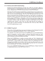
5.2.1 RS-232 Connection to a PC with a DB-25 Serial Connector
Shield
A1400DLplus
Cable End
DCE
(DB-25 Male)
10
FG
RD
TD
CTS
RTS
DTR
SG
DCD
DSR
1
2
3
4
5
6
7
8
20
1
2
3
4
5
6
7
8
20
FG
TD
RD
RTS
CTS
DSR
SG
DCD
DTR
PC Cable End
DTE
(DB-25 Female)
A1400DLplus User Manual
5.2.2 RS-232 Connection to a PC with a DB-9 Serial Connector
A1400DLplus
Cable End
DCE
(DB-25 Male)
Shield
RD
TD
CTS
RTS
DTR
SG
DCD
DSR
3
2
7
8
6
5
1
4
2
3
4
5
6
7
8
20
TD
RD
RTS
CTS
DSR
SG
DCD
DTR
PC Cable End
(DB-9 Female)
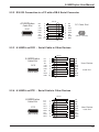
5.2.3 A1400DL as DCE - Serial Cable to Other Devices
Shield
A1400DLplus
Cable End
DCE
(DB-25 Male)
FG
RD
TD
CTS
RTS
DTR
SG
DCD
DSR
1
2
3
4
5
6
7
8
20
FG
TD
RD
RTS
CTS
DSR
SG
DCD
DTR
User Device
Cable End
5.2.4 A1400DL as DTE - Serial Cable to Other Devices
Shield
A1400DLplus
Cable End
DTE
(DB-25 Male)
FG
TD
RD
RTS
CTS
DSR
SG
DCD
DTR
1
3
2
5
4
20
7
8
6
FG
RD
TD
CTS
RTS
DTR
SG
DCD
DSR
User Device
Cable End
11
A1400DLplus User Manual
6.0
CONFIDENCE TESTING THE A1400DL
The A1400DLplus incorporates two Self Diagnostic features designed to
assist with an installation when troubleshooting is required. These features
will assist in establishing the correct operation of the A1400DLplus before
connecting to other equipment. Both tests are described below.
6.1
Character Generation Function Test
The Character Generation Function Test will output a continuous stream of
printable ASCII characters from both the Input and Output ports. This function
may be used to condence test both ports of the A1400DLplus or test the
operation of attached devices. It is activated in the following manner:
1. Power OFF the unit, "disable' the battery and then make a note of the
original DIP Switch settings of the A1400DLplus.
2. Select 'Test Mode' on the DIP Switch of the INPUT port only. Refer to
tables 3-1 and 3-3 in this manual for these switch settings.
3. Congure the Input and Output serial ports via the DIP Switches. Ensure
that the cable pinouts are correct for all attached equipment. Ensure that
attached equipment is congured to match the port of the A1400DLplus
and is able to receive ASCII characters.
4. Power ON the A1400DLplus. The Yellow Power LED and the Green
Transmit LED will light and the A1400DLplus will produce a continuous
stream of output as follows:
01234567890:;<=>?@ABCDEFGHIJKLMNOPQRSTUVWXYZ[\]^_’abcedfghijklmnopqrstuvwxyz{|}~
01234567890:;<=>?@ABCDEFGHIJKLMNOPQRSTUVWXYZ[\]^_’abcedfghijklmnopqrstuvwxyz{|}~
01234567890:;<=>?@ABCDEFGHIJKLMNOPQRSTUVWXYZ[\]^_’abcedfghijklmnopqrstuvwxyz{|}~
01234567890:;<=>?@ABCDEFGHIJKLMNOPQRSTUVWXYZ[\]^_’abcedfghijklmnopqrstuvwxyz{|}~
01234567890:;<=>?@ABCDEFGHIJKLMNOPQRSTUVWXYZ[\]^_’abcedfghijklmnopqrstuvwxyz{|}~
01234567890:;<=>?@ABCDEFGHIJKLMNOPQRSTUVWXYZ[\]^_’abcedfghijklmnopqrstuvwxyz{|}~
This output will continue for as long as the A1400DLplus is powered
ON. To stop the continuous output stream simply power OFF the
A1400DLplus.
5. Power OFF the A1400DLplus and re-congure it for normal use using
the DIP Switch settings noted in Step 1 above. 'Enable' the battery and
restore power for normal operation.
12
A1400DLplus User Manual
6.2
DRAM Condence Test
This test will detect and display the buffer memory (SIMM) size and then
proceed to perform a memory test, taking approximately ten minutes for
each 4MB. Therefore this test is not recommended unless the buffer memory
is suspected of being faulty.
Test results will be sent to the INPUT serial port and will repeat as long
as the A1400DLplus is powered on. The test is activated in the following
manner:
1. Power OFF the unit, "disable' the battery and then make a note of the
original DIP Switch settings of the A1400DLplus.
2. Select 'Test Mode' on the DIP Switch of the OUTPUT port only. Refer to
tables 3-1 and 3-3 in this manual for these switch settings.
3. Congure the INPUT serial port via the DIP Switches. Ensure that cable
pinouts are correct for all attached equipment. Ensure that attached
equipment is congured to match the port of the A1400DLplus and is
able to receive ASCII characters.
4. Power ON the A1400DLplus. The Yellow Power LED and the Green
Transmit LED will ash for each 64KB of buffer memory tested. The
following message will be output from the INPUT serial port and
displayed/printed on any attached equipment:
Random DRAM test DRAM_SIZE = 'size' KB
Where 'size' is the total size of SIMM Memory installed. If no SIMM
Memory is installed then the displayed size will be '0'. This message
will be repeated.
The Memory Test has four distinct stages. First the buffer memory is
cleared, then loaded with random test values, held for 5 seconds and
nally veried. This cycle is then repeated. The INPUT serial port will
display this information with one line of data for each 64KB of buffer
memory tested.
13
A1400DLplus User Manual
If a problem is detected with the memory the INPUT serial port will display
the memory location, expected contents and corrupted value. The
test will continue until the end of that stage and the INPUT serial port
will display:
Self test failed on pass 'XX'
Where 'XX' is the number of times the buffer test has completed. The
test will stop and the Transmit and Error LEDs will ash rapidly. This test
will continue for as long as the A1400DLplus is powered ON. To stop the
Buffer Memory Test simply power OFF the A1400DLplus.
5. Power OFF the A1400DL and re-congure it for normal use using the DIP
Switch settings noted in Step 1 above. 'Enable' the battery and restore
power for normal operation.
14
A1400DLplus User Manual
7.0
SPECIFICATIONS
CPU:
Buffer Size:
RS-232 Serial Ports:
LED Indicators:
Power Supply:
Z8S180 Microprocessor @ 18.432MHz
4Mb, 8Mb, 16Mb and 32Mb via 72-pin SIMMs,
STD/EDO, No Parity
RS-232C (CCITT V.24)
Input is switch selectable DTE / DCE
Input is jumper selectable DTR / DSR or CTS / RTS
Output port is xed as DCE
DB-25 Female connector
DIP Switch selection of:
l 300 to 115,200 bps baud rate
l 7 or 8 Data Bits
l None, Odd or Even Parity
l Hardware or Xon/Xoff handshaking
Power On
Receive Data
Transmit Data
Data Error
Dual Power Supply 16V (750mA) DC
and 9V (500mA) DC
PCB is fuse & reverse polarity protected
Plug jack - 4-pin mini power DIN
16VDC
0VDC
Battery:
Dimensions:
9VDC
0VDC
Rechargeable Sealed Lead-Acid
12V, 2.2Ah/20HR
Intelligent battery charging circuit
12 hour memory storage time
47mm x 199mm x 201mm
Weight:
1850 grams
Operating Temperature:
10° to 35° C
Storage Temperature:
(Yellow)
(Green)
(Green)
(Red)
0° to 45° C
All specications subject to change without notice
15
N42
DECLARATION OF CONFORMITY
according to the European Commissions EMC Directive 89/336/EEC
We,
of,
Name of Manufacturer:
Address of Manufacturer:
Australian Company Number:
ALFATRON PTY. LTD
UNIT 9, 36 NEW ST.
RINGWOOD VIC 3134
AUSTRALIA
ACN: 005 410 819
declare under sole responsibility that the product:
Product Name:
ASeries A1400DLplus Data Logger
with Battery Backup
Model Number:
A1400DLplus
to which this declaration relates is in conformity with the following standards:
CISPR-22 / EN 55022 class B
IEC 801-2 / prEN55024-2
IEC 801-3 / prEN55024-3
IEC 801-4 / prEN55024-4
EMI from Information Technology Equipment (ITE)
Electro Static Discharge Immunity
Radiated RF Immunity
Electrical Fast Transients Immunity