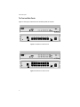
1
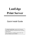
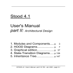
FastHub8 FastHub16 Dual Speed Ethernet Hubs Installation Guide PN 613-10783-00 Rev B Copyright 1999 Allied Telesyn International, Corp. 960 Stewart Drive Suite B, Sunnyvale CA 94086 USA All rights reserved. No part of this publication may be reproduced without prior written permission fro Allied Telesyn International, Corp. Ethernet is a registered trademark of Xerox Corporation. All other product names, company names, logos or other designations mentioned herein are trademarks or registered trademarks of their respective owners. Allied Telesyn International, Corp. reserves the right to make changes in specifications and other information contained in this document without prior written notice. The information provided herein is subject to change without notice. In no event shall Allie Telesyn International, Corp. be liable for any incidental, special, indirect, or consequential damages whatsoever, including but not limited to lost profits, arising out of or related to this manual or the information contained herein, even if Allied Telesyn International, Corp. has been advised of, known, or should have known, the possibility of such damages. FCC Compliance Statement This device complies with Part 15 of the FCC rules. Operation is subject to the following two conditions: 1. The device may not cause harmful interference and 2. This device must accept any interference received, including interference that may cause undesired operation. This equipment has been tested and found to comply with the limits for a Class B digital device, pursuant to Part 15 of the FCC Rules. These limits are designed to provide reasonable protection against harmful interference when the equipment is operated in residential installation. This equipment generated, uses, and can radiate radio frequency energy and if not installed and used in accordance with the instruction manual may cause harmful interference to radio communications. However, there is no guarantee that interference will not occur in a particular installation. If this equipment does cause harmful interference to radio or television reception, which can be determined by turning the equipment off and on, the user is encouraged to try to correct the interference by one or more of the following measures: ❑ Reorient or relocate the receiving antenna. ❑ Increase the separation between the equipment and receiver. Connect the equipment into an outlet on a circuit different from that to which the receiver is connected. Consult the dealer or an experienced radio TV technician for help. Notice: 1. The changes or modifications not expressly approved by the party responsible for compliance could void the user’s authority to operate the equipment. Shielded interface cables and AC power cord, must be used in order to comply with emission limits. iii Table of Contents FCC Compliance Statement.............................................................................. iii Chapter 1 Product Description ...................................................................................... 1 Key Features....................................................................................................... 1 The Front and Back Panels................................................................................ 2 Front Panel LEDs........................................................................................ 3 Back Panel LEDs......................................................................................... 3 Chapter 2 Installation ...................................................................................................... 5 Verifying the Package Content .......................................................................... 5 To Place a Single LanEdge Product on a Desktop..................................... 6 To Wall Mount a LanEdge Product ............................................................ 6 To Interlock a Group of LanEdge Products on a Desktop......................... 7 Powering on the Hub.......................................................................................... 9 Connecting Cables ............................................................................................ 10 Station Connections .................................................................................. 10 Hub to Hub Connections ........................................................................... 10 Chapter 3 Troubleshooting ........................................................................................... 11 No Power ........................................................................................................... 11 Link/Activity LED ............................................................................................ 11 100M LED ......................................................................................................... 12 Connectivity Testing ........................................................................................ 12 Appendix A FastHub8 and FastHub16 Specifications ............................................... 13 Appendix B LanEdge FastHub8 and FastHub16 Installation Guide Feedback ... 15 Appendix C Technical Support Fax Order ................................................................... 17 Incident Summary ............................................................................................ 17 Appendix D Where To Find Us ......................................................................................... 19 v Chapter 1 Product Description The LanEdge FastHub8 and FastHub16 are 10/100 Mbps dual speed hubs for small or medium business applications. With 8 or 16 10/100 Mbps plug-andplay dual speed ports, the hubs support both 10 Mbps and 100 Mbps devices in a single network. The internal switching function provides network connectivity between the two speeds, thereby offering a high level of network flexibility and efficiency. Installation and operation are user-friendly and no configuration is required. Front panel LEDs display network status. The fullrange power supply is suitable for use worldwide. Key Features ❑ Complies with 10Base-T, 100Base-TX specifications of the IEEE 802.3 and IEEE 802.3u standard ❑ Compact size, can interlock with other LanEdge products ❑ Port 8 supports the uplink function with a crossover switch ❑ Auto-negotiation, 10 Mbps, or 100 Mbps speed is manually set for Port 1 and Port 2 by DIP switches ❑ Power and status LEDs provide instant status ❑ Supports 1792 MAC addresses ❑ Supports 120,000 bytes of packet buffering (60 packets) ❑ VLAN Tag 802.1Q pass through mode between segments ❑ Extra long length packet (up to 2016 bytes) pass through mode between segments ❑ 10Base-T/100Base-TX auto-negotiate for speed detection ❑ External power adapter, U.S., Europe, England Note All ports operate in half-duplex mode only. 1 Product Description The Front and Back Panels Figure 1 and Figure 2 show the front and back panels of the hub. 1 2 3 4 Figure 1 FastHub8 Front and Back Panels 1 2 3 4 Figure 2 FastHub16 Front and Back Panels 2 FastHub 8 and FastHub 16 Installation Guide Front Panel LEDs Power. Indicates that the hub is receiving power and is operational. Collision 10M/100M. Each unit has two Collision LEDs: 10M indicates a collision on the 10 Mbps segment, and 100M indicates a collision on the 100 Mbps segment. A collision occurs when two stations within a collision domain attempt to transmit data at the same time. The contending adapters resolve each collision by means of a wait-then-retransmit algorithm. Intermittent flashing of the Collision LED is normal. Frequency of collisions is an indicator of heavy traffic on the network. 100M. When lit this LED indicates the port is operating and/or configured (Ports 1 and 2) at 100 Mbps. When the LED is OFF (not lit), the port is operating and/or configured at 10 Mbps. Each port has a 100M LED. Link/Activity/Error. Steady green (Link state) indicates that the port has good linkage to its associated device. Flashing green (Receive state) indicates that the port is receiving data from its associated device. Flashing yellow indicates that an error occurred and that the port is partitioned. Each port has a Link/ Activity/Error LED. Back Panel LEDs Connectors, the Port 1 and 2 speed DIP switch and the uplink switch are on the back panel of the hub. Speed DIP Switch. This DIP switch manually selects auto-negotiation, 10 Mbps, or 100 Mbps speed for Port 1 and Port 2. Figure 3 shows an close-up of the DIP switch setting. In the example below, Port 1 is in the Auto position and Port 2 is in the 100M position. 1 2 3 4 Figure 3 Close-up of DIP Switch Setting Ethernet Ports. The hub has 8 or 16 ports located on the back panel; all are autonegotiating, dual speed 10Base-T/100Base-TX ports. 3 Product Description Uplink Switch. The slide switch located on the right side of the back panel is for the uplink function. To use Port 8 as an Uplink port, manually set the switch to the “Uplink” position. This eliminates the need for a crossover cable when connecting directly to another hub. Power Connection. For compatibility with electric service in most areas of the world, the hub two-piece power adaptor automatically adjusts to line power range 100~220 VAC and 50~60 Hz. Per ordering option, a country specific power receptacle cord is also supplied with your hub. 4 Chapter 2 Installation The hub does not require software configuration, and is ready to work by simply attaching the cables and power adapter. This chapter provides information and procedures to install the unit. Verifying the Package Content Before you start installation, please check the contents of the package. The product package should include the following: ❑ One FastHub8 or FastHub16 unit ❑ Accessory bag containing rubber feet and bumpers for desktop placement, and screws for wall mounting the unit ❑ A two-piece AC Power adapter (DC 5V) consisting of a country specific AC receptacle cord and universal power supply ❑ This installation guide ❑ Warranty Card If any item is missing, please contact your Allied Telesyn representative. Allied Telesyn locations can be found in Appendix D on page 19. 5 Installation Placing the Hub You can wall mount a single LanEdge product, place it on a desktop, or interlock two or more to form a single unit that occupies only one footprint on the desktop. Caution Air vents must not be blocked and must have free access to the room ambient air for cooling. To place your LanEdge product, see the steps that follow: ❑ “To Place a Single LanEdge Product on a Desktop” on page 6. ❑ “To Wall Mount a LanEdge Product” on page 6. ❑ “To Interlock a Group of LanEdge Products on a Desktop” on page 7. To Place a Single LanEdge Product on a Desktop 1. Place the unit up-side down. 2. Locate the rubber feet and bumpers from the accessory bag. Remove the paper cover from the adhesive and press a rubber foot into each round receptacle on the bottom of the unit. Remove the paper cover from the adhesive and press a rubber bumper into each square receptacle on the bottom of the unit. 3. Put the unit on the desktop. Skip to “Powering on the Hub” on page 9. To Wall Mount a LanEdge Product 1. Do not install the rubber feet or bumpers if you are wall mounting the product. If you previously installed the square rubber bumpers, remove them using the following step. (The round rubber feet need not be removed.) ❑ To remove the square rubber bumper from the unit: Place the unit upside down. For each bumper, insert the tip of a small straight-slot screwdriver between the rubber bumper and the unit casing. Press down on the screwdriver to pry the bumper off. 2. Prepare the wall by installing two screws (provided) at 9 1/4-inch (23.5 cm) apart on center. 3. Position the unit onto the screws. Skip to “Powering on the Hub” on page 9. 6 FastHub8 and FastHub16 Installation Guide To Interlock a Group of LanEdge Products on a Desktop The interlocking feature of the LanEdge products makes it easy for you to install the units on a desk or table. You can place the units on top of each other and interlock them to form a stack. A stack can consist of any combination of LanEdge hubs. It is recommended that the heaviest unit be placed as the base (bottom) unit. For example, if you are installing a LanEdge FastPrint Server, place it as the base unit; otherwise, if you are installing a LanEdge OmniConnect, place it as the base unit. 1. Select the base unit and place it up-side down on a work surface. Locate the rubber feet and bumpers from the accessory bag. Remove the paper cover from the adhesive and press a rubber foot into each round receptacle on the bottom of the unit. Remove the paper cover from the adhesive and press a rubber bumper into each square receptacle on the bottom of the unit. 2. Place each of the other units up-side down on a work surface. Locate the rubber feet and bumpers from the accessory bag. Do not install the square rubber bumpers. Remove the paper cover from the adhesive and press a round rubber foot into each round receptacle on the bottom of the unit. Note The LanEdge products will not interlock properly if the square rubber bumpers are installed on the interlocking (upper) unit; install these bumpers only on the base unit. 3. Place the first LanEdge unit on the desktop as the base. If you are installing a FastPrint Server, place it as the base (bottom) unit; otherwise, if you are installing a OmniConnect, place it as the base unit. 7 Installation 4. Pry off the interlock cap at each corner of the unit. Refer to Figure 4. From the side of the unit, insert the tip of a small straight-slot screwdriver into the opening of the interlock cap. Press down on the screwdriver to pry the cap off. Figure 4 Interlock Cap 5. Place the next unit over the base unit, aligning with the interlock cap and press down on each corner to snap the units together. 6. Repeat steps 4 and 5 until all units are in the assemblage. 7. Continue with “Powering on the Hub.” 8 FastHub8 and FastHub16 Installation Guide Powering on the Hub Apply power to the FastHub8 and FastHub16 as follows: 1. Plug the power cord into the AC power adapter. 2. Connect the DC cable from the adapter into the hubs’ DC input. 3. Plug the power cord into the correct AC power source for the adapter. 4. Verify that the Power LED lights (see Table 1). If the Power LED is OFF after performing these steps, refer to Chapter 3, “Troubleshooting” on page 11 for further instructions. Table 1 FastHub8 and FastHub16 LEDs LED Color State Description Power Green On The unit is receiving power, voltage is within the acceptable range, and the power supply is working. Off No power. Flashing The unit is experiencing data collisions on the LAN segment. It is normal for this indicator to flash on occasion. Off Normal operation. On The port is operating or configured (Ports 1 or Port 2) for 100 Mbps. Off The port is operating or configured (Ports 1 or Port 2) for 10 Mbps. On The port is connected to a active repeater or adapter and the link is active. Flashing The port is receiving data packets. Off No link to an active repeater or adapter. Flashing or On Error detected, port is partitioned. Collision: 10M 100M 100M (Ports) Link/Activity/ Error Amber Green Green (Link /Activity) Amber (Error) 9 Installation Connecting Cables The FastHub8 and FastHub16 have 8 and 16 ports on the back panel, respectively. If the port is connected but the Link/Activity LED is dark (not lit), refer to Chapter 3, “Troubleshooting” on page 11 for further instructions. Connect devices to the hub ports using the following guidelines. Station Connections Connect each station to the hub with a twisted-pair straight cable (10Base-T cable, Category 3, 4, or 5). Plug the RJ45 connector into a port on the hub, and plug the other end of the RJ45 cable into the station’s Ethernet adapter. If necessary, adjust port speed on Ports 1 and 2 by setting the DIP switches before connecting other devices. Caution Be sure to use Category 5 UTP cable when connecting 100 Mbps network devices. The cable length should not exceed 100 meters (328 feet). Hub to Hub Connections To use Port 8 as an uplink to another hub, manually set the uplink switch (on the back of the hub) to the “Uplink” position. This eliminates the need for a crossover cable. Caution The uplink cable length should not exceed 5 meters (16 feet) in an 100 Mbps configuration. Your hub is ready for use. 10 Chapter 3 Troubleshooting No Power If the Power LED is OFF, check the following to isolate the problem: ❑ Make sure the AC/DC adapter is properly connected to the power outlet and inserted into the power connection on the hub. ❑ Determine whether or not the outlet is functional by plugging another device into the receptacle. ❑ Power the unit OFF and ON again. If the problem presist, contact Allied Telesyn’s Technical Support. Refer to Appendix D for technical support telephone and fax numbers in your area. Link/Activity LED If the port is connected but the Link/Activity LED is dark (not lit), check the following to isolate the problem: ❑ The hub and the connected device’s power are ON. ❑ The port’s cable is firmly seated in its connectors at the hub and at the connected device. ❑ The connected cable is good and is the correct type. Make sure that you use Category 5 UTP cable in connecting 100 Mbps network devices; the cable length should not exceed 100 meters (328 feet). ❑ The connecting device, including any network adapter, is functioning. ❑ For Port 8, check that the uplink switch is properly set for the connected device. When connected to another hub, the uplink position of this switch eliminates the need for a crossover cable. Note that only one device should be set to “Uplink”. 11 Troubleshooting 100M LED If the 100M LED for the port does not indicate the correct speed, check the following: ❑ If the port is auto-negotiating, wait 1-3 seconds after the device cable is connected, or power is applied, for the negotiation process to complete. ❑ If Port 8 is used as an “Uplink”, check that the cable length used for an uplink does not exceed 5 meters (16 feet) in an 100 Mbps configuration. ❑ For Ports 1 and 2, check that the speed is correctly set on the DIP switch. If necessary, adjust port speed on Ports 1 and 2 by manually setting the DIP switches before connecting other devices. Connectivity Testing The following procedure tests each port for a valid connection and correct operation of the network. 1. Power OFF the unit. 2. Starting with Ports 1 and 2, set the DIP switch (on the back of the unit) to the appropriate configuration. Refer to “Station Connections” on page 10. Connect these two ports of a single unit to two nodes or workstations and apply power to the hub. 3. Make sure the Link/Activity and other LEDs of both hub ports are lit. If the port is auto-negotiable, wait approximately 1-3 seconds for the process to complete after power is applied or after the cables are reconnected. 4. After confirming that Port 1 and Port 2 are operational, reconnect one of the nodes/workstations to another port, then repeat this communications test with the hub’s remaining ports. Continue to verify the connection on each port by checking the Link/Activity and other LEDs of both hubs. Note When testing Port 8 connection to a workstation, set the uplink switch to the Normal position. 12 Appendix A FastHub8 and FastHub16 Specifications Table 2 Technical Specifications Standard IEEE 802.3, 10Base-T and IEEE 802.3u 100Base-TX Class I and II Repeater Interface RJ45 x 8/16 Cable Connections RJ45 (10Base-T) UTP Category 3, 4, 5 for 10 Mbps RJ45 (100Base-TX) UTP/STP Category 5 for 100 Mbps LEDs Power Collision: 10M or 100M 100M (for each RJ45 port) Link/Activity/Error (for each RJ45 port) Emission FCC Class B (STP), CE EMI and EMS Safety Certification UL, CUL, CE (TÜV and EN60950) OperatingTemperature 0 ° C ~ 55° C (32° ~ 131° F) Operating Humidity 5% - 95% Dimensions WxLxH 256 mm x 152 mm x 50 mm (10.24 in x 6.08 in x 2.0 in) Input Power +5 VDC, 4 A 13 Appendix B LanEdge FastHub8 and FastHub16 Installation Guide Feedback Please tell us what additional information you would like to see discussed in this guide. If there are topics you would like information on that were not covered in this guide, please photocopy this page, answer the questions and fax or mail this form back to Allied Telesyn. The mailing address and fax number are at the bottom of the page. Your comments are valuable when we plan future revisions of this guide. I found the following the most valuable __________________________________ ______________________________________________________________________ ______________________________________________________________________ ______________________________________________________________________ I would like the following more developed ________________________________ ______________________________________________________________________ ______________________________________________________________________ ______________________________________________________________________ I would find this guide more useful if ____________________________________ ______________________________________________________________________ ______________________________________________________________________ ______________________________________________________________________ Please fax or mail your feedback. Fax to 1-408-736-0100. Or mail to: Allied Telesyn International, Corp. c/o Technical Communications 960 Steward Drive, Suite B Sunnyvale, CA 94086 USA PN 613-10783-00 Rev B 15 Appendix C Technical Support Fax Order Name ________________________________________________________________________ Company_____________________________________________________________________ Address______________________________________________________________________ City ___________________________State/Province__________________________________ Zip/Postal Code ______________________ Country__________________________________ Phone __________________________________ Fax__________________________________ Incident Summary Allied Telesyn model number ____________________________________________________ Firmware release number of Allied Telesyn product (if applicable)______________________ Other network software products I am using (e.g., network managers) _____________________________________________________________________________ _____________________________________________________________________________ Brief summary of problem ______________________________________________________ _____________________________________________________________________________ Conditions (List the steps that led up to the problem.)________________________________ _____________________________________________________________________________ _____________________________________________________________________________ _____________________________________________________________________________ _____________________________________________________________________________ _____________________________________________________________________________ _____________________________________________________________________________ _____________________________________________________________________________ Detailed description (Please use separate sheet) Please also fax printouts of relevant files such as batch files and configuration files. When completed, fax this sheet to the appropriate Allied Telesyn office. Fax numbers can be found on page 19. 17 Appendix D Where To Find Us For Technical Support or Service Location Phone Fax Americas United States, Canada, Mexico, Central America, South America 1 (800) 428-4835 1 (503) 639-3976 Asia Singapore, Taiwan, Thailand, Malaysia, Indonesia, Korea, Philippines, China, India, Hong Kong (+65) 3815-612 (+65) 3833-830 Australia Australia, New Zealand 1 (800) 000-880 (+61) 2-9438-4966 France France, Belgium, Luxembourg, The Netherlands, Middle East, Africa (+33) 1-60-92-15-25 (+33) 1-69-28-37-49 Germany Germany, Switzerland, Austria, Eastern Europe (+49) 30-435-900-126 (+49) 30-435-70-650 Italy Italy, Spain, Portugal, Greece, Turkey, Israel (+39) 02-416047 (+39) 02-419282 Japan (+81) 3-3443-5640 (+81) 3-3443-2443 United Kingdom United Kingdom, Denmark, Norway, Sweden, Finland, Iceland (+44) 1-235-442560 (+44) 1-235-442680 Technical Support E-mail Address [email protected] CompuServe Go ALLIED FTP Server Address: gateway.centre.com [lowercase letters] Login: anonymous [lowercase letters] Password: your e-mail address [requested by the server at login] For Corporate and Sales Information Allied Telesyn International, Corp. 19800 North Creek Parkway, Suite 200 Bothell, WA 98011 Tel: 1 (425) 487-8880 Fax: 1 (425) 489-9191 Allied Telesyn International, Corp. 960 Stewart Drive, Suite B Sunnyvale, CA 94086 Tel: 1 (800) 424-4284 (USA and Canada) Fax: 1 (408) 736-0100 World Wide Web http://www.alliedtelesyn.com 19