1
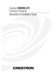
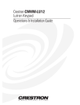
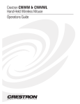
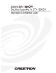
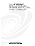
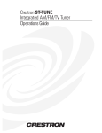
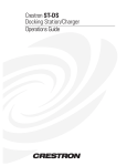
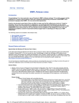
CRESTRON
Contents
Wired 8 Button Control Panel: CNWM-8
1
Description .......................................................................................................................... 1
Leading Specifications ......................................................................................................... 2
Setup.................................................................................................................................... 2
Identity Code.......................................................................................................... 2
Installation ............................................................................................................. 3
Programming with SIMPL Windows.................................................................................... 3
Problem Solving................................................................................................................... 6
Troubleshooting ..................................................................................................... 6
Further Inquiries .................................................................................................... 6
Return and Warranty Policies............................................................................................... 7
Merchandise Returns / Repair Service .................................................................... 7
CRESTRON Limited Warranty .............................................................................. 7
Operations Guide - DOC. 8130
Contents • i
CRESTRON
Wired 8 Button Control Panel:
CNWM-8
Description
The CNWM-8 wired panel, shown below, interfaces to a Crestron control system
over the CRESNET II network. The panel uses eight miniature pushbuttons with
self-contained feedback LEDs. The unit is offered in two configurations that differ
with respect to faceplate, bezel, and button cap color. The CNWM-8I is ivory and
the CNMW-8W is white. For the purposes of the Operations Guide, the term
CNWM-8 is used for either configuration. The CNWM-8 is designed for wallmounting using a single-gang eletrical box (recommended 2.5” depth). Omission of
unused buttons is standard.
NOTE: As a reference when programming, external buttons on the CNWM-8 are
numbered 1 through 8 starting from the lower right corner to the upper left corner
(when silk-screened text on rear panel is upright). Refer to button locations shown
to the right of the CNWM-8, shown below.
CNWM-8, Wired Panel
Operations Guide - DOC. 8130
Wired 8 Button Control Panel: CNWM-8 • 1
CRESTRON
Leading Specifications
The table below provides a summary of leading specifications for the CNWM-8.
Dimensions and weights are approximations rounded to the nearest hundredth unit.
Leading Specifications of the CNWM-8
SPECIFICATION
Power Requirements
Power Factor
SIMPL WindowsTM
CNX Operating System
Dimensions & Weight
DETAILS
24 VDC
5 Watts
Version 1.18 or later
Version 1.0.0 or later
Height: 4.62 in (11.74 cm)
Width: 2.86 in (7.26 cm)
Depth: 1.97 in (5.01 cm)
Weight: 0.61 lb (0.27 kg)
NOTE: Depth measurement is taken from grommet to buttons.
Setup
Identity Code
NOTE: It is safe to adjust the identity code of the CNWM-8 while the unit is
connected to the network. However, if the code is changed while the unit is
powered, the new code will not be recognized until power is removed and reapplied.
Each device on the network requires a unique identity code (NET ID). Each code
consists of a two-digit hexadecimal number from 03 to FE. The NET ID of each
unit must match the network address of the CNWM-8 in SIMPL Windows in order
for the device to be addressed properly. The NET ID of each CNWM-8 has been
factory set to 11, but may be changed. To alter the unit’s NET ID, make sure power
to the unit is disconnected and complete the following steps.
1.
2 • Wired 8 Button Control Panel: CNWM-8
Locate the two miniature rotary switches labeled HI and LO on the
rear face of the unit, shown below. The rotary switch marked HI
represents the most-significant digit or number of the ID CODE and
the one marked LO represents the least-significant digit or number of
the ID CODE. Each 16-position rotary hexadecimal switch can be set
to a value ranging between 0 and F.
Operations Guide - DOC. 8130
CRESTRON
Location of Miniature Rotary Switches
2.
Use a small screwdriver and rotate the arrow in the center of the rotary
switch marked HI to the position of the most-significant digit or letter
of the unit’s ID CODE.
3.
Use a small screwdriver and rotate the arrow in the center of the rotary
switch marked LO to the position of the least-significant digit or letter
of the unit’s ID CODE.
Installation
Complete the following steps to correctly install the CNWM-8.
NOTE: Before making any connections, review latest revision of network
interconnection drawing (Doc. 5411).
1.
Disconnect network power supply.
2.
Wire the CNWM-8 to the network wire available in the single-gang
electrical box. The wires are color coded with the color key silk
screened on the rear of the unit, shown below.
Wiring Color Key
3.
Position the unit and bezel into the electrical box and secure with two
screws.
4.
Position the faceplate over the unit with magnetic strips.
5.
Reconnect and apply network power supply.
Programming with SIMPL Windows
SIMPL Windows was designed to supersede the CRESNET II Workshop. It
provides a well-designed graphical environment with a number of workspaces (i.e.,
Operations Guide - DOC. 8130
Wired 8 Button Control Panel: CNWM-8 • 3
CRESTRON
windows) in which a programmer can select, configure, program, test, and monitor
a CRESNET control system.
NOTE: The following description assumes that the reader has some knowledge of
SIMPL Windows. If not, please refer to the extensive help information provided
with the software.
SIMPL is Crestron’s programming language designated for easy implementation of
the control system requirements. The objects that are used in SIMPL are called
symbols. A basic CNWM-8 SIMPL program is shown after this paragraph in block
diagram form. The example program toggles the button’s feedback light on and off.
Block Diagram of CNWM-8
Use the Configuration Manager workspace in SIMPL Windows to select and
configure all the devices that need to be included into the system. For this example,
add a CNWM-8 to the system and verify that its NET ID is set to 11, shown below.
NOTE: The earliest versions of SIMPL Windows did not have a “CNWM-8”
available from the Network Control Module folder in the Device Library of SIMPL
Windows’ Configuration Manager. When using an earlier version of SIMPL
Windows choose “CNMW-10A” from the Device Library instead. Since the
CNWM-10A has two more buttons, only define signal names for
PRESS/FEEDBACK (1-8). Do not assign signal names to PRESS/FEEDBACK
(9,10).
Graphical System View of CNWM-8 in SIMPL Windows’ Configuration Manager
4 • Wired 8 Button Control Panel: CNWM-8
Operations Guide - DOC. 8130
CRESTRON
Use the Programming Manager workspace in SIMPL Windows to select symbols
and assign their respective signals. Expand the Network Module folder and double
click on the CNWM-8 for a detail view (alternatively CTRL+D), shown below.
Assign the signals.
NOTE: As a reference when programming, external buttons on the CNWM-8 are
numbered 1 through 8 starting from the lower right corner to the upper left corner
(when silk-screened text on rear panel is upright).
Graphical Detail View of CNWM-8 in SIMPL Windows’ Programming Manager
For this simplified example, there are two TOGGLE symbols used, shown after this
paragraph. Each has its own unique output triggered by a specific button depression
on the CNWM-8.
Graphical Detail View of TOGGLE in SIMPL Windows’ Programming Manager
Operations Guide - DOC. 8130
Wired 8 Button Control Panel: CNWM-8 • 5
CRESTRON
Problem Solving
Troubleshooting
The table following this paragraph provides corrective action for possible trouble
situations. If further assistance is required, please contact a Crestron technical
support representative.
CNWM-8 Troubleshooting
TROUBLE
POSSIBLE CAUSE(S)
CNWM-8 does not
function when
button is
depressed.
CNWM-8 is not receiving
network power.
NET ID setting was changed
without reapplying power to
the CNWM-8.
CNWM-8 NET ID is not set to
match the NET ID of the
SIMPL program.
CNWM-8
functions, but
feedback LEDs do
not illuminate
correctly.
CNWM-8 NET ID is not
unique; two or more units
share the same NET ID.
CNWM-8 installed up-sidedown in electrical box.
CORRECTIVE ACTION
Check wiring and confirm
power is supplied to the unit.
Power down CNWM-8. Power
up to reset NET ID.
Poll network in Performance
Viewport. Verify that the CNWM8 NET ID is properly set to
match the SIMPL program.
Poll network in Performance
Viewport. Verify that each NET
ID is used once.
Verify installation; external
buttons are numbered 1
through 8 starting from the
lower right to the upper left.
Verify SIMPL program for
CNWM-8 feedback signal
names.
Further Inquiries
If after reviewing this Operations Guide for the CNWM-8, you cannot locate
specific information or have questions, please take advantage of Crestron's award
winning technical support team by calling:
•
In the US and Canada, call Crestron’s corporate headquarters at 1888- CRESTRON [1-888-273-7876] or 1-201-767-3400.
•
In Europe, call Crestron International at +32-15-50.99.50.
•
In Asia, call Crestron Asia at +852.2341.2016.
•
In Latin America, call Crestron Latin America at +525.574.15.90.
For local support from exclusive Crestron factory-trained personnel call:
•
In Australia, call Soundcorp at +613.941.61066.
•
In New Zealand, call Amber Technologies at +649.410.8382.
6 • Wired 8 Button Control Panel: CNWM-8
Operations Guide - DOC. 8130
CRESTRON
Return and Warranty Policies
Merchandise Returns / Repair Service
1.
No merchandise may be returned for credit, exchange, or service
without prior authorization from CRESTRON. To obtain warranty
service for CRESTRON products, contact the factory and request an
RMA (Return Merchandise Authorization) number. Enclose a note
specifying the nature of the problem, name and phone number of
contact person, RMA number, and return address.
2.
Products may be returned for credit, exchange or service with a
CRESTRON Return Merchandise Authorization (RMA) number.
Authorized returns must be shipped freight prepaid to CRESTRON,
Cresskill, N.J., or its authorized subsidiaries, with RMA number
clearly marked on the outside of all cartons. Shipments arriving
freight collect or without an RMA number shall be subject to refusal.
CRESTRON reserves the right in its sole and absolute discretion to
charge a 15% restocking fee, plus shipping costs, on any products
returned with an RMA.
3.
Return freight charges following repair of items under warranty shall
be paid by CRESTRON, shipping by standard ground carrier. In the
event repairs are found to be non-warranty, return freight costs shall
be paid by the purchaser.
CRESTRON Limited Warranty
CRESTRON ELECTRONICS, Inc. warrants its Cresnet II products, denoted by a
"CN" prefix model number, to be free from manufacturing defects in materials and
workmanship for a period of three (3) years from the date of shipment to purchaser.
Disk drives and any other moving or rotating mechanical parts are covered for a
period of one (1) year. CRESTRON warrants all its other products for a period of
one year from the defects mentioned above, excluding touchscreen display
components which are covered for 90 days. Incandescent lamps are completely
excluded from Crestron's Limited Warranty. CRESTRON shall, at its option, repair
or replace any product found defective without charge for parts or labor. Repaired or
replaced equipment and parts supplied under this warranty shall be covered only by
the unexpired portion of the warranty.
CRESTRON shall not be liable to honor warranty terms if the product has been
used in any application other than that for which it was intended, or if it has been
subjected to misuse, accidental damage, modification, or improper installation
procedures. Furthermore, this warranty does not cover any product that has had the
serial number altered, defaced, or removed.
This warranty shall be the sole and exclusive remedy to the purchaser. In no event
shall CRESTRON be liable for incidental or consequential damages of any kind
(property or economic damages inclusive) arising from the sale or use of this
equipment. CRESTRON makes no other warranties nor authorizes any other party
to offer any warranty, expressed or implied, including warranties of merchantability
for this product. This warranty statement supercedes all previous warranties.
Operations Guide - DOC. 8130
Wired 8 Button Control Panel: CNWM-8 • 7