1
J 280
Owner’s Guide
Workstation Systems Group
HP Part No. A2876–90013
Edition E1196
Printed in U.S.A.
Hewlett-Packard Co. 1996
First Printing:
November 1995
UNIX is a registered trademark in the United States and other countries, licensed exclusively through
X/Open Company Limited.
NOTICE
The information contained in this document is subject to change without notice.
HEWLETT-PACKARD MAKES NO WARRANTY OF ANY KIND WITH REGARD TO THIS
MATERIAL INCLUDING BUT NOT LIMITED TO THE IMPLIED WARRANTIES OF
MERCHANTABILITY AND FITNESS FOR A PARTICULAR PURPOSE. Hewlett-Packard shall
not be liable for errors contained herein or for incidental or consequential damages in connection with
the furnishing, performance or use of this material.
Hewlett-Packard assumes no responsibility for the use or reliability of its software on equipment that is
not furnished by Hewlett-Packard.
This document contains proprietary information that is protected by copyright. All rights reserved. No
part of this document may be photocopied, reproduced or translated to another language without the
prior written consent of Hewlett-Packard Company.
RESTRICTED RIGHTS LEGEND. Use, duplication, or disclosure by government is subject to
restrictions as set forth in subdivision (c) (1) (ii) of the Rights in Technical Data and Computer Software
Clause at DFARS 252.227.7013. Hewlett-Packard Co., 3000 Hanover St., Palo Alto, CA 94304.
10 9 8 7 6 5 4 3 2 1
xii
Table of Contents
System Overview ................................................................................
1-1
Product Description ...........................................................................................
System Unit Front Panel Controls, LED, and LCD ............................................
1-3
1-6
System LCD ........................................................................................................................
System Power Switch ..........................................................................................................
System Power LED .............................................................................................................
Removable Device Buttons and LEDs ................................................................................
1-7
1-7
1-8
1-8
System Unit Rear Panel Connectors .................................................................
1-10
Audio Connectors ................................................................................................................
Keyboard Connectors ..........................................................................................................
HP Parallel I/O Connector ...................................................................................................
Network Connectors ............................................................................................................
RS-232C Serial Input/Output Connector .............................................................................
SCSI Connectors .................................................................................................................
Power Cord Connector ........................................................................................................
1-12
1-14
1-15
1-15
1-15
1-16
1-16
Monitors .............................................................................................................
Pointing Devices ................................................................................................
Operating System Overview ..............................................................................
Important Information You Need to Note ...........................................................
1-17
1-18
1-19
1-20
LANIC ID .............................................................................................................................
IP Address and Subnetwork Mask Information ...................................................................
1-20
1-21
Networking Overview ........................................................................................
1-22
Mail ......................................................................................................................................
telnet ....................................................................................................................................
rlogin ....................................................................................................................................
ftp .........................................................................................................................................
rcp........................................................................................................................................
NFS .....................................................................................................................................
1-22
1-22
1-22
1-23
1-23
1-23
Using Your CD-ROM Drive .................................................................
2-1
CD-ROM Drive and CD- ROM Media Descrip-tions ..........................................
2-3
CD-ROM Drive ....................................................................................................................
CD-ROM Media ...................................................................................................................
2-3
2-5
Operating the CD- ROM Drive ..........................................................................
2-6
Loading and Unloading a CD-ROM Disc .............................................................................
Verifying the CD-ROM Drive Operation ...............................................................................
Using Device Files ...............................................................................................................
2-6
2-11
2-14
Mounting and Unmounting a CD- ROM Disc ....................................................
2-15
Mounting a CD-ROM Disc Using SAM ................................................................................
Unmounting a CD-ROM Disc Using SAM ...........................................................................
Reading the Busy Light .......................................................................................................
Troubleshooting ...................................................................................................................
2-15
2-17
2-19
2-20
Using Your DDS Tape Drive ..............................................................
3-1
DDS Tape Drive and Data Cassette Descriptions .............................................
3-3
DDS Drive ............................................................................................................................
Data Cassettes ....................................................................................................................
Setting the Write-Protect Tab on a Data Cassette ..............................................................
3-3
3-7
3-8
Operating the DDS Tape Drive .........................................................................
3-9
Loading and Unloading a Data Cassette .............................................................................
3-9
Verifying the DDS Tape Drive Operation.............................................................................
Using Device Files ...............................................................................................................
Determining Available Device Files .....................................................................................
Archiving Data in Compressed and Noncompressed Mode ................................................
Writing to a Data Cassette...................................................................................................
Restoring Files from a Data Cassette to Your System ........................................................
Listing the Files on a Data Cassette ....................................................................................
Further Command Information ............................................................................................
Media Interchangeability Restrictions ..................................................................................
Troubleshooting ...................................................................................................................
Ordering Information............................................................................................................
3-10
3-12
3-12
3-14
3-15
3-15
3-17
3-18
3-18
3-18
3-19
Using Your 3.5-Inch Floppy Disk Drive ............................................
4-1
Using the Floppy Diskette .................................................................................
4-3
Setting the Write-Protect Tab on a Diskette ........................................................................
Inserting and Removing a Diskette......................................................................................
4-3
4-4
Operating the Floppy Drive ...............................................................................
4-5
Verifying the Floppy Drive Configuration .............................................................................
Using Device Files ...............................................................................................................
Formatting a New Diskette ..................................................................................................
Transferring Data To and From a Floppy Diskette ..............................................................
Saving Files to a Floppy Diskette ........................................................................................
Restoring Files from a Floppy Diskette to Your System ......................................................
Listing the Files on a Floppy Diskette ..................................................................................
For More Information ...........................................................................................................
Configuring the Floppy Driver ..............................................................................................
Troubleshooting ...................................................................................................................
Ordering Information............................................................................................................
4-5
4-6
4-8
4-8
4-9
4-9
4-10
4-10
4-12
4-12
4-12
Solving Problems ...............................................................................
5-1
Common Problems and Solutions .....................................................................
Dealing with a Boot Failure ...............................................................................
Memory Failures ................................................................................................
LCD-Indicated Problems ...................................................................................
Running System Verification Tests ...................................................................
5-3
5-10
5-11
5-12
5-15
Safety and Regulatory Statements ...................................................
A-1
Emissions ..........................................................................................................
A-3
Federal Communications Commission (FCC) .....................................................................
A-3
Regulations .......................................................................................................
A-3
VCCI Class 1 ITE ................................................................................................................
A-4
Emissions Regulations Compliance ..................................................................
Datacom Users Statement ................................................................................
A-4
A-4
(United .................................................................................................................................
Kingdom Only) .....................................................................................................................
A-4
A-4
Acoustics ...........................................................................................................
A-4
Regulation On Noise Declaration For Machines 3. GSGV .................................................
A-4
Electrostatic Discharge (ESD) Precautions .......................................................
Laser Safety Statement (For U. S. A. Only) ......................................................
IEC 825 Class 1 Laser Label .............................................................................
Warnings and Cautions .....................................................................................
A-4
A-5
A-5
A-6
Changing Your Workstation s Hardware Configuration .................
B-1
Checking the SCSI IDs ......................................................................................
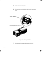
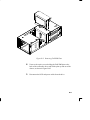
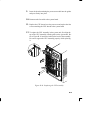
Opening the System Unit ..................................................................................
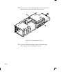
Closing the System Unit ....................................................................................
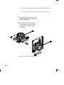
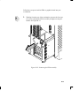
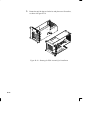
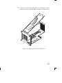
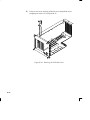
Installing Removable Media Devices ................................................................
B-3
B-6
B-8
B-10
CD-ROM Drive ....................................................................................................................
DDS Tape Drive ..................................................................................................................
Floppy Drive ........................................................................................................................
B-15
B-17
B-21
Adding a Hard Drive ..........................................................................................
B-28
Installing a Hard Disk Drive .................................................................................................
Configuring a Hard Drive .....................................................................................................
B-31
B-34
Installing Additional Memory .............................................................................
Replacing the ....................................................................................................
Processor ..........................................................................................................
Module 1. ...........................................................................................................
Installing an EISA or Graphics Board ................................................................
Changing Your Monitor Type ............................................................................
B-37
B-45
B-45
B-45
B-51
B-61
Setting the Monitor Type from the Boot Console Interface..................................................
Setting the Monitor Type at Power On ................................................................................
B-61
B-61
SCSI Connections ..............................................................................
C-1
SCSI Bus Differences ........................................................................................
SCSI Restrictions ..............................................................................................
C-3
C-5
Cables .................................................................................................................................
Connectors and Terminator .................................................................................................
SCSI Configuration Constraints ...........................................................................................
C-5
C-7
C-7
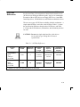
Determining SCSI Bus Length ..........................................................................
C-9
Single-Ended SCSI-2 Bus Length .......................................................................................
Fast, Wide SCSI-3 Bus Length ............................................................................................
C-9
C-12
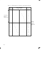
Assigning SCSI Device IDs ...............................................................................
C-14
Single-Ended Standard System SCSI Device IDs...............................................................
Fast, Wide SCSI IDs ............................................................................................................
C-16
C-20
Connecting to the SCSI Ports ...........................................................................
C-21
System SCSI Port Connection ............................................................................................
C-21
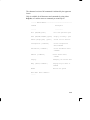
The Boot Console Interface ...............................................................
D-1
Boot Console Interface Features .......................................................................
Accessing the Boot Console Interface ..............................................................
Booting Your Workstation ..................................................................................
Searching for Bootable Media ...........................................................................
Resetting Your Workstation ...............................................................................
Displaying and Setting Paths ............................................................................
Displaying and Setting the Monitor Type ...........................................................
D-2
D-7
D-9
D-12
D-13
D-14
D-16
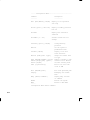
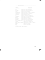
The Monitor Command ........................................................................................................
D-16
Displaying the Current Monitor Configuration ...................................................
D-18
Setting the Monitor Type .....................................................................................................
D-19
Setting the Monitor Type at Power On ..............................................................
D-22
Displaying the Current Memory Configuration ..................................................
Displaying the Status of the System I/O ............................................................
Setting the Auto Boot and Auto Search Flags ...................................................
Displaying and Setting the Security Mode .........................................................
Displaying and Setting the Fastboot Mode ........................................................
Displaying the LAN Station Address .................................................................
Displaying System Information ..........................................................................
Displaying PIM Information ...............................................................................
D-24
D-29
D-31
D-33
D-34
D-35
D-35
D-36
Preface
xiii
This owner’s guide describes how to use your HP 9000 J280 workstation.
This manual assumes that you have installed your workstation as
described in the J Class Hardware Installation Guide.
xiv
Audience
This guide is intended for HP 9000 J280 workstation users.
Safety and
Regulatory
Statements
See Appendix A in the back of this manual for safety and regulatory
statements that apply to this workstation.
Release
Document(s)
Please refer to the Release Document(s) you received with your system or system software for additional information that we may not
have been able to include in this guide at the time of its publication.
xv
If you are using HP-UX version 10.20, refer to the following manuals
for more information:
•
J Class Hardware Installation Guide (A2876–90010)
•
Using Your HP Workstation (A2615–90003)
•
Installing and Updating HP-UX (B2355–90050)
•
•
•
•
System Administration Tasks HP 9000 Series 700 Computers
(B2355–90051)
Configuring HP-UX for Peripherals
(B2355–90053)
HP Visual User Environment User’s Guide (B1171–90079)
Managing Clusters of HP 9000 Computers: Sharing the HP-UX
File System (B2355–90038)
To order manuals, please contact your local sales office.
Revision History
xvi
The revision history for each edition of the manual is listed below:
HP Part No.
Edition
Revision History
A4081–90601
A4081–90607
A4476–90013
E0195
E0695
E0596
First printing
Second printing
Third printing
A2876–90013
E0996
Latest printing
Documentation
Conventions
Unless otherwise noted in the text, this guide uses the following symbolic conventions.
literal values
Bold words or characters in formats and command descriptions represent commands or key words that you
must use literally. Pathnames are also in bold.
user-supplied
values
Italic words or characters in formats and command
descriptions represent values that you must supply.
sample user
input
In examples, information that the user enters appears
in color.
output
Information that the system displays appears in
this typeface.
Enter
Screen Button
A colored rectangle with rounded corners and a key
label denotes a key on your keyboard. (In this manual
we refer to the Enter key. On your keyboard the key
may be labeled either Enter or Return.)
This colored symbol with a label in it denotes an HP
VUE screen button. A screen button is a key or button
which is drawn on your workstation’s graphic display
by HP VUE. It works like a keyboard key, except that
you must move the mouse cursor over it and press the
left mouse button to activate it. The screen button’s label describes its function.
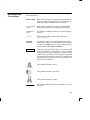
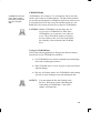
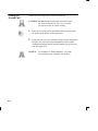
This symbol indicates a notice.
This symbol indicates a procedure.
This symbol indicates a caution.
This symbol indicates the end of a chapter or a part of
this guide.
xvii
Questions,
Suggestions, or
Problems
xviii
If you have any questions, suggestions, or problems with our hardware, software, or documentation, please call 1–888–301–5932 (US
& Canada) or contact the HP Response Center for your country.
Chapter 1
System Overview
•
Product description
•
System unit front panel controls, LED, and LCD
•
System unit rear panel connectors
•
Monitors
•
Keyboard and Mouse
•
Pointing devices
•
Operating system overview
•
Important information you need to note
•
Networking overview
1-1
This chapter introduces the HP 9000 J 280 workstation. Its purpose is
to familiarize you with your workstation and its controls and indicators.
The instructions in this chapter assume you are using the HP-UX
version 10.20 or later operating system with the HP VUE version 3.0
interface.
1-2
Product
Description
This workstation has the following key features:
•
Operating System
HP-UX version 10.20 or later
•
User Interface
HP VUE version 3.0 graphical user
interface or HP CDE
•
Compatibility
Source and binary code compatible
with the Series 700 product family
•
Monitors
17-inch 1280x1024 color monitor
or
20-inch 1280x1024 color monitor
•
Optional Graphics
HP VISUALIZE–EG, 8–plane 2D
graphics
HP VISULAIZE–48XP, 48–plane
graphics
HP VISUALIZE–8/24, Accelerated
8–plane or 24–plane 3D graphics
•
Main Memory
32 MB to 2 GB
•
Internal Storage Devices
•
Standard Network
Fast, wide SCSI hard disk drives
up to two:
2.0 GB Drive
4.0 GB Drive
Single-Ended SCSI removable
Media – up to two:
CD-ROM Drive
2.0–8.0 GB, 4-mm DDS tape
drive
Floppy drive (not a SCSI Device)
Ethernet IEEE 802.3 AUI Thicknet
or
RJ45, UTP Twisted Pair
1-3
•
1-4
Standard I/O
One SCSI-2: Single-Ended,
8-bit (for removable devices)
5 MB/sec synchronous
1.5 MB/sec asynchronous
ALT-1, 50-pin, high density
SCSI-2 connector
One SCSI-3: Fast, wide (for hard disk
drives)
20 MB/sec synchronous
68-pin, high-density SCSI-3
P connector
Two serial interfaces
RS-232C, 9-pin male
One parallel interface
Centronics, BUSY handshake
25-pin female
•
EISA/GSC
Five slots total; four EISA and
three GSC that can be used as
follows: two individual EISA, one
individual GSC, and two
combination EISA or GSC.
•
Keyboard
PS/2 Keyboard
•
Mouse
PS/2 Mouse
1-5
System Unit
Front Panel
Controls, LED,
and LCD
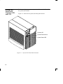
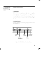
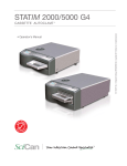
Before powering on your system, you should become familiar with
the system unit controls.
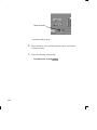
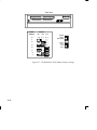
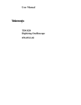
Figure 1–1 shows the the system unit front panel controls.
Figure 1–1. System Unit Front Panel Controls
1-6
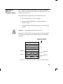
System LCD
The Liquid Crystal Display (LCD) is located on the left side of the
front panel. It displays messages about the state of the system, including error codes. The following symbols appear in the LCD, representing the different system activities shown:
Operating system running
Disk Access in progress
Network Receive in progress
Network Transmit in progress
Figure 1–2. LCD Symbols
System Power Switch
Use the Power switch to power the system unit on and off.
CAUTION: Do not turn off the power to your workstation
without first performing the recommended
shutdown procedure. If you do not shut down
your workstation properly, you can damage the
programs and data on your disk.
Using the proper shutdown method for your
workstation and operating system also ensures
that your system produces the proper diagnostic
and self test messages, and broadcasts a warning message to remote terminals that it is about
to shutdown.
1-7
Follow the instructions in Using Your HP Workstation to shut down
your workstation.
System Power LED
The Power Light Emitting Diode (LED) is located on the left side of
the front panel. It lights when the system unit power is on and flashes
until the OS is booted. Once the OS is booted, the LED remains on
without flashing.
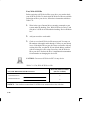
Removable Device Buttons and LEDs
Depending on your configuration, you can have up to two (2) of the
following removable device drives:
•
CD-ROM disc drive
•
DDS tape drive
•
Floppy diskette drive
NOTICE:
You cannot have two of the same type of device. For example, you can have a CD-ROM
device and a floppy device, but not two CDROMs.
A description of each drive’s controls and indicators is in the chapter
describing that device, later in this book.
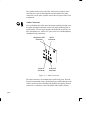
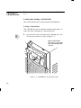
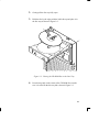
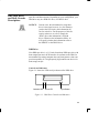
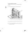
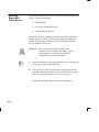
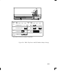
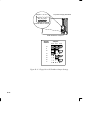
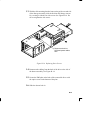
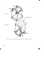
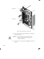
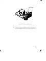
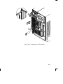
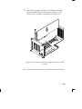
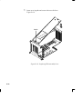
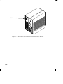
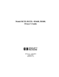
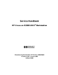
Figure 1–3 shows the system unit with the removable device door
open. A removable device is in the top bay; a blank covers the empty
bottom bay.
1-8
Removable Device
Bays (2)
Figure 1–3. System Unit with Removable Device Door Open
1-9
System Unit
Rear Panel
Connectors
This section describes the following connectors on the system unit’s
rear panel:
•
Audio connectors (including headphones and microphone)
•
PS/2 keyboard and mouse connectors
•
HP parallel Centronics I/O connector
•
802.3 AUI LAN connector
•
802.3 TP (Twisted Pair) LAN connector
•
RS-232C serial I/O connectors
•
SCSI connectors (including fast, wide SCSI-3 and
single-ended SCSI-2
•
TOC button
•
Power cord connector
NOTICE:
To maintain FCC/EMI compliance, verify that
all cables are fully seated and properly fastened.
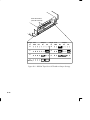
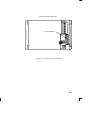
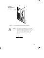
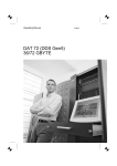
Figure 1–4 shows the locations of the connectors on the system unit’s
rear panel.
1-10
Audio
Connectors**
Fast, Wide SCSIĆ3
Connector*
SingledĆEnded
SCSIĆ2 Connector*
TOC
Button
(not shown)
Mouse
Connector
Keyboard
Connector
Parallel I/O
Connector
AUI LAN
Connector
Twisted Pair
Connector
(labeled UTP)
RSĆ232C
Connectors
*SCSI Connectors are
shown with terminators
attached, as they are
shipped from the factory.
**See Figure 1-5 for detail
on Audio Connectors.
Power
Connector
Graphics
Connector
Figure 1–4. System Unit Rear Panel Connectors
1-11
The symbols shown to the left of the connector descriptions in the
following text, such as the headphone and microphone for audio
connectors, are the same symbols used on the rear panel of the J 280
workstation.
Audio Connectors
Your workstation has audio input and output capability through external input and output connectors on the rear panel and through an internal speaker. The rear panel contains the Audio IN (stereo line-in),
Mic (microphone-in), Audio OUT (stereo line-out), and Headphones
(headphones-out) connectors.
Headphones OUT
Connector
Audio IN
Connector
Mic IN
Connector
Audio OUT
Connector
Figure 1–5. Audio Connectors
The audio connectors are standard stereo audio mini-jacks. HewlettPackard recommends using gold-plated plugs available through audio
retailers for best quality recording and playback through the external
connectors. A summary of the workstation audio features follows.
1-12
•
Audio Features
Programmable sample rates:
8kHz, 16kHz, 32kHz, 48kHz, 11.025kHz,
22.05kHz, and 44.1kHz.
Programmable output attenuation:
0 to –96dB in –1.5dB steps
Programmable input gain:
0 to 22.5dB in 1.5dB steps
Input monitoring:
16-bit linear, 8-bit u-law, or A-law
coding
•
Audio Inputs
Line-in
Mono microphone compatible with
1.5V phantom supply (bias voltage
supplied by the system)
CD-ROM audio (if internal CD–ROM is
installed)
•
Audio Outputs
Line-out
Headphone
Mono speaker jacks
Built-in mono speaker
•
Audio CODEC
Crystal CS4215
1-13
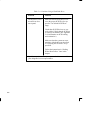
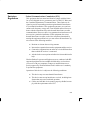
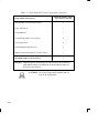
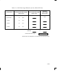
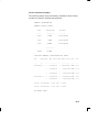
Table 1–1 summarizes the audio electrical specifications for this workstation.
Table 1–1. Audio Electrical Specifications
Frequency Response
Input Sensitivity/Impedance
Line in
Microphone
25–20,000Hz
2.0Vpk/47kohm
22mVpk/1kohm
Max Output Level/Impedance
Line Out
Headphone
Speaker (internal)
2.8Vpp/47kohm
2.75Vpp/50ohm
5.88Vpp/48ohm
Output Impedance
Line Out
Headphone
619ohm
118ohm
Signal to Noise Line Out
Headphone
Speaker
Line In
Microphone
THD (w/nominal load)
Line Out
Headphone
Speaker
Line In
Microphone
65dB
61dB
63dB
61dB
57dB
–73dB
–70dB
–68dB
–75dB
–73dB
~
To convert from dB to number of significant bits, use the formula:
dB .
n = dB
20 log
6
For example, for 61dB S/N then n= 61/6 10
10
significant bits, or in other words, about 6 bits of noise.
Keyboard Connectors
PS/2 Keyboard Connectors
The PS/2 connectors provide an interface for the keyboard and mouse
to the system. Consult the documentation that accompanies each input
device for specific information concerning its use.
1-14
HP Parallel I/O Connector
The 25-pin HP Parallel I/O interface uses Centronics interface protocols to support peripheral devices such as printers and plotters. Consult the documentation that accompanies each peripheral device for
specific information concerning its use.
802.3 Network Connectors
Your workstation has built-in ThickNet LAN AUI and TP (Twisted
Pair) connectors for the 802.3 (ETHERNET) network. Connections to
ThinLAN networks require an external transceiver. Your workstation
will automatically select the correct network setting.
RS-232C Serial Input/Output Connector
You can attach a variety of pointing devices (such as a mouse or
trackball), or peripheral devices to the RS-232C Serial Input/Output
(SIO) ports on the J280 workstation. Peripheral devices include printers, plotters, modems, and scanners. Consult the documentation that
accompanies each pointing or peripheral device for specific information concerning its use.
The SIO ports are programmable. You can set functions such as bit
rate, character length, parity, and stop bits. The SIO Ports are used as
an interface for serial asynchronous devices to the CPU. The ports
operate at up to a 19.2 K baud rate.
Table 1–2 shows the SIO connector pin listings. The serial connectors
are 9-pin D-sub connectors. Signal names are those specified in the
EIA RS-232 standard.
1-15
Table 1–2. Serial I/O Pins
Pin No.
Signal
Description
1
2
3
4
5
6
7
8
9
DCD
RXD
TXD
DTR
GND
DSR
RTS
CTS
RI
Data Carrier Detect
Receive Data
Transmit Data
Data Terminal Ready
Ground
Data Set Ready
Request To Send
Clear To Send
Ring Indicator
SCSI Connectors
Use the SCSI connectors to connect external SCSI devices such as
DDS-format tape drives and CD-ROM drives. Consult the documentation that accompanies each SCSI device for specific information
concerning its use. Refer to Appendix C for information about connecting SCSI devices to your workstation.
NOTICE:
When attaching external SCSI devices, be sure to
terminate the last device on the external SCSI bus.
Power Cord Connector
Plug the workstation’s power cord into the power cord connector to
provide ac power to the system.
1-16
Monitors
You can use one of the following HP monitors with your workstation:
•
17-inch, 1280x1024 color monitor (A4032A)
•
17-inch, 1280x1024 color monitor (A4330A)
•
20-inch, 1280x1024 color monitor (A4033A)
•
20–inch, 1280x1024 color monitor (A4331A)
Before using your monitor, you should become familiar with its controls, connectors, and indicators. For information on these controls
and indicators and on using your monitor, see the documentation that
came with it.
1-17
Pointing Devices
You can use an HP three-button mouse (PS/2), a trackball, or other
options as pointing devices with your workstation by using the serial
ports. For instructions on using your particular pointing device, see
the manual that came with it.
For general information on using three-button mice and on the various cursor shapes associated with different areas of HP VUE while
using a mouse, see Using Your HP Workstation.
1-18
Operating
System
Overview
Your workstation uses the HP-UX operating system, 10.20 or later.
Instant Ignition systems, (systems with preloaded software), have Xwindows and Hewlett-Packard’s graphical user interface, HP VUE
version 3.0, or HP CDE installed and configured.
Please refer to the “Instant Ignition System Configuration Information” sheet that shipped with your system for details on configuration.
If your Instant Ignition system does not have the kernel preconfigured
with all of the device drivers you need, refer to the manual System
Administration Tasks HP 9000 Series 700 Computers to reconfigure
your kernel.
If you have any questions about Instant Ignition, refer to Using Your
HP Workstation for more information.
1-19
Important
Information
You Need to
Note
Before you begin using your workstation, take a moment to gather the
following important information and note it in the appropriate subsection for future use:
•
LANIC ID
•
Internet Protocol (IP) address
•
Subnetwork mask
NOTICE:
For help with these, refer to Using your HP
Workstation.
LANIC ID
Locate the contents label that comes with the workstation shipping
carton. Find the LANIC ID listed there and record it here:
LANIC ID _______________________________________________
You can also get your LANIC ID by using the the lanscan command
in a terminal window.
1-20
IP Address and Subnetwork Mask Information
Get the IP address and the subnet mask information for your workstation from either your system administrator or your network administrator and note them here:
IP address ______________________________________________
subnet mask _____________________________________________
1-21
Networking
Overview
Your workstation is capable of many more tasks than are described in
this owner’s guide. This section gives an overview of some of the networking capabilities of your system and directs you to the appropriate
source for more information.
Mail
Electronic mail allows you to send and receive mail messages on your
workstation. For information on setting up and using electronic mail
on your workstation, contact your system administrator and also see
the Using Your HP Workstation manual that came with your workstation.
telnet
The telnet application uses the TELNET protocol to communicate
with another computer system on the network. The telnet application
allows you to log on to the remote system from your workstation. For
more information on telnet read the online man page by entering the
following at a command-line prompt:
man telnet
Enter
rlogin
The rlogin application also allows you to log on to another computer
system on the network from your workstation. For more information
on rlogin see the Using Your HP Workstation manual that came with
your workstation and read the online man page by entering the following at a command-line prompt:
man rlogin
1-22
Enter
ftp
The ftp application is a user interface to the File Transfer Protocol.
Use ftp to copy files between your workstation and another computer
system on the network. For more information see the Using Your HP
Workstation manual that came with your workstation and read the
online man page by entering the following at a command-line prompt:
man ftp
Enter
rcp
The rcp application allows you to remotely copy files from another
computer system on a network to your workstation. For more information see the Using Your HP Workstation manual that came with
your workstation and read the online man page by entering the following at a command-line prompt:
man rcp
Enter
NFS
The Network File System (NFS) allows your workstation to access
files on remote computer systems as if they were on your local system. The file system on the remote computer system does not have to
be compatible with your workstation’s file system. For more information see Installing and Administering NFS Servers and HP-UX System
Administration Tasks manuals.
1-23
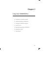
Chapter 2
Using Your CD-ROM Drive
•
CD-ROM drive and media descriptions
•
Loading and unloading a CD-ROM disc
•
Verifying the CD-ROM drive operation
•
Using device files
•
Mounting and unmounting a CD-ROM disc
•
Reading the busy light
•
Troubleshooting
2-1
This chapter provides an overview of the optional CD-ROM drive
and media, and describes how to use the CD-ROM drive. We assume
the CD-ROM drive is set to the factory default address of SCSI ID 2.
The instructions in this chapter assume you are using the HP-UX
version 10.20 or later operating system with the HP VUE version 3.0
interface.
2-2
NOTICE:
Be sure you have read and understand the
information on mounting and unmounting
CD-ROM discs before you begin using your
CD-ROM disc drive.
NOTICE:
Some procedures in this chapter require you to
log in as root. If you cannot log in as root, contact your system administrator.
CD-ROM Drive
and CD-ROM
Media Descriptions
This section describes basic information needed for using the CDROM drive and CD-ROM discs.
CD-ROM Drive
The CD-ROM drive is a random access read-only mass storage device that uses removable CD-ROM discs. The drive supports the ISO
9660 and High Sierra format standards. You can access information
from the drive like any other disk drive, except that you cannot write
to the drive. The drive contains a semiconductor laser for reading data
optically, and includes an embedded controller with a SCSI interface.
Controls and Features
Figure 2–1 and Table 2–1 describe the operating controls and features
of the CD-ROM drive.
Headphone
Jack
Volume
Control
Thumbwheel
Busy
Indicator
Emergency
Eject Hole
Eject
Button
Figure 2–1. CD-ROM Drive Controls and Features
2-3
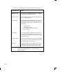
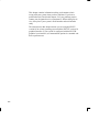
Table 2–1. CD-ROM Drive Operating Controls and Features
Headphone Jack
You can plug mini-headphones with a 3.5 mm diameter miniature stereo plug into this jack.
Volume Control
Use the volume control to adjust the audio output volume to the headphone jack.
Busy Indicator
The Busy Indicator lights during a data access operation and blinks during a data transfer. The indicator
blinks initially and then stays lit when there is one of
the following:
A defective disc
A disc insertion error
(for example, an upside-down disc)
No disc present
Eject Button
Press the Eject Button to open the Disc Tray and insert or remove a disc. When the drive is in use, you
must press the eject button for more than one second
to open the Disc Tray.
Emergency Eject
By removing the Phillips type screw and inserting the
end of a paper clip, you can open the Disc Tray when
the workstation does not have power.
Disc Tray
The disc tray holds the CD-ROM disc. This style of
CD-ROM drive does not use a disc caddy. The disc
tray does not open if the workstation power is off.
NOTICE:
2-4
The Volume Control, Headphone Jack, and Audio Jack
features of the CD-ROM drive are supported through
applications only.
CD-ROM Media
CD-ROM discs are identical to audio compact
discs (CDs), except that
they store computer
data.
CD-ROM discs are 120 mm (4.7 in.) in diameter, and use one data
surface with a capacity of 600 megabytes. The data surface contains
pits and flat spots arranged in a continuous spiral track, which is read
at a constant speed. You may access files and data stored on a CDROM disc, but you may not write files or data to a CD-ROM disc.
CAUTION: Handle CD-ROM discs by the edges only. Always be sure a CD-ROM disc is either in the
CD-ROM drive or its protective case when not
in use. This will lessen the chance of exposing
the disc surface to dust. Over time, dust reduces
the reliability of the read head in the CD-ROM
drive.
Caring for CD-ROM Discs
Observe the following guidelines to help prevent data loss and prolong the life of your CD-ROM discs and drive:
•
•
•
Use CD-ROM discs in a clean environment to prevent dust particles from scratching disc surfaces.
Store CD-ROM discs in a cool, dry place to prevent moisture
and heat damage.
Don’t try to clean the surface of a CD-ROM disc with cleaning
solvents, as some cleaning solvents may damage the disc.
NOTICE:
You must mount the disc after loading it into
the drive. Refer to the section “Mounting and
Unmounting a CD-ROM Disc,” later in this
chapter, for instructions.
2-5
Operating the
CD-ROM Drive
This section describes how to perform tasks with your CD-ROM
drive.
Loading and Unloading a CD-ROM Disc
This section describes how to load or unload a CD-ROM disc.
Loading a CD-ROM Disc
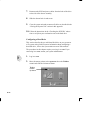
This CD-ROM drive has an automatic loading/ejecting feature. To
load a disc in the CD-ROM drive, follow these steps:
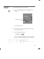
1.
Press and release the eject button on the CD-ROM drive. The
disc tray opens partway, as shown in Figure 2–2.
Figure 2–2. CD-ROM Disc Tray Partway Open
2-6
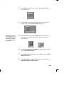
2.
Gently pull the disc tray fully open.
3.
Hold the disc by the edges with the label side up and place it in
the disc tray as shown in Figure 2–3.
Figure 2–3. Placing the CD-ROM Disc in the Disc Tray
4.
Press down gently on the center of the CD-ROM disc to make
sure it is seated on the disc tray hub, shown in Figure 2–3.
2-7
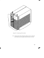
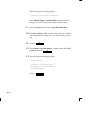
5.
Gently push the disc tray in until it is closed, as shown in
Figure 2–4.
Figure 2–4. Disc Tray Closed
2-8
Unloading a CD-ROM Disc
To unload a disc from the Disc Tray, follow these steps:
1.
Press and release the eject button on the CD-ROM drive. The
disc tray opens approximately 1 inch, as shown in Figure 2–5.
Figure 2–5. CD-ROM Disc Tray Partway Open
2.
Gently pull the disc tray fully open.
2-9
3.
Grasp the disc by the edges and lift it out of the disc tray, as
shown in Figure 2–6. Be careful to touch only the edges of the
disc.
Figure 2–6. Removing the CD-ROM Disc From the Disc Tray
2-10
4.
Gently push the disc tray in until it is closed, as shown in
Figure 2–7.
Figure 2–7. Disc Tray Closed
Verifying the CD-ROM Drive Operation
The ioscan utility verifies
the configuration of all
drives.
To verify that your workstation can communicate with the CD-ROM
drive, follow these steps:
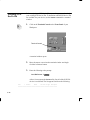
1.
Click on the Terminal Control on the Front Panel of your
Workspace.
2-11
Terminal Control
A terminal window opens.
2.
Move the mouse cursor into the terminal window and click the
left mouse button.
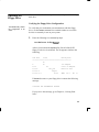
3.
Enter the following at the prompt:
/usr/sbin/ioscan –d sdisk
2-12
Enter
.
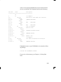
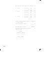
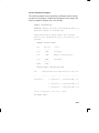
After a few moments the ioscan utility lists all of the SCSI I/O
devices it could find. The list appears similar to the following:
H/W Path
Class
Description
============================================
bc
8
bc
I/O Adapter
8/0
ext_bus
GSC built-in Fast/Wide SCSI Interface
8/0.0
target
8/0.0.0
disk
QUANTUM LPS1080WD
8/0.5
target
8/0.5.0
disk
DEC
DSP3210SW
8/0.6
target
8/0.6.0
disk
DEC
DSP3210SW
8/12
ba
Core I/O Adapter
8/12/5
ext_bus
Built-in SCSI
8/12/5.2
target
8/12/5.2.0
disk
TOSHIBA CD-ROM XM-4101TA
8/12/5.4
target
8/12/5.4.0
disk
SEAGATE ST3600N
8/12/5.6
target
8/12/5.6.0
disk
MICROP 2112
10
bc
I/O Adapter
10/12
ext_bus
GSC add-on Fast/Wide SCSI Interface
10/12.4
target
10/12.4.0
disk
SEAGATE ST31200W
If ioscan does not see your CD-ROM drive it returns the following message:
ioscan: No hardware found
If you receive this message, go to Chapter 6, “Solving Problems.”
2-13
Using Device Files
Device files are special files that tell your system which pathway to
use through the system hardware when communicating with a specific
device and what kind of device it is.
To determine what device files are available for use with your CD–
ROM drive, use the following procedure:
NOTICE:
1.
In a terminal window, enter the following command:
sam
2-14
The device file names will depend on the naming conventions of your particular system. See
“SCSI ID and Device File Information for HPUX 10.20 or Later” in Chapter 1 of this book.
Enter
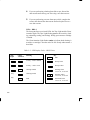
2.
The System Administration Manager (SAM) window opens.
Double–click on Peripheral Devices –>.
3.
The Peripheral Devices window opens. Double–click on CD–
ROM Drives –>.
4.
The CD–ROM Drives window opens.
5.
In the list of CD–ROM drives, click on the desired CD–ROM
drive to select it.
6.
From the Actions menu, click on Show Device Files.
A window opens with a list of the device files for the selected
CD–ROM drive with an explanation of each one.
Mounting and
Unmounting a
CD-ROM Disc
To access information on a CD-ROM disc, you must first mount the
disc. This applies to file system information only. If you wish to load
a music CD, for example, you would not need to mount the disc.
Mounting a disc with file system information on it gives the disc a
pathname that allows your workstation to communicate electronically
with it. You must unmount the CD-ROM disc before removing it
from the drive.
CAUTION: To use a CD-ROM disc as a mounted file system, you must mount the CD-ROM disc every
time you load it into the drive. You must also
unmount the CD-ROM disc every time you
unload it from the drive. Failure to mount or
unmount a disc can cause a system error condition and can also require rebooting the system.
The procedures in this chapter require you to log in as root. If you
cannot log in as root, contact your system administrator.
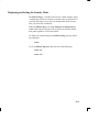
SAM (System Administration Manager) is a utility that performs system
administration tasks using a windows graphical
user interface.
Mounting a CD-ROM Disc Using SAM
Use the following procedure to mount a CD-ROM disc:
1.
Log in as root. If you need information on logging in or setting
up a user account, see Using Your HP Workstation.
2.
Load the CD-ROM disc into the disc tray and gently push the
tray into the drive.
3.
In a terminal window, enter the following command:
sam
4.
Enter
The System Administration Manager window opens. Double–
click on Peripheral Devices–>.
2-15
5.
The Peripheral Devices window opens. Double–click on Disks
and File Systems–>.
6.
The Disks and File Systems window opens. Double–click on
CD–ROM, Floppy, and Hard Disks.
The following screen message appears:
Scanning the system’s hardware...
The CD–ROM, Floppy, and Hard Disks window opens containing a list of drives currently configured on thie system.
Disks that are unmounted have the word ”unused” in the Use
column.
7.
From the Actions menu, click on Add a Hard Disk Drive.
8.
The Select a Disk to Add... window opens with a list of unused
disks. Highlight the CD-ROM disc you want to mount.
9.
Click on
OK
.
10. The Set Disk Usage and Options... window opens. Select File
System and click on
11.
OK
.
The following screen messages appear:
Task started.
Creating the device file...
Mounting file system...
Modifying “/etc/checklist”...
Task completed.
2-16
Click on
OK
.
Now you can access the CD-ROM disc as you would any other
mounted file system.
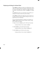
Unmounting a CD-ROM Disc Using SAM
Use the following procedure to unmount a CD-ROM disc:
NOTICE:
Before you unmount a CD-ROM disc, make
sure that your working directory (the directory
in which a relative path name search begins) is
set to some directory other than the one under
which the disc was mounted.
CAUTION: If you wish to use a CD-ROM disc as a
mounted file system, you must mount the CDROM disc every time you load it into the drive.
You must also unmount the CD-ROM disc
every time you unload it from the drive. Failure
to mount or unmount a disc may cause a system
error condition and may also require rebooting
the system.
1.
Log in as root. If you need information on logging in or setting
up a user account, see Using Your HP Workstation.
2.
In a terminal window, enter the following command:
sam
Enter
3.
The System Administration Manager window opens. Doubleclick on Peripheral Devices –>.
4.
The Peripheral Devices window opens. Double-click on Disks
and File Systems –>.
2-17
5.
The Disks and File Systems window opens. Double-click on
CD-ROM, Floppy, and Hard Disks.
The following screen message appears:
Scanning the system’s hardware...
The CD-ROM, Floppy, and Hard Disks window opens containing a list of drives currently configured on this system.
6.
Highlight the disc you want to unmount and click on Remove a
Hard Disk Drive from the Actions menu.
7.
A window with the following message opens:
Do you want to remove the disk?
Click on
8.
2-18
Yes
. The system reboots.
Press the eject button on the CD-ROM drive and remove the
CD-ROM disc from the disc tray.
Reading the Busy Light
The CD-ROM busy light shows the status of the drive during the self
test and during activity with the host system.
The CD-ROM drive performs the self test when one of the following
happens:
•
•
You load a disc and close the Disc Tray.
You turn on the workstation with a disc already loaded in the
CD-ROM drive.
For the self test, the busy light operates in the following sequence:
1.
Light On – The busy light goes on when the disc loads into
the drive.
2.
Light Flashing – The light flashes six times while a read test
is performed on the disc.
3.
Light Off – The light goes off when the self test is complete.
The busy light stays on after the self test when one of the following
conditions exist:
•
A defective disc
•
A disc insertion error (for example, an upside-down disc)
•
No disc present
The busy light goes off when one of the following conditions exist:
•
A CD-ROM drive power failure exists.
•
The drive is idle on the SCSI bus.
The busy light flashes during normal activity with the system.
2-19
Troubleshooting
If you have trouble with any of these procedures for using your CDROM drive, see Chapter 6 of this book, “Solving Problems.”
2-20
Chapter 3
Using Your DDS Tape Drive
•
DDS tape drive and data cassette descriptions
•
Setting the write-protect tab on a data cassette
•
Operating the DDS tape drive
•
Loading and unloading a data cassette
•
Using device files
•
Archiving data in compressed and non-compressed mode
•
Troubleshooting
•
Ordering information
3-1
This chapter describes how to perform tasks that archive to and transfer data from the optional DDS tape drive. It also describes how to
maintain and care for the drive. We assume the DDS tape drive is set
to the factory default address of SCSI ID 3.
The instructions in this chapter assume you are using the HP-UX
version 10.20 or later operating system with the HP VUE version 3.0
interface.
CAUTION: Use only data cassettes labeled DDS (Digital
Data Storage) cassettes. Never use audio cassettes labeled DAT (Digital Audio Tape) in your
DDS-format drive.
3-2
DDS Tape Drive
and Data Cassette
Descriptions
This section describes basic information needed for using your DDS
tape drive and data cassettes. Depending on your configuration, your
DDS drive may be a DDS-DC drive, or a DDS-2 drive.
NOTICE:
In most cases, the information for using these
drives is the same; however, in a few instances
(such as the LED codes), the information differs for each drive. For the purposes of this discussion, wherever we refer to simply the
“DDS” drive, that information is for both
drives. Whenever the information differs, we
will specify whether the information refers to
the DDS-DC or the DDS-2 drive.
DDS Drive
Your DDS tape drive is a 3 1/2-inch form factor DDS tape drive with
data compression and a SCSI interface. It conforms to the DDS format standard for storing computer data, and incorporates a data compression capability. It’s a high-capacity, high transfer-rate device for
data storage on tape.
Controls and Indicators
Figure 3–1 shows the LEDs and eject button of the DDS drive.
Cassette LED
Drive LED
Eject Button
Figure 3–1. DDS Drive Controls and Indicators
3-3
LEDs – DDS-DC Drive
This section describes the LED codes that are displayed.
LEDs (light emitting
diodes) indicate different
activities or problems
that occur with your
workstation hardware
The front panel has two colored LEDs: the Cassette Light and the
Drive Light. A green light indicates normal operation, and an amber
light indicates a warning condition. Pulsing shows activity between
the drive and the SCSI bus.
If the Cassette Light (left LED) shows steady amber, it means that the
cassette is write-protected. If the Drive Light (right LED) shows
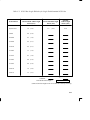
steady amber, this indicates a fault condition. Table 3–1 lists the LED
codes and their meanings.
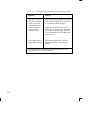
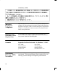
Table 3–1. LED Display Codes – DDS-DC Drive
Cassette
Light
Drive
Light
Meaning
Cassette (un)loading
Cassette loaded/online
Cassette loaded/activity
Cassette loaded/offline
OFF
Green
Amber
Pulsing Green
Pulsing Amber
Pulsing Green
and Amber
Write-Protect States
Cassette (un)loading
Cassette loaded/online
Cassette loaded/activity
Cassette loaded/offline
Error States
Media wear (caution)
High humidity
Self-test (normal)
Self-test (failure)
3-4
Key
LED Warning Conditions – DDS-DC Drive
The following sections describe actions to take if the LEDs indicate a
warning condition.
High Humidity
If the LEDs display the high humidity signal, the humidity is too high
and the drive does not perform any operations until the humidity
drops.
Self-Test (Failure)
If the LEDs display the self-test (failure) signal, a fault was diagnosed
during the self tests. Note the pattern of the pulses and contact your
local service representative.
Media Wear (Caution)
Hewlett-Packard DDS drives continually monitor the number of errors they have to correct when reading and writing to a tape to determine tape wear and tape head cleanliness. If excessive tape wear or
dirty tape heads are suspected, the drive warns you by displaying the
Media Wear (Caution) signal on the LED indicators.
If the LED indicators on your DDS-format drive display the Media
Wear (Caution) condition, follow this procedure:
1.
Check the system console for any tape error messages. A hard
error during a read or write operation may have occurred.
2.
Clean the heads with a cleaning cassette (HP92283K) as described in the “Cleaning the Tape Heads” section, later in this
chapter.
3.
Repeat the operation you performed when the Media Wear (Caution) signal displayed. If the Media Wear (Caution) signal still
displays, then the data cassette should be replaced.
3-5
4.
If you are performing a backup from disk to tape, discard the
data cassette and back up your files using a new data cassette.
5.
If you are performing a restore from tape to disk, complete the
restore, then discard the data cassette and back up the files to a
new data cassette.
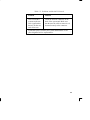
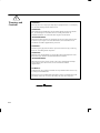
LEDs – DDS-2
The front panel has two colored LEDs: the Tape Light and the Clean/
Attention Light. The Tape Light flashes green to show activity (loading, unloading, reading, and writing). Steady green means a cartridge
is loaded.
The Clean/Attention Light flashes amber to indicate head cleaning is
needed or a cartridge is near the end of its life. Steady amber means a
hard fault.
Table 3–2. LED Display Codes – DDS-2 Drive
Tape
Light
3-6
Clean/
Attention
Meaning
Key
OFF
Activity – load or unload
Steady Green
Activity – read or write
Steady Amber
Cartridge loaded
Flashing Green
1/2 sec on, 1/2 sec off
Any
Cleaning needed
Flashing Amber
1/2 sec on, 1/2 sec off
Any
Fault
Fast Flash Green
1/4 sec on, 1/4 sec off
Data Cassettes
Media Life
HP DDS data cassettes are currently specified to 2000 passes over
any part of the tape under optimal environmental conditions (50%
relative humidity, 22 degrees C). During a tape operation, any one
area of the tape may have multiple passes over the heads. This translates into approximately 200 to 300 backups or restores.
Under certain conditions, the life of your data cassette is less. Replace
your data cassettes after 100 backups or restores if your operating
conditions meet any of the following criteria:
•
•
•
The relative humidity in your operating environment is consistently less than 50%.
You know that the backup software you are using makes multiple passes over sections of the tape during backups or restores.
You notice that when you do backups and restores the tape stops
and starts frequently.
Cleaning the Tape Heads
Clean the heads of your tape drive after every 25 hours of tape drive
use or if the Media Wear (Caution) signal is displayed on the LED.
NOTICE:
Only use HP Cleaning Cassettes (HP92283K)
to clean the tape heads. Do not use swabs or
other means of cleaning the tape heads.
Follow this procedure to clean the tape heads:
1.
Insert the cleaning cassette into the drive. The tape automatically
loads the cassette and cleans the heads. At the end of the cleaning cycle, the drive ejects the cassette.
2.
Write the current date on the label on the cleaning cassette so
that you know how many times you have used it. Discard the
cleaning cassette after you have used it 25 times.
3-7
Media Restrictions
If you interchange media between other HP workstation DDS tape
drives, note that data cassettes with compressed data can only be read
by tape drives that have data compression capabilities. This includes
data cassettes that contain both compressed and noncompressed data.
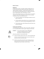
Setting the Write-Protect Tab on a Data Cassette
You can only store or change information on a data cassette when the
write-protect tab is in the write position. So, before trying to write to
the data cassette, make sure that the write-protect tab is in the write
position, as shown in Figure 3–2.
Figure 3–2. Setting the Write-Protect Tab on a DDS Tape
To protect information on a data cassette from being overwritten, set
the write-protect tab to the write-protect position, as shown in
Figure 3–2.
NOTICE:
3-8
The write-protect tab should always be in the
write position for transferring data to a cassette.
Operating the
DDS Tape Drive
This section describes how to perform tasks with your DDS tape
drive.
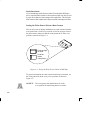
Loading and Unloading a Data Cassette
Follow these steps to load and unload a data cassette in the DDS tape
drive:
1.
Turn on power to the tape drive.
2.
Insert the data cassette into the drive, as shown in Figure 3–3.
Eject Button
Figure 3–3. Loading a Data Cassette
3-9
3.
Push the data cassette about three quarters of the way into the
drive. The drive automatically pulls the data cassette the rest of
the way in. When the LEDs on the front of the drive stop flashing, the drive has loaded the data cassette.
4.
To remove the data cassette, press and release the eject button on
the front of the drive, as shown in Figure 3–3. The LEDs on the
drive flash on and off. Ten to twenty seconds later, the data cassette slides partway out of the drive. Remove the cassette from
the drive.
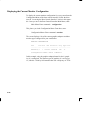
Verifying the DDS Tape Drive Operation
Type the following:
/usr/sbin/ioscan –d stape
3-10
Enter
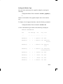
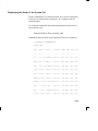
After a few moments the ioscan utility returns a message similar to
the following:
H/W Path
Class
Description
============================================
bc
8
bc
I/O Adapter
8/12
ba
Core I/O Adapter
8/12/5
ext_bus
Built-in SCSI
8/12/5.3
target
8/12/5.3.0
tape
HP
HP35480A
If ioscan does not see your tape drive it will return the following message:
ioscan: No hardware found
If you receive this message, go to Chapter 6, “Solving Problems.”
3-11
Device files are special
files that tell your system
which system hardware
pathway to use when
communicating with a
specific device and what
kind of device it is.
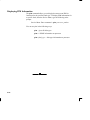
Using Device Files
Your system has four default device files for use with your tape drive:
two device files for noncompressed mode and two device files for
compressed mode. If you use these device files, you do not need to
create any device files.
If the SCSI address of your tape drive is not set to the factory default
of SCSI ID 3, you must create a device file, then substitute the pathname of your device file in the examples that follow. Refer to the System Administration Tasks manual for information on how to create a
device file.
NOTICE:
The device file names depend on the naming
conventions of your particular system. See
“SCSI and Device File Information for HP-UX
10.20 or Later” in Chapter 1 of this book.
Device Files — No Data Compression
Your system has two device files for using your tape drive with data
compression turned off. The device files are named /dev/rmt/3m and
/dev/rmt/3mn, and are set for SCSI ID 3.
If you use the /dev/rmt/3m device file, the tape drive rewinds the
data cassette every time the system releases the drive from its control.
If you use the /dev/rmt/3mn device file, the drive does not rewind
the data cassette. The tape stays where it was after the last operation.
If you use these device files, you do not need to create any device
files.
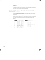
Determining Available Device Files
1.
In a terminal window, enter the following command:
sam
3-12
Enter
2.
The System Administration Manager window opens. Double–
click on Peripheral Devices –>.
3.
The Peripheral Devices window opens. Double–click on Tape
Drives –>.
4.
The Tape Drives window opens.
5.
In the list of tape drives, clock on the desired tape drive to select
it.
6.
From the Action menu, click on Show Device Files.
A window opens with a list of the device files for the selected
tape drive with an explanation of each one.
3-13
Device Files — Data Compression
If you wish to use the data compression feature, use the device files
/dev/rmt/3hc and /dev/rmt/3hcn, which are set for SCSI ID 3.
If you use the /dev/rmt/3hc device file, the tape drive compresses the
data and rewinds the data cassette every time the system releases the
drive from its control.
If you use the /dev/rmt/3hcn device file, the drive compresses the
data, but does not rewind the data cassette. The tape stays where it
was after the last operation.
If you use these device files, you do not need to create any device
files.
The tar (tape file archiver) command saves files
to a data cassette, restores files from a data
cassette, or lists files on
a data cassette.
Archiving Data in Compressed and Noncompressed Mode
This section describes how to transfer data to and from a DDS- format data cassette (saving and restoring) using the HP-UX tar command and your tape drive’s device file.
NOTICE:
Before using your DDS-format tape drive to
back up your file system, make sure you read
the “Media Interchangeability Restrictions”
section later in this chapter.
The tar (tape file archiver) command allows you to save files to a
data cassette, restore files from a data cassette to your system, or list
files on your data cassette.
3-14
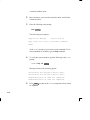
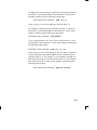
Writing to a Data Cassette
Use the following instructions to save files to a data cassette:
1.
Check that the write-protect tab on the data cassette is in the
write position.
2.
Load the data cassette into the tape drive.
3.
In a terminal window, enter the following command line to write
to the tape:
tar –cvf /dev/rmt/devicefile pathname
Enter
where devicefile is one of the device files listed from sam, and
pathname is the pathname of the file or directory containing files
that you want to write to the tape. To use the data compression
mode, use one of the device file names that sam listed as supporting compression. .
Restoring Files from a Data Cassette to Your System
Use the following instructions to restore files from a data cassette to
your system:
1.
Load the data cassette into the tape drive.
2.
In a terminal window, use cd to change to the directory in which
you want the files to reside.
3.
Enter the following command line:
tar –xvf /dev/rmt/devicefile pathname
Enter
3-15
where devicefile is one of the device files listed from sam, and
pathname is the pathname of the file or directory containing files
that you want to restore from the tape. If pathname is not specified, everything on the data cassette is restored. To use the data
compression mode, use one of the device file names that sam
listed as supporting compression..
3-16
Listing the Files on a Data Cassette
Use the following instructions to list the files on a data cassette:
1.
Load the data cassette into the tape drive.
2.
In a terminal window, enter the following command line to receive a file listing of the data cassette:
tar –tvf /dev/rmt/devicefile
Enter
where devicefile is one of the device files listed from sam. If the
tape was made with data compression, use on the the device file
names that sam listed as supporting compression.
3-17
Further Command Information
The man utility looks up
man pages on the system.
For additional information on using tar and a complete list of the
command arguments, refer to the tar man page by typing the following:
man tar
Enter
You may also communicate with the tape drive with the cpio, ftio,
mt, and fbackup commands. For more information on these commands, enter the following in a terminal window:
man command
Enter
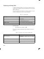
Media Interchangeability Restrictions
If you interchange media between DDS-format tape drives, the following two restrictions apply to the media:
•
•
Data cassettes with compressed data can only be read by tape
drives that have data compression capabilities, such as the tape
drive (part number C1504–67201) found in Kit A2275A #AHS.
Full height (5 1/4-in) DDS-format tape drives (models HP
35470A and HP35480A) can get 1.3 GB and can read or write
to 60-meter data cassettes only, if they are not using data compression. With data compression, these drives can get 2 GB and
can read or write to 90-meter cassettes.
Troubleshooting
If you have trouble with any of these procedures for using your DDS
tape drive, see Chapter 6 of this book, “Solving Problems.”
3-18
Ordering Information
To order Hewlett-Packard data cassettes and cleaning cassettes for use
in your DDS tape drive, use the following order numbers:
•
•
•
•
•
HP92283A
Box of five 60–meter DDS data cassettes
HP92283B
Box of five 90–meter DDS data cassettes
HP92300A
Box of five 120-meter DDS data cassettes
(for DDS-2 drive only)
HP92283K
Package of two cleaning cassettes
HP92283L
Lockable storage box for 12 cassettes
CAUTION: Use only data cassettes labeled as DDS
(Digital Data Storage) cassettes. Never use
audio cassettes labeled DAT (Digital Audio
Tape) in your DDS-format drive.
3-19
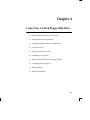
Chapter 4
Using Your 3.5-Inch Floppy Disk Drive
•
Setting the write-protect tab on a diskette
•
Inserting and removing a diskette
•
Verifying the floppy disk drive configuration
•
Using device files
•
Floppy disk drive device file
•
Formatting a new diskette
•
Transferring data to and from a floppy diskette
•
Configuring the floppy driver
•
Troubleshooting
•
Ordering information
4-1
This chapter describes how to perform tasks that allow you to archive
to or transfer data from the optional 3.5-inch floppy disk drive.
The instructions in this chapter assume you are using the HP-UX
version 10.20 or later operating system with the HP VUE version 3.0
interface.
NOTICES: When examples of user input are given in this
chapter, enter them at the command-line prompt
in an HP VUE terminal window or HP-UX
shell.
Some procedures in this chapter require you to
log in as root. If you cannot log in as root, contact your system administrator.
4-2
Using the Floppy
Diskette
This section describes basic information needed for using your floppy
diskettes.
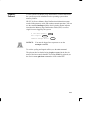
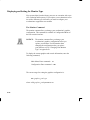
Setting the Write-Protect Tab on a Diskette
You can only store or change information on a diskette when the
write-protect tab is in the write position. So, before trying to write to
the diskette, make sure that the write-protect tab is in the write position, as shown in Figure 4–1.
Push tab up
for write.
Push tab
down for
write-protect.
Figure 4–1. Setting the Write-Protect Tab on a Floppy Diskette
To protect files on a diskette from being overwritten, set the writeprotect tab to the write-protect position.
NOTICE:
The write-protect tab should always be in the
write position for formatting a new diskette and
transferring data to a diskette.
4-3
Inserting and Removing a Diskette
Follow these steps to insert and remove a diskette from the floppy
disk drive:
1.
Insert the diskette into the drive, as shown in Figure 4–2.
Eject Button
Figure 4–2. Inserting and Removing a Floppy Diskette
4-4
2.
Push the diskette into the floppy drive until it clicks into place.
3.
To remove the diskette, push the eject button (see Figure 4–2),
then take out the diskette.
Operating the
Floppy Drive
This section describes how to perform tasks with your 3.5-inch floppy
disk drive.
Verifying the Floppy Drive Configuration
The ioscan utility verifies
the configuration of all
drives.
To verify that your workstation can communicate with the floppy
drive, use the ioscan command in a terminal window to see which
devices are currently in use on your system:
1.
Enter the following at a command prompt:
/usr/sbin/ioscan –d sflop
Enter
After a few moments the ioscan utility lists all of the SCSI
floppy I/O devices it could find. The list appears similar to the
following:
H/W Path
Class
Description
============================================
bc
8
bc
I/O Adapter
8/12
ba
Core I/O Adapter
8/12/5
ext_bus
Built-in SCSI
8/12/5.0
target
8/12/5.0.0
disk
TEAC FC-1
HF 07
If ioscan does not see your floppy drive it returns the following
message:
ioscan: No hardware found
If you receive this message, go to Chapter 6, “Solving Problems.”
4-5
If the floppy driver is not configured, ioscan returns the following message:
ioscan: Device driver scsifloppy is not in the kernel
If you receive this message, go the the section, “Configuring the
Floppy Driver” later in this chapter for information on adding
the scsifloppy driver to the HP-UX kernel configuration.
Using Device Files
Device files are special files that tell your system which pathway to
use through the system hardware when communicating with a specific
device and what kind of device it is.
NOTICE:
The device file names depend on the naming
conventions of your particular system. See
“SCSI ID and Device File Information for HPUX 10.20 or Later” in Chapter 1 of this book.
If you set the SCSI address of your floppy drive to a value other than
0, you must create a device file for it. Refer to the System Administration Tasks manual for information on how to create a device file.
To determine what device files are available for use with your floppy
drive, use the following procedure:
1.
In a terminal window, enter the following command:
sam
4-6
Enter
2.
The System Administration Manager window opens. Double–
click on Disks and File Systems–>.
3.
The Disk and File Systems window opens.
4.
In the list of drives, click on the floppy drive listing to select it.
5.
From the Actions menu, click on View More Information.
A window opens with a list of information for the floppy drive,
inlcuding the device files.
4-7
Formatting a New Diskette
You must always format a new floppy diskette with the mediainit
utility before using it. To format a new floppy diskette follow these
steps:
1.
Log in as root.
2.
Make sure that the write-protect tab on the floppy diskette is in
the write position, as shown in Figure 4–1.
3.
Insert the diskette into the floppy disk drive.
4.
In a terminal window, execute mediainit with an interleave of 2
by entering the following:
mediainit –i 2 devicefile
Enter
where devicefile is the device file as listed by sam.
Transferring Data To and From a Floppy Diskette
The tar (tape file archiver) command saves files
to a floppy diskette, restores files from a floppy
diskette, or lists files on
a floppy diskette.
4-8
This section describes how to transfer data to and from your floppy
diskette (saving and restoring) using the HP-UX tar command with
your floppy drive’s device file.
You need to set the write protect tab to the write position to transfer
data to the diskette. The write-protect tab can be in either position
when restoring data from a diskette or listing the files on a diskette.
Saving Files to a Floppy Diskette
Use the following instructions to save files to a floppy diskette:
1.
Check that the write-protect tab on the floppy diskette is in the
write position.
2.
Load the formatted floppy diskette into the disk drive.
3.
In a terminal window enter the following command line to write
to the diskette:
tar –cvf devicefile pathname
Enter
where devicefile is the device file as listed by sam and pathname
is the pathname of the file or directory containing files that you
want to write to the diskette.
Restoring Files from a Floppy Diskette to Your System
Use the following instructions to restore files from a floppy diskette
to your system:
1.
Load the floppy diskette into the disk drive.
2.
In a terminal window, use the cd command to change to the directory you want the files to reside in:
cd directory_path
Enter
where directory_path is the pathname of the directory.
3.
Enter the following command line:
4-9
tar –xvf devicefile pathname
Enter
where devicefile is the device file as listed by sam and pathname
is the pathname of the file or directory containing files that you
want to restore from the diskette. If you do not specify pathname, everything on the floppy diskette is restored.
Listing the Files on a Floppy Diskette
Use the following instructions to list the files on a floppy diskette:
1.
Load the floppy diskette into the disk drive.
2.
In a terminal window, enter the following command line:
tar –tvf devicefile
Enter
where devicefile is the device file as listed by sam
All files on the floppy diskette are listed.
For More Information
The man utility looks up
man pages on the system.
For more information on using tar and a complete list of the command arguments, refer to the tar man page by typing the following in
a terminal window:
man tar
Enter
You can mount the floppy drive as a file system using the SAM utility. Be sure to unmount the drive before removing it as a file system.
For more information about how to mount and unmount the floppy
drive, see the manual Using HP-UX (B2910–90001).
For more information on copying data to or from your system to other
media, including your floppy diskette, refer to the cpio man page by
typing the following in a terminal window:
4-10
man cpio
Enter
For more information on copying to or from DOS files, refer to the
doscp man page by typing the following in a terminal window:
man doscp
Enter
For more information on listing DOS directories, refer to the dosls
man page by typing the following in a terminal window:
man dosls
Enter
For more information on using your floppy disk drive and floppy diskettes, refer to the floppy man page by typing the following in a terminal window:
man floppy
Enter
For more information on using the mediainit command, refer to the
mediainit man page by typing the following in a terminal window:
man mediainit
Enter
4-11
Configuring the Floppy Driver
If you reload software or rebuild the Instant Ignition system on your
workstation, you need to reconfigure the HP-UX Kernel to add the
floppy driver. Use the SAM utility to add the SCSI flexible disk driver and build a new HP-UX kernel.
For more information about how to reconfigure the kernel using
SAM, see the following manuals:
•
•
System Administration Tasks HP 9000 Series 700 Computers
(B2355–90040)
Using HP-UX (B2910–90001)
Troubleshooting
If you have trouble with any of these procedures for using your
floppy disk drive, see Chapter 6 of this book, “Solving Problems.”
Ordering Information
To order Hewlett-Packard micro flexible diskettes for use in your
3.5-inch floppy disk drive, use the following order number:
HP–92192X
4-12
High-Density Micro Flexible Disks
(1.44MB Formatted Capacity) – box
of ten diskettes
Chapter 5
Solving Problems
•
Common problems and solutions
•
Dealing with a boot failure
•
Memory failures
•
LCD-indicated problems
•
Running system verification tests
5-1
This chapter contains information to help you determine what’s
wrong with your system when you have problems. If you have a
problem that isn’t listed in this chapter, or if your problem persists,
contact your designated service representative. When calling for service, always have your system’s model number and serial number
ready.
The instructions in this chapter assume you are using the HP-UX
version 10.20 or later operating system with the HP VUE version 3.0
graphical interface. If your system is configured with the HP CDE
graphical user interface, use command line options in a terminal window to perform tests.
5-2
Common
Problems and
Solutions
The tables in this section list common problems you may encounter
with your workstation. The tables also tell you what to do to help
solve the problems.
Table 5–1. Problems Powering Up the System
Problem
Solution
The power LED
doesn’t light.
Make sure all ac power cables are
connected securely to the system.
Make sure the power cord is plugged
into a working ac outlet.
Make sure the power switch is set to
the ON position.
The power LED
lights, but the screen
is blank or flickers
Press the brightness control on the
monitor to adjust it. If the screen is
still blank, turn off the system and
monitor power switches. When the
system is completely powered off,
check the video cable connections.
Go to the section “Changing Your
Monitor Type” in Appendix B for information about displaying and setting
your workstation’s monitor configuration.
LCD messages
See “LCD-Indicated Problems” later
in this chapter.
If problems persist, contact your system administrator or call
your designated service representative.
5-3
Table 5–2. Problems Loading and Booting the Operating System
Problem
Solution
The power LED is
lit, and text appears
on the screen, but
more than two minutes have passed
with no sign of
system activity.
Make sure that all SCSI devices are set
to the proper SCSI ID. (See Appendix
C for default SCSI ID settings.)
The system stops or
hangs while booting.
Follow the instructions in “Dealing
With a Boot Failure,” later in this
chapter.
Check that all SCSI devices are correctly cabled. Check that the SCSI bus
is correctly terminated. (See Appendix
C for information on SCSI cabling and
termination.)
If problems persist, contact your system administrator or call
your designated service representative.
5-4
Table 5–3. Problems with the 802.3 Network
Problem
Solution
Can’t reach other
systems on the network. Applications
that rely on the network won’t run.
Check the network connector on the
back of the system unit. Make sure
that the network cable or transceiver is
fastened securely to the connector.
If problems persist, contact your system administrator or call
your designated service representative.
5-5
Table 5–4. Problems Using a Hard Disk Drive
Problem
Solution
The disk drive is not
accessible or does
not respond.
Make sure that all SCSI devices are
set to the proper SCSI ID. (See Appendix C for default SCSI ID settings.)
Check that all SCSI devices are correctly cabled. Check that the SCSI bus
is correctly terminated. (See Appendix
C for information on SCSI cabling
and termination.)
Make sure that the system can communicate with the drive as described
in “Checking the SCSI IDs” in Appendix B.
Follow the instructions in “Dealing
With a Boot Failure” later in this
chapter.
If problems persist, contact your system administrator or call
your designated service representative.
5-6
Table 5–5. Problems Using the CD-ROM Drive
Problem
Solution
The CD-ROM drive
does not respond to
commands.
Re-enter the commands and make
sure that you have typed them correctly.
Make sure that the system can communicate with the drive as described
in “Checking the SCSI IDs” in
Appendix B.
Follow the instructions in the section
entitled “Running System Verification Tests” later in this chapter to
verify that the CD-ROM drive is
functioning properly.
If problems persist, contact your system administrator or call
your designated service representative.
5-7
Table 5–6. Problems Using the DDS Tape Drive
Problem
Solution
The DDS tape drive
does not respond to
commands.
Re-enter the commands and make sure
that you have typed them correctly.
Make sure that you specified the correct device file name for commands
that require a device file name.
Make sure the write-protect tab is set
to write if you are trying to copy data
to a data cassette.
Make sure that the system can communicate with the drive as described
in “Checking the SCSI IDs” in Appendix B.
Follow the instructions in the section
entitled “Running System Verification
Tests” later in this chapter to verify
that the tape drive is functioning properly.
If problems persist, contact your system administrator or call
your designated service representative.
5-8
Table 5–7. Problems Using the Floppy Disk Drive
Problem
Solution
The floppy drive
does not respond to
commands.
Re-enter the commands and make sure
that you have typed them correctly.
Make sure that you specified the device file /dev/rfloppy/c201d0s0 for
commands that require a device file
name.
Make sure that the write-protect tab is
set to write if you are trying to copy
data to a floppy diskette.
Follow the instructions in the section
entitled “Running System Verification
Tests” later in this chapter to verify
that the floppy drive is functioning
properly.
If problems persist, contact your system administrator or call
your designated service representative.
5-9
Dealing with a
Boot Failure
If your usual boot device (typically a disk) is not responding as it
should, you must try to boot from the disk (or another boot device) by
selecting it manually.
To boot a device manually, follow these steps:
1.
Follow the directions in “Accessing the Boot Console Interface,”
in Appendix D of this book.
NOTICE:
2.
Your workstation automatically shuts down the
operating system before it terminates the power.
At the Main Menu prompt, type the following:
Main Menu: Enter a command or a menu > search ipl
The search command
looks for bootable media
on your workstation.
Enter
This causes your workstation to search exhaustively for bootable
media.
3.
Boot from one of the listed devices by typing the following at
the prompt:
Main Menu: Enter a command or a menu > boot device
Enter
where device is the hardware path to the device, specified in
mnemonic style notation, such as FWSCSI.5.0.
4.
5-10
If your workstation still fails to boot, there is either something
wrong with the file system or with the hardware. If you suspect a
file system failure, see the manual Using HP-UX for help on
dealing with file system failures. If you think that something is
wrong with the hardware, continue reading this chapter for more
troubleshooting information.
Memory
Failures
J Class systems use Memory Page Deallocation, a feature that allows
the system to provide information to the operating system about
memory failures.
HP-UX 10.20 uses Memory Page Deallocation information to map
out the failing memory areas, and continue normal operation. You can
use the command memrpt with the detail switch to obtain information about the Memory Page Deallocation Table (PDT) as well as
single bit errors logged by the system.
# /usr/sbin/sysdiag
DUI >logtool
Enter
LOGTOOL> memrpt detail
NOTICE:
Enter
Enter
You must be logged in as superuser to use the
memrpt command.
To exit the sysdiag and logtool utilities, use the exit command.
The pdt can also be checked using the pdt command in the Service
menu of the boot console handler. If a failing DIMM is replaced, use
the Service menu pdt clear command to clear out the PDT.
5-11
LCD-Indicated
Problems
Your workstation uses an LCD panel to display firmware/OS progress
codes. The codes, referred to as chassis codes, consist of one of the
mnemonics listed below, followed by a 4-digit hex number identifying the code module being executed. The mnemonics and their meaning are:
•
FLT – A hardware error has been detected
•
TEST – Hardware being tested
•
INIT – Hardware being initialized
•
SHUT – System being shutdown
•
WARN – A non-optimal operating condition exists
•
RUN – System is running operating system
During a normal boot sequence, a set of “windows” appear. In general, the LCD display has the following format:
♥
ZZZZ
YYYY
CPUXX
♥
WWWWWWWWWWWWWWWW
5-12
>
>
>
>
>
← ← 4 character OSTAT
4 digit hex code
Functional CPUs in system
Heart beat
Text Diagnostic Message
The windows are as follows:
Window 1
When the system is hard booted, the LCD will be cleared and the following message will be displayed for approximately 1 second. Then
the processor dependent hardware (pdh) is verified.
Proceeding To
Turn DC On
<– line 1
<– line 2
Window 2
While the pdh is being verified, the following message is displayed:
ZZZZ YYYY
Selftest Sys Bd
<– line 1
<– line 2
Window 3
After the pdh is verified, the selftest is executed. The display changes
to:
ZZZZ YYYY
Selftest
♥
<– line 1
<– line 2
– ’♥’ flashes with Z Y field change
Window 4
When the selftest is complete, the message (once the console is
found) is:
ZZZZ YYYY CPUXX♥ <– line 1
AAAAAAAA console <– line 2
– ’♥’ flashes with Z Y field change
where AAAAAA is RS-232A, RS-232B, or GRAPHICS.
5-13
Window 5
When an attempt to boot is made, the following message is displayed
once IPL is successfully loaded and launched:
ZZZZ YYYY CPUXX♥ <– line 1
BBBBBBBBBBBBBBBB <– line 2
– ’♥’ flashes with Z Y field change
where BBBBBBBBBBBBBBBB is the model number (for example,
9000/J200).
If the system encounters an FLT code while the system is booting, the
FLT code is interpreted and one of the following messages is displayed:
FLT CODE MESSAGES
1.
2.
3.
4.
5.
6.
7.
8.
5-14
Selftest Sys Bd
Selftest
cpu X
Selftest EISA X
Selftest DIMM XX
Selftest Mem Sys
Selftest Graph X
Unexp. Trap XX
HPMC occurred !
Meaning of X
(0 or 1)
(0 to 4)
(DIMM pair 0 to 7)
(0 to 2)
(0 to 28)
Running System
Verification
Tests
HP-UX uses a diagnostics product called the Support Tools Manager
that allows system operation verification.
You can access the Support Tools Manager in a terminal window. If
you are using HP VUE as your interface, you can also access the Support Tools Manager through the sys_admin directory.
Three interfaces are available with the Support Tools Manager: a
command line interface (accessed through the cstm command), a
menu-driven interface (accessed through the mstm command), and
the graphical user interface (accessed through the xstm command).
For more information on these user interfaces, see the online man
pages by entering the following at a command line prompt:
man cstm
man mstm
man xstm
Enter
Enter
Enter
To access the Support Tools Manager, perform the following steps:
1.
Click on the Terminal Control on the Front Panel of your
Workspace.
Terminal Control
5-15
A terminal window opens.
2.
Move the mouse cursor into the terminal window and click the
left mouse button.
3.
Enter the following at the prompt:
cstm
Enter
The following screen appears:
Support Tool Manager
Version A.01.00
Type ’help’ for a list of available commands.
CSTM>
At the CSTM> prompt, you can enter several commands. To see
what commands are available, type the help command.
4.
To verify the system operation, type the following at the CSTM>
prompt:
CSTM> verify all
Enter
Messages similar to the following appear:
Verification has started on device (CPU).
Verification has started on device (FPU).
CSTM>Verification of (FPU) has completed.
CSTM>Verification of (CPU) has completed.
5.
5-16
Press Enter to return to the CSTM> prompt after all test results
are reported.
6.
To exit the Support Tools Manager, type the following:
CSTM> exit
Enter
If any tests failed, further diagnosis is necessary by qualified service
personnel. Contact your designated service representative.
5-17
Appendix A
Safety and Regulatory Statements
•
Declaration of conformity
•
Emissions regulations
•
Emissions regulations compliance
•
Datacom users statement
•
Acoustics
•
Electrostatic discharge (ESD) precautions
•
Laser safety statements
•
Warnings and cautions
This appendix contains safety and regulatory statements pertaining to
your J 280 workstation.
A-1
A-2
Emissions
Regulations
Federal Communications Commission (FCC)
This equipment has been tested and found to comply with the limits
for a Class B digital device, pursuant to part 15 of the FCC Rules and
the Canadian Department of Communications. These limits are designed to provide reasonable protection against harmful interference
in a residential installation. This equipment generates, uses, and can
radiate radio frequency energy and, if not installed and used in accordance with the instructions may cause harmful interference to radio
communications. However, there is no guarantee that interference will
not occur in a particular installation. If this equipment does cause
harmful interference to radio or television reception (determined by
turning the equipment off and on), you can correct the interference by
one or more of the following measures:
•
•
•
•
Reorient or relocate the receiving antenna.
Increase the separation between the equipment and the receiver.
Connect the equipment into an outlet on a circuit different from
that to which the receiver is connected.
Ask the dealer or an experienced radio/television technician for
help.
Hewlett-Packard’s system certification tests were conducted with HPsupported peripheral devices and HP shielded cables, such as those
you receive with your computer. Changes or modifications not expressly approved by Hewlett-Packard could void the user’s authority
to operate the equipment.
Operation of this device is subject to the following conditions:
•
•
•
This device may not cause harmful interference.
This device must accept interference received, including interference that may cause undesired operation.
Cables used with this device must be properly shielded to comply with the requirements of the FCC.
A-3
VCCI Class 1 ITE
Emissions
Regulations
Compliance
Any third-party I/O device installed in HP system(s) must be in accordance with the requirements set forth in the preceding Emissions
Regulations statements. In the event that a third-party noncompliant
I/O device is installed, the customer assumes all responsibility and
liability arising therefrom.
Datacom Users
Statement (United
Kingdom Only)
The HP 9000 J 280 is approved under Approval Number NS/
G/1234/J/100003 for indirect connection to Public Telecommunications systems within the United Kingdom.
Acoustics
Regulation On Noise Declaration For Machines –3. GSGV
Lpa <70dB
operator position
normal operation
per ISO 7779
Electrostatic
Discharge (ESD)
Precautions
A-4
Lpa <70dB
am Arbeitsplatz
normaler Betrieb
nach DIN 45635 T.19
Electrostatic charges can damage the integrated circuits on printed
circuit boards. To prevent such damage from occurring, observe the
following precautions during board unpacking and installation:
•
•
•
•
•
Laser Safety
Statement (For
U.S.A. Only)
Stand on a static-free mat.
Wear a static strap to ensure that any accumulated electrostatic
charge is discharged from your body to ground.
Connect all equipment together, including the static-free mat,
static strap, routing nodes, and peripheral units.
Keep uninstalled printed circuit boards in their protective antistatic bags.
Handle printed circuit boards by their edges, once you have removed them from their protective antistatic bags.
(For workstations that have a CD ROM drive installed.)
The CD-ROM mass storage system is certified as a Class 1 laser
product under the U.S. Department of Health and Human Services
(DHHS) Radiation Performance Standard according to the Radiation
Control for Health and Safety Act of 1968.
This means that the mass storage system does not produce hazardous
laser radiation. Because laser light emitted inside the mass storage
system is completely confined within protective housings and external covers, the laser beam cannot escape from the machine during any
phase of user operation.
IEC 825 Class 1
Laser Label
CLASS 1 LASER PRODUCT
LASER KLASSE 1
A-5
Warnings and
Cautions
WARNING:
Removing device cover may expose sharp edges in equipment chassis. To avoid injury,
use care when installing customer add-on devices.
WARNUNG:
Das Entfernen der Geräteabdeckung legt die scharfen Kanten im Inneren des Gerätes
frei. Um Verietzungen zu vermeiden, seien Sie vorsichtig beim Einbau von
zusätzlichen Bauteilen, die vom Kunden selber eingebaut werden können.
AVERTISSEMENT:
Des bords tranchants du châssis de l’équipement peuvent être exposés quand le cache
de l’unité n’est pas en place. Pour éviter des blessures, faire très attention lors de
l’installation de modules supplémentaires par le client.
WARNING:
Disconnect power plug from wall outlet or power source before moving or removing
the device, or installing add-on components.
WARNUNG:
Entfernen Sie die Stromzuführung von der Steckdose oder der Stromquelle bevor Sie
das Gerät bewegen, abbauen, oder zusätzliche Bauteile installieren.
AVERTISSEMENT:
Débrancher la fiche de la prise de courant ou de la source d’alimentation électrique
avant de déplacer ou de retirer l’unité, ou avant d’installer des modules
supplémentaires.
WARNING:
Lithium batteries may explode if mistreated. Do not put lithium batteries in fires or try
to recharge or disassemble them.
Replace battery only with Matsushita Electric BR–2325 three-volt lithium battery (HP
part number 1420–0314)! Use of any other battery may cause fire or explosion.
A-6
Appendix B
Changing Your Workstation’s
Hardware Configuration
•
Checking the SCSI IDs
•
Opening the system unit
•
Closing the system unit
•
Installing removable media devices
•
Adding a hard drive
•
Installing additional memory
•
Installing an EISA or graphics board
•
Changing your monitor type
B-1
This appendix describes the procedures to change your workstation’s
hardware configuration.
The instructions in this appendix assume you are using the HP-UX
version 10.20 or later operating system with the HP VUE version 3.0
interface.
CAUTION: Always wear a properly grounded wrist strap
when reconfiguring your workstation.
Use the following tools to remove or replace hardware parts when
changing your configuration:
•
Light-duty flat blade screwdriver with 150 mm (6 in.) blade
•
Number 1 Posi-drive driver
•
Needlenose pliers
Also, read the ESD Precautions in Appendix A of this guide.
B-2
Checking the
SCSI IDs
To determine which SCSI IDs are currently in use on your system,
use the ioscan command in a terminal window:
1.
Click on the Terminal Control on the Front Panel of your
Workspace.
Terminal Control
A terminal window opens.
2.
Move the mouse cursor into the terminal window and singleclick the left mouse button.
3.
Enter the following at the prompt:
/usr/sbin/ioscan –f
Enter
After a few moments the ioscan utility lists all of the SCSI I/O
devices it could find. The list appears similar to the following:
Class
I H/W Path
Driver
S/W State H/W Type Description
==========================================================================
bc
0
root
CLAIMED
BUS_NEXUS
bc
1 8
ccio
CLAIMED
BUS_NEXUS I/O Adapter
ext_bus
0 8/0
c720
CLAIMED
INTERFACE GSC built-in Fast/Wide SCSI Interface
target
0 8/0.0
tgt
CLAIMED
DEVICE
B-3
disk
target
disk
target
disk
ba
ext_bus
audio
tty
ext_bus
target
disk
target
tape
target
disk
target
disk
lan
ps2
bc
graphics
graphics
ext_bus
target
disk
graphics
ba
tty
ba
ext_bus
target
disk
target
disk
target
disk
processor
memory
B-4
3
1
2
2
0
0
2
0
0
1
3
1
4
0
5
10
6
5
0
0
2
0
1
3
7
6
2
1
1
2
4
8/0.0.0
8/0.5
8/0.5.0
8/0.6
8/0.6.0
8/12
8/12/0
8/12/1
8/12/4
8/12/5
8/12/5.2
8/12/5.2.0
8/12/5.3
8/12/5.3.0
8/12/5.4
8/12/5.4.0
8/12/5.6
8/12/5.6.0
8/12/6
8/12/7
10
10/0
10/8
10/12
10/12.4
10/12.4.0
10/16
10/20
10/20/2
10/20/5
10/20/5/3
sdisk
tgt
sdisk
tgt
sdisk
bus_adapter
CentIf
audio
asio0
c700
tgt
sdisk
tgt
stape
tgt
sdisk
tgt
sdisk
lan2
ps2
ccio
graph3
graph3
c720
tgt
sdisk
graph3
bus_adapter
asio0
eisa
hshpib
CLAIMED
CLAIMED
CLAIMED
CLAIMED
CLAIMED
CLAIMED
CLAIMED
CLAIMED
CLAIMED
CLAIMED
CLAIMED
CLAIMED
CLAIMED
CLAIMED
CLAIMED
CLAIMED
CLAIMED
CLAIMED
CLAIMED
CLAIMED
CLAIMED
CLAIMED
CLAIMED
CLAIMED
CLAIMED
CLAIMED
CLAIMED
CLAIMED
CLAIMED
CLAIMED
CLAIMED
DEVICE
DEVICE
DEVICE
DEVICE
DEVICE
BUS_NEXUS
INTERFACE
INTERFACE
INTERFACE
INTERFACE
DEVICE
DEVICE
DEVICE
DEVICE
DEVICE
DEVICE
DEVICE
DEVICE
INTERFACE
INTERFACE
BUS_NEXUS
INTERFACE
INTERFACE
INTERFACE
DEVICE
DEVICE
INTERFACE
BUS_NEXUS
INTERFACE
BUS_NEXUS
INTERFACE
8
10/20/5/3.0
tgt
CLAIMED
DEVICE
10/20/5/3.0.0
10/20/5/3.1
10/20/5/3.1.0
10/20/5/3.2
10/20/5/3.2.0
32
cs80
tgt
cs80
tgt
cs80
processor
CLAIMED
CLAIMED
CLAIMED
CLAIMED
CLAIMED
CLAIMED
DEVICE
DEVICE
DEVICE
DEVICE
DEVICE
PROCESSOR
disk 07959
49
memory
CLAIMED
MEMORY
Memory
7
9
8
10
9
0
0
QUANTUM LPS1080WD
DEC
DSP3210SW
DEC
DSP3210SW
Core I/O Adapter
Built-in Parallel Interface
Built-in Audio
Built-in RS-232C
Built-in SCSI
TOSHIBA CD-ROM XM-4101TA
HP
HP35480A
SEAGATE ST3600N
MICROP 2112
Built-in LAN
Built-in Keyboard/Mouse
I/O Adapter
Graphics
Graphics
GSC add-on Fast/Wide SCSI Interface
SEAGATE ST31200W
Graphics
Core I/O Adapter
Built-in RS-232C
EISA Bus Adapter
EISA card HWP0C70
disk 07959
disk 07959
Processor
4.
You can determine which SCSI IDs are currently in use by looking under the H/W Path heading. The listing 2.0.1 scsi is the
built-in SCSI bus controller. For devices connected to the builtin SCSI bus, such as disks, the fourth number is the SCSI ID for
that device. For example, the listing 2.0.1.6.0 in the sample device list tells you that there is a SCSI device (a disk) currently
using ID 6 on the SCSI bus.
The information is presented in a different format if you are
using HP-UX 10.0 or later; although you still look under the
H/W Path heading.
NOTICE:
Never use SCSI address 7 for any device. Address 7 is reserved for the SCSI controller.
B-5
Opening the
System Unit
B-6
Perform the following steps to open the system unit:
1.
Power off the system, the monitor, and any peripheral devices.
Unplug the system unit power cord and the power cord of any
peripheral devices from ac wall outlets. Refer to Using Your HP
Workstation for the proper method of shutting down your workstation.
2.
Attach the static-grounding wrist strap by following the instructions on the package. Attach the sticky end of the wrist strap to
bare metal on the back panel of the system unit.
3.
Press down on the two buttons on the top front of the workstation, releasing the front panel (also known as the front bezel) as
shown in Figure B–1.
Figure B–1. Removing the Front Panel
4.
Swing the panel down and pull up slightly so the two guide pins
on the bottom clear their guides and lay the front cover down.
B-7
Closing the
System Unit
Perform the following steps to close the system unit:
CAUTION: Do not attempt to operate the workstation with
the front cover removed. The cover is needed
for proper air flow for system cooling.
1.
Insert the two guide pins on the bottom of the front cover into
the guides on the bottom of the system unit.
2.
Swing the front cover up, and push it firmly into the workstation
housing. The front panel edges automatically align with the
workstation housing, and the top latch buttons pop up into position. See Figure B–2.
NOTICE:
B-8
To maintain FCC/EMI compliance, verify that
the top latches snap completely into position.
Figure B–2. Replacing the Front Panel
3.
Reconnect the power cables and any other cables that you disconnected when opening the workstation, then power on any peripherals, the monitor, and the system unit.
B-9
Installing
Removable
Media Devices
Your workstation can have any two of the following removable media
devices, with no two the same:
•
CD-ROM drive
•
2 to 8 GB, 4 mm DDS tape drive
•
3.5-inch Floppy disk drive
Follow these steps for installing any of the removable media drives
into the Storage Assembly. The steps for checking and setting drive
jumpers are different for each drive. Jumper information for each
drive is included in these steps.
NOTICE:
Before opening the system unit, follow the
instructions in “Checking the SCSI IDs,” earlier
in this appendix, to determine the SCSI IDs
currently in use on your workstation.
1.
Open the system unit according to the directions in “Opening the
System Unit,” earlier in this appendix.
2.
Unscrew the two captive screws on the left side of the Storage
Assembly and pull down the drawer ejector handle on the right
side of the Storage Assembly, as shown in Figure B–3.
The Storage Assembly slides partway out of the drawer.
B-10
Figure B–3. Removing Storage Drawer from System Unit
3.
Pull the Storage Assembly out as far as it will go. (A safety catch
prevents the drawer from coming all the way out.)
NOTICE:
4.
When sliding the Storage Assembly out of the
system unit, move the drawer ejector handle to
prevent the Storage Assembly from hitting it.
Push in on the safety catch and continue pulling the drawer out.
Be sure to support the drawer from the bottom.
B-11
5.
Set the drawer on a flat surface.
6.
Disconnect the power distribution cable from the Fan extender
cable.
Figure B–4. Removing EMI Plate
7.
B-12
Disconnect the Fan extender cable form the SCSI PCA.
Figure B–5. Removing FAN/EMI Plate
8.
Unscrew the captive screw holding the FAN/EMI plate at the
back of the removable drives and lift the plate up and out of the
drawer, as shown in Figure B–45
9.
Disconnect the SCSI and power cables from the drive.
B-13
10. Unscrew the two screws holding the drive in the storage drawer,
and slide the drive out of the drawer. See Figure B–6.
Figure B–6. Removing Drive Screws
11.
B-14
Check the SCSI address/jumper settings on the replacement
drive, using the following information sections.
CD-ROM Drive
The CD-ROM drive ships with the drive set to SCSI ID address
2. We recommend keeping the address setting at 2 unless it is
used by another device.
CAUTION: CD-ROM drives are susceptible to mechanical
and electrostatic shock. When handling the drive,
always wear the static-grounding wrist strap that
came in the CD-ROM drive kit. Always handle
the drive carefully.
If you need to change the CD-ROM drive’s address, follow these
instructions, referring to Figure B–7. If you do not need to
change the drive’s address, go to Step 10 of this installation procedure.
1.
Locate the jumpers at the back of the CD-ROM drive.
2.
To change the address, use needlenose pliers to set the
drive’s SCSI ID to an address that is not used by another
SCSI device. Check that the other jumpers are set correctly.
NOTICE:
3.
Do not use SCSI ID 7 for your CD-ROM drive’s
SCSI address. The host SCSI controller uses
SCSI ID 7.
Use needlenose pliers to remove the SCSI terminators, if
still attached to the drive.
B-15
SCSI ID
Address
0
1
2
3
4
Jumpers
ID 1
ID 2
ID 4
TERM
TEST
PRV/ALM
PRTY
ID 4
ID 2
ID 1
5
6
7
Figure B–7. CD-ROM Drive SCSI Address/Jumper Settings
B-16
DDS Tape Drive
The DDS tape drive ships with the drive set to SCSI ID address
3 and the Operation Mode switches set for correct drive operation. We recommend keeping the address setting at 3 unless it is
used by another device.
CAUTION: SCSI tape drives are susceptible to mechanical
and electrostatic shock. When handling the drive,
always wear the static-grounding wrist strap that
came in the DDS tape drive kit. Always handle
the drive carefully.
If you need to change the DDS tape drive’s address or operation
mode, follow these instructions, referring to Figure B–8 for the
DDS-DC drive, Figure B–9 for the DDS-2 drive, and Figure
B–10 for operation mode. If you do not need to change the
drive’s address or operation mode, go to Step 10 of this installation procedure.
1.
Locate the jumpers at the back of the DDS tape drive.
2.
To change the jumper settings, use needlenose pliers to set
the drive’s SCSI ID to an address that is not used by another
SCSI device. Check that the other jumpers are set correctly.
NOTICE:
Do not use SCSI ID 7 for your DDS tape drive’s
SCSI address. The host SCSI controller uses
SCSI ID 7.
3.
Use needlenose pliers to remove the SCSI terminators, if
still attached to the drive.
4.
If you need to change the Operation Mode switches, locate
the switches on the underside of the DDS tape drive.
Switches 1 and 2 are used to configure the data compression
operation mode. Switches 3 through 8 are used to specify
drive connectivity and functionality according to host or
customer requirements. The default setting is all switches
ON. Figure B–10 shows the available options.
B-17
SCSI Terminators
(must be removed)
Target
ID
Term
PWR
ID2
Jumpers
ID1
ID0
Target
ID
0
4
1
5
2
6
Term
PWR
ID2
Jumpers
ID1
ID0
3
(Default)
Figure B–8. DDS-DC Tape Drive SCSI Address/Jumper Settings
B-18
Bit 0
Bit1
Bit 2
Term
PWR
SCSI Connector
SCSI
ID
Term
PWR* Bit 2
Power Connector
Bit 1
Bit 0
SCSI
ID
0
4
1
5
2
6
Term
PWR* Bit 2
Bit 1
Bit 0
3
(Default)
*Term PWR is not used in HP workstation configurations.
Figure B–9. DDS-2 Tape Drive and SCSI Address/Jumper Settings
B-19
Operation Mode
Switches
ON
ON
1 2 3 4 5 6 7 8
1 2 3 4 5 6 7 8
Compression Disabled,
No Host Control
Compression Enabled,
No Host Control
ON
ON
1 2 3 4 5 6 7 8
1 2 3 4 5 6 7 8
Compression Disabled, Host
Can Control Compression
Compression Enabled,
With Host Control
Figure B–10. Switch Settings for Data Compression Operation Mode
B-20
Floppy Drive
The floppy disk drive ships with the drive set to SCSI ID
address 0. We recommend keeping the address setting at 0
unless it is used by another device.
CAUTION: Floppy disk drives are susceptible to mechanical
and electrostatic shock. When handling the drive,
always wear the static-grounding wrist strap that
came in the floppy disk drive kit. Always handle
the drive carefully.
If you need to change the floppy disk drive’s address, follow
these instructions, referring to Figures B–11 and B–12. If you do
not need to change the drive’s address, go to Step 10 of this
installation procedure.
1.
Locate the jumpers on the top of the floppy drive.
2.
To change the jumpers, use needlenose pliers to set the
drive’s SCSI ID to an address that is not used by another
SCSI device. Check that the other jumpers are set correctly.
NOTICE:
3.
Do not use SCSI ID 7 for your floppy drive’s
SCSI address. The host SCSI controller uses
SCSI ID 7.
Use needlenose pliers to remove the SCSI terminators, if
still attached to the drive.
B-21
Jumper in = 0; out = 1
Top View of Floppy Disk Drive
Å
ID 2 ID 1 ID 0
SCSI ID Address Jumpers
SCSI ID Address Jumpers
SCSI ID
Address
Å
Å
Jumpers
ID 2
ID 1
ID 0
0
1
2
3
4
5
6
7
Figure B–11. Floppy Drive SCSI Address/Jumper Settings
B-22
Top View of Floppy Disk Drive
ÅÅ
ÅÅ
SCSI Terminators
1
23
ÅÅ
ÅÅ
Figure B–12. Floppy Drive Terminators
B-23
12. Figure B–13 shows the orientation of each of the removable media drives in the bracket and the position of the screws holding
the drive bracket in place. The same bracket can be used on all
three drives.
Figure B–13. Attaching Removable Drive Mounting Bracket and Drive Orientation
B-24
13. With the disk mounting bracket between the guides on each side
of the Storage Assembly, slide the disk into the Storage Assembly, securing it with the two side screws. See Figure B–14. Do
not over-tighten the side screws.
Reconnect the drive
SCSI and power cables
here.
Figure B–14. Replacing Drive Screws
14. Reconnect the cabling from the back of the drive to the side of
the drawer assembly. See Figure B–14.
15. Secure the EMI plate at the back of the removable drives with
the captive screw in the bottom of the plate.
16. Slide the drawer back in.
B-25
17. Push the drawer ejector handle up until the Storage Assembly
slides all the way into the system unit and secure the two captive
screws on the left of the Storage Assembly, as shown in
Figure B–15.
NOTICE:
If the ejector handle is not pushed completely
in, you may not have proper seating of the SCSI
PCB interconnect to the backplane.
Figure B–15. Replacing the Storage Drawer Assembly
B-26
18. Follow the instructions in “Checking the SCSI IDs” earlier in
this appendix, to verify that your workstation can see the newly
installed drive.
For information about using your drives see the following chapters in
this book:
•
Using your CD-ROM drive is in Chapter 3.
•
Using your DDS tape drive is in Chapter 4.
•
Using your floppy drive is in Chapter 5.
B-27
Adding a
Hard Drive
This section describes how to add a hard drive to your workstation.
The first part deals with installing a hard drive and the second part
tells you how to configure your hard disk after it is installed.
Your workstation can have two hard drives. The hard drive that came
with your workstation was set to SCSI ID 6. If you are adding a second hard disk, the second hard disk will use SCSI ID 5. If another
device on your workstation is using SCSI ID 5, change the hard disk’s
SCSI ID to an unused SCSI ID.
NOTICE:
Do not use SCSI ID 7 for your hard drive’s
SCSI address. The host SCSI controller uses
SCSI ID 7. If you are adding a second hard
drive, we advise you not to use SCSI ID 6
which is normally reserved for the boot disk
drive.
Check the jumpers on the hard drive you plan to install. Figure B–16
shows the correct SCSI address for the jumpers on your drive. These
jumpers are the only jumpers you may need to change on the drive.
1.
Use a pair of small needle-nose pliers to set the SCSI ID
jumpers to SCSI ID 5 if you are adding a second hard drive,
or SCSI ID 6 if this is the first hard drive (you are running
diskless). Check that the other jumpers are set correctly.
2.
If you removed the disk drive mounting bracket from the
disk drive, replace it now, making sure not to over-tighten
the screws. Figure B–17 shows the orientation of the drive
in the bracket for both drives and the position of the screws
holding the drive bracket in place.
Be sure the printed circuit side of one drive is facing the
printed circuit side of the other drive.
B-28
6
5
4
3
2
1
0
15
14
13
12
11
10
9
8
Figure B–16. Fast, Wide Hard Drive Jumper Settings
B-29
Top Drive
PCB Side of Drive
Bottom Drive
Figure B–17. Replacing Hard Drive Mounting Bracket and Drive Orientation
B-30
Installing a Hard Disk Drive
Perform the following steps to install a hard disk drive.
NOTICE:
Before opening the system unit, follow the
instructions in “Checking the SCSI IDs,” earlier
in this appendix, to determine the SCSI IDs
currently in use on your workstation.
1.
Open the system unit according to the directions in “Opening the
System Unit,” earlier in this appendix.
2.
Unscrew the two captive screws on the left side of the Storage
Assembly and pull down the drawer ejector handle on the right
side of the Storage Assembly, as shown in Figure B–18.
The Storage Assembly slides partway out of the drawer.
B-31
Figure B–18. Removing Storage Drawer from System Unit
3.
Pull the Storage Assembly out as far as it will go. (A safety catch
prevents the drawer from coming all the way out.)
NOTICE:
4.
B-32
When sliding the Storage Assembly out of the
system unit, move the drawer ejector handle to
prevent the Storage Assembly from hitting it.
Press in on the safety catch on each side of the drawer to allow
the drawer all the way out and place the drawer on a flat surface.
5.
Be sure you have already checked the SCSI ID of the drive you
want to install using the method described at the beginning of
this section.
6.
With the disk mounting bracket between the guides on each side
of the Storage Assembly, slide the disk into the Storage Assembly, securing it to the drawer with two side screws. See
Figure B–19. Do not over-tighten the side screws.
The drives should be placed in the drive bays with the bottom of
each drive toward the middle, as shown in Figure B–19. Refer to
Figure B-16 for drive orientation in the bracket.
Figure B–19. Placing Hard Drives in Storage Drawer
B-33
7.
Reconnect the SCSI and power cables from the back of the drive
to the side of the drawer assembly.
8.
Slide the drawer back in and secure.
9.
Close the system unit and reconnect all cables as described in the
“Closing the System Unit” section in this appendix.
10. Follow the instructions in the “Checking the SCSI IDs” subsection to verify that your workstation can see the hard drive.
Configuring a Hard Drive
This section describes how to add a hard disk drive to your system as
a file system using SAM. For more information about configuring a
hard disk drive, refer to the System Administration Tasks manual.
The procedures in this chapter require you to log in as root. If you
cannot log in as root, contact your system administrator.
1.
Log in as root.
2.
Move the mouse pointer to the up arrow above the Toolbox
control and click the left mouse button.
Toolbox
Control
Up Arrow
B-34
SAM (System Administration Manager) is a utility that performs system
administration tasks using a windows graphical
user interface.
3.
The Toolbox subpanel opens. Click on the General toolbox
icon, shown below.
4.
A file manager window appears with a number of icons in it.
Double-click on the System_Admin toolbox icon.
5.
Move the mouse cursor to the SAM icon shown below (your
icon can look like either of these) and double-click the left
mouse button.
6.
The System Administration Manager window opens. Doubleclick on Peripheral Devices –>.
7.
The Peripheral Devices window opens. Double–click on Disks
and File Systems –>.
8.
The Disks and File Systems window opens. Double-click on
CD-ROM, Floppy, and Hard Disks.
B-35
The following screen message appears:
Scanning the system’s hardware...
The CD-ROM, Floppy, and Hard Disks window opens containing a list of drives currently configured on this system.
9.
From the Actions menu, click on Add a Hard Disk Drive.
10. The Select a Disk to Add... window opens with a list of unused
disks. Highlight the hard disk drive you want to add to your system.
11.
Click on
OK
.
12. The Set Disk Usage and Options... window opens. Select File
System and click on
OK
.
13. The following screen messages appear:
Task started.
Creating the device file...
Modifying “/etc/checklist”...
Task completed.
Click on
B-36
OK
.
Installing
Additional
Memory
Take a moment to read over the following important notes about
installing memory:
•
•
•
•
•
•
Before trying to install additional memory DIMMs in your
J 280 workstation, use the procedure described in
Appendix D, “The Boot Console Interface,” to determine the
current memory configuration for this workstation.
Read over the steps involved in installing memory DIMMs
before you begin.
DIMMs must be inserted in the order shown. Refer to
Figure B–21.
You must insert DIMMs in pairs of equal size.
Be aware that it is possible to insert the DIMMs backwards into
the connectors. Be sure therefore, that you understand the proper orientation for DIMMs going into the connectors. See
Figure B–22.
When you have finished installing additional DIMMs, use the
Boot Console Interface to verify that they are seen by the workstation.
Perform the following steps to add memory DIMMs to your workstation. Note the instructions in Step 8 of this section on DIMM configuration before beginning these steps.
1.
Open the system unit according to the directions in the “Opening
the System Unit” section earlier in this appendix.
2.
Remove the two screws in the center of the CPU Assembly.
3.
Release the ejector tabs on the left side, top and bottom of the
CPU Assembly. Refer to Figure B–20.
B-37
Ejector Tab
Ejector Tab
Figure B–20. Removing the CPU Assembly
4.
Pull the CPU Assembly straight out and place on a flat surface
with an antistatic mat.
NOTICE:
5.
B-38
The CPU Assembly is heavy and has no safety
catch. Be sure to pull it out slowly, making sure
it is properly supported.
Use Figure B–21 to locate the memory DIMMs on the CPU Assembly.
Memory DIMMs
Figure B–21. Memory DIMM Location
6.
To install a new memory DIMM, turn the CPU assembly until
the memory DIMMs are in the position shown in Figure B–22.
B-39
Figure B–22. CPU Assembly Orientation
7.
Refer to the Position Guide on the CPU board that states,
“<–– POSITION MEM MODULE AS SHOWN,” as shown in
Figure B–22.
8.
Install pairs of DIMMs in the following order: Pair 1 (0A, 0B),
Pair 2 (1A, 1B), Pair 3 (2A, 2B), and so on.
This workstation has 16 memory slots, labeled 0A, 0B through
7A, 7B. Memory can be configured from 32 MB to 256 MB
installed in pairs of 16 MB DIMMs. Memory can be configured
from 128 MB to 1 GB, installed in pairs of 64 MB DIMMs, or
memory can be configured from 32 MB to 1 GB in combinations
of pairs of 32 MB and 128 MB DIMM pairs. Memory DIMMs
must be installed in pairs of equal size, with 128 MB DIMM
pairs installed first, followed by 32 MB DIMM pairs. Figure
B–23 gives the recommended order for installing pairs of
DIMMs.
B-40
Any Combination of memory may be used, although, for maximum performance, we recommend using common-sized memory
DIMMs; either all 32 MB or 128 MB DIMM pairs. Therefore, to
achieve both maximum performance and maximum future capacity, use 128 MB DIMM pairs exclusively.
J18
3B
J17
7B
Pair 4
J16
Pair 8
3A
J15
7A
J31
5B
J30
Pair 6
1B
J29
5A
Pair 2
J28
Front of
System
1A
CPU Modules
J26
J25
6B
J24
Pair 7
J23
6A
2B
Pair 3
2A
J22
4B
J21
Pair 5
J20
4A
J19
0B
Pair 1
0A
Figure B–23. Memory DIMM Sequence
9.
Open the ejector tab by pressing down on it at the left of the connector. Refer to Figure B–24.
B-41
10. Place the DIMM in the connector, lining it up with the guides.
Make sure to put the notched end toward the ejector handle (to
the left).
Figure B–24. Installing Memory Cards
11.
Close the ejector tab.
12. Press firmly and evenly on the DIMM to ensure that it seats
properly.
13. To replace the CPU Assembly in the system unit, first align the
top of the CPU Assembly with the guide on the system unit. Refer to Figure B–25 and to the label on the back of the assembly.
Be sure to support the CPU Assembly properly while replacing
it.
B-42
Figure B–25. Replacing the CPU Assembly
B-43
Next, align the bottom of the CPU Assembly with the guide on
the system unit. With the ejector latches in the open position,
slide the CPU Assembly into the system unit as far as it will go.
See Figure B–25.
14. Press the ejector tabs all the way in and replace the two screws in
the center of the CPU Assembly. Make sure the ejectors are completely depressed to ensure proper connector seating.
15. Close the system unit and reconnect all cables as described in the
“Closing the System Unit” section in this appendix.
16. To verify that this installation was successful, follow the steps in
Appendix D of this book, “The Boot Console Interface,” on displaying memory information. If you have only replaced a faulty
DIMM, you must issue the pdt clear command in the service
menu of the Boot Console Interface. Answer yes (y) to the
prompt “Continue? (Y/N) >.”
B-44
Replacing the
Processor
Module
Perform the following steps to replace the processor module on your
workstation:
1.
Open the system unit according to the directions in the “Opening
the System Unit” section earlier in this appendix.
2.
Remove the two screws in the center of the CPU Assembly.
Ejector Tab
Ejector Tab
Figure B–26. Removing the CPU Assembly
3.
Release the ejector latches on the left side, top, and bottom of the
CPU Assembly. Refer to Figure B–26.
B-45
4.
Pull the CPU Assembly straight out and place on a flat surface
with an antistatic mat.
5.
Locate the CPU shroud as shown in Figure B–27.
Shroud
Figure B–27. CPU Shroud Location
6.
Disconnect the fan cable from the system board. Refer to Figure
B–28.
CAUTION: Be sure to reconnect the fan cables when you
have finished installing the processor. Failure to
reconnect the fan could cause the unit to overhead and damage the processor(s).
7.
B-46
Remove the four screws attaching the CPU shroud to the system
board and pull the shroud straight up. Set the shroud aside.
Remove four
screws and pull
shroud straight
up.
CPU Processor
Module
Disconnect
fan cable from
system board.
Figure B–28. Removing CPU Shroud and Disconnecting Fan Cable
8.
When replacing a processor module, you must also remove one
dust cover because:
B-47
•
Processors are shipped with a dust cover (A) over the connector.
To remove these dust cover, follow the steps in Figure B–29.
Figure B–29. Removing CPU Dust Cover
B-48
9.
Insert the board containing the processor module into the guides
and press firmly into place.
10. Reconnect the fan cable to the system board.
11.
Replace the CPU shroud over the processor and replace the four
screws attaching the CPU shroud to the system board
12. To replace the CPU Assembly in the system unit, first align the
top of the CPU Assembly with the guide on the system unit. Refer to Figure B–30 and to the label on the back of the assembly.
Be sure to support the CPU Assembly properly while replacing
it.
Figure B–30. Replacing the CPU Assembly
B-49
Next, align the bottom of the CPU Assembly with the guide on
the system unit. With the ejector latches in the open position,
slide the CPU Assembly into the system unit as far as it will go.
See Figure B–30.
13. Press the ejector tabs all the way in and replace the two screws in
the center of the CPU Assembly. Make sure the ejectors are completely depressed to ensure proper connector seating.
14. Close the system unit and reconnect all cables as described in the
“Closing the System Unit” section in this appendix.
B-50
Installing an
EISA or
Graphics Board
Your workstation’s EISA Assembly has five slots. Four are EISA
slots; of these, two are EISA-only and two are EISA/GSC slots. The
bottom slot is GSC only.
The graphics boards supported by your workstation provide:
•
•
•
HP VISUALIZE EG- Fast 2D graphics
HP VISUALIZE-8/HCRX-24 Accelerated 8-plane or
24-plane graphics
HP VISUALIZE-48 24/24 Image plane, 24–bit Z buffer,3D
graphics
NOTICE:
Dual graphics boards take up two slots.
Figures B–31 and B–32 show the physical layout of the EISA/GSC
slots, first from outside the system unit, then from inside the EISA
Assembly.
Figure B–31. EISA/GSC Slots from Outside the EISA Assembly
B-51
Figure B–32. EISA/GSC Slots from Inside the EISA Assembly
Physical slot 0 is always reserved for graphics cards only.
graphics0 Graphics device in slot 0. If using a Dual Graphics Card,
this is the port to the right on the card when facing the back of the
workstation.
graphics1 Graphics device in slot 1. If using a Dual Graphics Card,
this is the port to the right on the card when facing the back of the
workstation.
graphics2 Graphics device in slot 2. If there is a Dual Graphics
Card in slot 1, this is the port to the left on the card when facing the
back of the workstation.
graphics3 This is a logical slot, and can only be reached by using
the left port of a Dual Graphics Card in physical slot 0.
B-52
Follow these steps to install an EISA or graphics board into your
workstation:
1.
Working from the rear of the workstation, unscrew the four captive screws and pull the EISA Assembly straight out using the
handle. See Figure B–33.
Figure B–33. Removing the EISA Assembly
B-53
2.
Rotate the unit 90 degrees clockwise and place on a flat surface,
as shown in Figure B–34.
Figure B–34. Rotating the EISA Assembly for Installation
B-54
3.
Unscrew one screw at the back of the cover and lift the cover up
and out to remove it from the EISA Assembly. See Figure B–35.
Figure B–35. Removing the EISA Assembly Cover
B-55
4.
Unscrew one screw at the top of the slot cover and pull the cover
straight up to remove it. See Figure B–36.
Figure B–36. Removing the EISA Slot Cover
B-56
5.
Place EISA or graphics board you are installing in the board
guides and slide firmly into the connector. Check to see the
board is evenly inserted to seat properly. See Figure B–37.
Figure B–37. Installing an EISA or Graphics Board in the EISA
Assembly
6.
Secure board with one screw in top of board connector bracket.
B-57
7.
Insert cover in guide and secure with screw. Refer to
Figure B–38.
Figure B–38. Replacing EISA Assembly Cover
B-58
8.
Rotate the unit back 90 degrees as shown in Figure B–39 and
grasp the handle.
Figure B–39. Rotating the EISA Assembly Back
B-59
9.
Slide the EISA Assembly into the system unit and secure it with
the four captive screws. See Figure B–40.
Figure B–40. Replacing EISA Assembly
B-60
Changing Your
Monitor Type
Your system ships from the factory preset to use a monitor with a specific resolution and frequency. If you replace your monitor with a different type, you must reconfigure your workstation to support it
There are two ways to configure your workstation to support a different monitor type:
Setting the Monitor Type from the Boot Console Interface
To change your workstation’s graphics parameters before you replace
your monitor, go to “Displaying and Setting the Monitor Type” in
Appendix D.
Setting the Monitor Type at Power On
If you
•
•
replace your workstation’s monitor with a different monitor
type, and
do not set the workstation’s graphics parameters by using the
monitor command before doing so,
then press Tab after your keyboard’s lights flash during the boot
process to initiate the automatic monitor selection process.
Your system queries you for the new monitor type. Select the new
type by pressing Enter . The system queries you to confirm your
selection. Press y to save this monitor type.
If you don’t press y, the system cycles through the other monitor
types, some of which your monitor won’t display. Wait for the
workstation to display your monitor type again, then select it.
B-61
B-62
Appendix C
SCSI Connections
•
SCSI bus differences
•
SCSI restrictions
•
Determining SCSI bus length
•
Assigning SCSI device IDs
•
Connecting to the SCSI ports
C-1
This appendix provides information about connecting Small Computer System Interface (SCSI) devices to an HP 9000 J 280 workstation.
The instructions in this chapter assume you are using the HP-UX
version 10.20 or later operating system with the HP VUE version 3.0
interface.
NOTICE:
C-2
When attaching external SCSI devices, be sure
to terminate the last device on the external
SCSI bus. If no external devices are attached,
the SCSI connector on the rear of the system
must be terminated with the terminator that was
shipped with your workstation.
SCSI Bus
Differences
A Small Computer Systems Interface (SCSI) bus is an IEEE standard
bus for connecting your workstation to internal and external devices
(SCSI devices) running at different speeds, singly or in combination.
Examples of these SCSI devices are floppy disk drives, 4-mm DDSformat tape drives, CD-ROM drives, and Winchester hard disk drives.
There are two types of SCSI buses available with this workstation – a
single-ended SCSI bus, and a fast, wide SCSI bus. Table C–1 shows
the specification differences between these SCSI buses, and Table
C–2 shows the SCSI addresses, ID numbers, and arbitration priorities
for each.
CAUTION: Do not mix single-ended and fast, wide devices
on any one bus type. Doing this will cause a
system failure.
Table C–1. SCSI Bus Differences
Transfer
Rate
Data Bus
Width
Maximum
Addresses*
Maximum
Cable
Length
Device
Physical
Location
Controller
Embedded or
Plugable
8 bits
8
6.0 meters
(19.6 feet)
internal and
external
embedded
16 bits
16
25 meters
(82 feet)
internal and
external
embedded
Single-Ended
up to
5 Mbytes
per second
Fast, Wide
up to
20 Mbytes
per second
* Address 7 is reserved for host controller use on both buses.
C-3
Table C–2. SCSI Bus Addresses, ID Numbers, and Arbitration Priorities
SCSI–2
Address
15 . . .
7
. . . .
. . . .
1 . . .
. . . .
1
6
. . . .
. . . .
. 1 . .
. . . .
2
5
. . . .
. . . .
. . 1 .
. . . .
3
8–bit devices
4
. . . .
. . . .
. . . 1
. . . .
4
SCSI–2
Single–Ended
3
. . . .
. . . .
. . . .
1 . . .
5
2
. . . .
. . . .
. . . .
. 1 . .
6
1
. . . .
. . . .
. . . .
. . 1 .
7
0
. . . .
. . . .
. . . .
. . . 1
8
16–bit
devices
15
1 . . .
. . . .
. . . .
. . . .
9
14
. 1 . .
. . . .
. . . .
. . . .
10
SCSI–3
Fast, Wide
Bus
13
. . 1 .
. . . .
. . . .
. . . .
11
12
. . . 1
. . . .
. . . .
. . . .
12
11
. . . .
1 . . .
. . . .
. . . .
13
10
. . . .
. 1 . .
. . . .
. . . .
14
9
. . . .
. . 1 .
. . . .
. . . .
15
8
. . . .
. . . 1
. . . .
. . . .
16
C-4
SCSI–2 ID Number
. . . 8
7 . . .
. . . 0
Priority
SCSI
Restrictions
This section describes the SCSI restrictions that apply to your workstation in the following areas:
•
Cables
•
Connectors and terminator
•
SCSI configuration constraints
Cables
All SCSI devices ship without cables. Only SCSI cables approved by
HP can be used to connect your workstation and any SCSI devices.
HP offers the following SCSI cables for single-ended standard SCSI
devices:
•
K2296 cable with 0.9 meter (3 feet) length
•
K2297 cable with 1.5 meter (5 feet) length
HP offers the following SCSI cables for connecting externally connected devices to the system fast, wide port:
•
C2911A cable with 0.9 meter (3 feet) length
•
C2924A cable with 2.5 meter (8.2 feet) length
•
C2925A cable with 10.0 meter (32.8 feet) length
•
C2926A cable with 20.0 meter (65.6 feet) length
CAUTION: SCSI cables approved by HP are designed to
function within the SCSI tolerances for HP devices. Use of other cables can result in significant problems with system operation.
C-5
Singled-ended SCSI-2 definition limits the total cable length of
SCSI-2 cables to 6 meters (19.6 feet).
Fast, wide SCSI-3 definition limits the total cable length of SCSI-3
cables to 25 meters (82 feet).
Always use the shortest possible cable(s) for your configuration.
If you are daisy-chaining single-ended standard SCSI-2 devices together, use the following cables:
•
92222A cable with 0.5 meter (1.6 feet) length
•
92222B cable with 1.0 meter (3.2 feet) length
•
92222C cable with 2.0 meter (6.6 feet) length
If you are daisy-chaining fast, wide SCSI-3 devices together, use the
following cable:
•
C2911A cable with 0.9 meter (3 feet) length
•
C2924A cable with 2.5 meter (8.2 feet) length
•
C2925A cable with 10.0 meter (32.8 feet) length
•
C2926A cable with 20.0 meter (65.6 feet) length
NOTICE:
C-6
See “Determining SCSI Bus Length” later in
this Appendix to determine the total length of
your cables.
Connectors and Terminator
Any single-ended standard SCSI-2 device connecting to the system
board must use a 50-pin high-density thumb screw connector on the
end connecting to the system board, and a 50-pin low-density bail
lock connector on the other end. If you attach a second SCSI-2 device, the cable must have low-density connectors on each end.
Any fast, wide SCSI-3 device connecting to the system board must
use a 68-pin high-density thumb screw connector on both ends.
The last device connected to the SCSI bus must be terminated with a
SCSI terminator. All of the devices listed ship without terminators. If
you do not already have a SCSI terminator, you must order terminator
K2291 (for 50-pin connectors) or C2905A (for 68-pin connectors)
from Hewlett-Packard.
SCSI Configuration Constraints
You are limited to the number of same-type SCSI devices per system.
Before adding another SCSI device, determine if the system can support the additional device.
This workstation offers the following types of SCSI bus, each with its
own configuration constraints:
•
single-ended standard SCSI-2 bus
•
fast-wide, SCSI-3 bus
Single-Ended SCSI-2 Bus Configuration Constraints
For the single-ended standard SCSI-2 bus, HP-UX supports only one
of each type of removable disk drive and two of the same type tape
devices per system. Table C–3 shows configuration constraints for
each single-ended standard SCSI-2 device type. If the system has internal hard disk drives or a floppy disk drive, you must count them as
SCSI-2 devices.
C-7
Table C–3. Single-Ended SCSI-2 Bus Configuration Constraints
Single-Ended SCSI-2 Devices
Maximum Number of Each
Type of Device Allowed
Hard Disk Drives (internal and external)
7
Floppy Disk Drives
1
CD-ROM Drives
1
4-mm DDS Tape Drives (one internal)
2
9-track Tape Drives
2
650-MB Magneto-Optical Drives
1
Magneto-Optical Autochangers (see notice below)
1
Maximum Number of SCSI-2 Devices
7
NOTICE: Magneto-Optical Autochangers use three SCSI-2 drive addresses.
Each address must be accounted for in the maximum number of
SCSI-2 devices allowed.
CAUTION: Do not mix single-ended standard and fast,
wide SCSI-2 peripherals.
C-8
Fast, Wide SCSI-3 Bus Configuration Constraints
Fast, wide SCSI-3 does not work with the single-ended standard
SCSI-2. Table C–4 shows the configuration constraints for each fast,
wide SCSI-3 device type.
Table C–4. Fast, Wide SCSI-3 Bus Configuration Constraints
Maximum Number of Each
Type of Device Allowed
External Fast, Wide SCSI-3 Devices
SCSI-3 Drive (fast, wide disk drives only)
15
SCSI-3 Disk Arrays (addressed as single drive)
7
CAUTION: Do not mix single-ended and fast, wide SCSI
peripherals together on the same bus.
Determining
SCSI Bus
Length
This section helps you to determine the total length of the single-ended standard SCSI-2 bus and the fast, wide SCSI-3 bus.
Single-Ended SCSI-2 Bus Length
Follow these instructions to calculate your total single-ended standard
SCSI-2 bus length (including the system unit, external SCSI-2 devices, and SCSI-2 interconnect cables) using Table C–5:
1.
Find all of your external SCSI-2 devices in the first column. In
the third column, write the SCSI-2 bus lengths (from the second
column) that correspond to your devices.
NOTICE:
In the third column, the length for the System
Unit is already listed. This number must always
be used for the system unit.
C-9
2.
In the fourth column, write down the lengths of the SCSI-2
interconnect cables you are using for your installation. (Cable
lengths are listed in subsection “Cables” in the section on “SCSI
Restrictions.”)
3.
Add up all of the numbers in the third column and write that
number on the subtotal line at the bottom of the column. Do the
same for the fourth column.
4.
Add the subtotals together and write the total in the Total SCSI-2
Bus Length box.
NOTICE:
The total length of the single-ended standard
SCSI-2 bus must not exceed 6 meters (19.6
feet). If the number you write for Total SCSI-2
Bus Length is greater than 6 meters (19.6 feet),
try configuring your installation with shorter
cables.
If you have problems, call your designated service representative.
C-10
Table C–5. SCSI-2 Bus Length Worksheet for Single-Ended Standard SCSI-2 Bus
SCSI-2 Device
Internal SCSI-2 Bus Length
meters (feet)
System Unit
1.5 (4.9)
7980S
0.0 (0.0)
A1999A
0.3 (1.0)
C1520A
0.2 (0.7)
C1521A
0.2 (0.7)
C1700C
1.1 (3.6)
C1701C
0.3 (1.0)
C1704C
0.0 (0.0)
C1705C
0.0 (0.0)
C2213A
1.5 (4.9)
C2217T
1.3 (4.3)
External
Cable Length
meters (feet)
Device Internal Length
meters (feet)
1.5
N/A
(4.9)
Subtotals:
+
Total SCSI-2 Bus Length =
(Total SCSI-2 bus length not to exceed total of 6 meters [19.6 feet])
C-11
Fast, Wide SCSI-3 Bus Length
Follow these instructions to calculate your total fast, wide SCSI-3 bus
length for the fast, wide SCSI-3 bus on your system using Table C–6:
1.
List all of your internal SCSI-3 devices in the first column.
2.
In the second column, write the lengths of the internal SCSI-3
bus that correspond to your devices.
3.
In the third column, write down the lengths of the SCSI-3 interconnect cables you are using for your installation. (Cable lengths
are listed in subsection “Cables” in the “SCSI Restrictions” section.)
4.
Add up all of the numbers in the second column and write that
number on the subtotal line at the bottom of the column. Do the
same for the third column.
5.
Add the subtotals together and write the total in the Total SCSI-3
Bus Length box.
NOTICE:
The total length of the SCSI-3 bus must not exceed 25 meters (82 feet). If the number you
write for Total SCSI-2 Bus Length is greater
than 25 meters (82 feet), try configuring your
installation with shorter cables.
If you have problems, call your designated service representative.
C-12
Table C–6. SCSI-3 Bus Length Worksheet for Fast, Wide SCSI-3 Bus
SCSI-3 Device
Internal SCSI-3 Bus Length
meters (feet)
System Unit
1.5
(4.9)
C3034T
1.0
(3.3)
C3035T
1.0
(3.3)
C3036T
1.0
(3.3)
External
Cable Length
meters (feet)
Device Internal Length
meters (feet)
N/A
Subtotals:
+
Total SCSI-3 Bus Length =
(Total SCSI-3 bus length not to exceed total of 25 meters [82 feet])
C-13
Assigning SCSI
Device IDs
Before assigning a SCSI device ID to your drive, you need to check
your existing SCSI device IDs. To determine which SCSI device IDs
are available for your device, use the ioscan command in a terminal
window:
1.
Click on the Terminal Control on the Front Panel of your
Workspace.
Terminal Control
A terminal window opens.
2.
Move the mouse cursor into the terminal window and singleclick the left mouse button.
3.
Enter the following at the prompt:
/usr/sbin/ioscan –f
Enter
After a few moments the ioscan utility lists all of the SCSI I/O
devices it could find. The list appears similar to the following:
Class
I H/W Path
Driver
S/W State H/W Type Description
==========================================================================
C-14
bc
bc
ext_bus
target
disk
target
disk
target
disk
ba
ext_bus
audio
tty
ext_bus
target
disk
target
tape
target
disk
target
disk
lan
ps2
bc
graphics
graphics
ext_bus
target
disk
graphics
ba
hil
tty
ba
ext_bus
target
disk
target
disk
target
disk
processor
processor
memory
0
1
0
0
3
1
2
2
0
0
2
0
0
1
3
1
4
0
5
10
6
5
0
0
2
0
1
3
7
6
2
1
0
1
2
4
8
8/0
8/0.0
8/0.0.0
8/0.5
8/0.5.0
8/0.6
8/0.6.0
8/12
8/12/0
8/12/1
8/12/4
8/12/5
8/12/5.2
8/12/5.2.0
8/12/5.3
8/12/5.3.0
8/12/5.4
8/12/5.4.0
8/12/5.6
8/12/5.6.0
8/12/6
8/12/7
10
10/0
10/8
10/12
10/12.4
10/12.4.0
10/16
10/20
10/20/1
10/20/2
10/20/5
10/20/5/3
root
ccio
c720
tgt
sdisk
tgt
sdisk
tgt
sdisk
bus_adapter
CentIf
audio
asio0
c700
tgt
sdisk
tgt
stape
tgt
sdisk
tgt
sdisk
lan2
ps2
ccio
graph3
graph3
c720
tgt
sdisk
graph3
bus_adapter
hil
asio0
eisa
hshpib
CLAIMED
CLAIMED
CLAIMED
CLAIMED
CLAIMED
CLAIMED
CLAIMED
CLAIMED
CLAIMED
CLAIMED
CLAIMED
CLAIMED
CLAIMED
CLAIMED
CLAIMED
CLAIMED
CLAIMED
CLAIMED
CLAIMED
CLAIMED
CLAIMED
CLAIMED
CLAIMED
CLAIMED
CLAIMED
CLAIMED
CLAIMED
CLAIMED
CLAIMED
CLAIMED
CLAIMED
CLAIMED
CLAIMED
CLAIMED
CLAIMED
CLAIMED
BUS_NEXUS
BUS_NEXUS
INTERFACE
DEVICE
DEVICE
DEVICE
DEVICE
DEVICE
DEVICE
BUS_NEXUS
INTERFACE
INTERFACE
INTERFACE
INTERFACE
DEVICE
DEVICE
DEVICE
DEVICE
DEVICE
DEVICE
DEVICE
DEVICE
INTERFACE
INTERFACE
BUS_NEXUS
INTERFACE
INTERFACE
INTERFACE
DEVICE
DEVICE
INTERFACE
BUS_NEXUS
INTERFACE
INTERFACE
BUS_NEXUS
INTERFACE
8
10/20/5/3.0
tgt
CLAIMED
DEVICE
10/20/5/3.0.0
10/20/5/3.1
10/20/5/3.1.0
10/20/5/3.2
10/20/5/3.2.0
32
34
cs80
tgt
cs80
tgt
cs80
processor
processor
CLAIMED
CLAIMED
CLAIMED
CLAIMED
CLAIMED
CLAIMED
CLAIMED
DEVICE
DEVICE
DEVICE
DEVICE
DEVICE
PROCESSOR
PROCESSOR
disk 07959
49
memory
CLAIMED
MEMORY
Memory
7
9
8
10
9
0
1
0
I/O Adapter
GSC built-in Fast/Wide SCSI Interface
QUANTUM LPS1080WD
DEC
DSP3210SW
DEC
DSP3210SW
Core I/O Adapter
Built-in Parallel Interface
Built-in Audio
Built-in RS-232C
Built-in SCSI
TOSHIBA CD-ROM XM-4101TA
HP
HP35480A
SEAGATE ST3600N
MICROP 2112
Built-in LAN
Built-in Keyboard/Mouse
I/O Adapter
Graphics
Graphics
GSC add-on Fast/Wide SCSI Interface
SEAGATE ST31200W
Graphics
Core I/O Adapter
Built-in HIL
Built-in RS-232C
EISA Bus Adapter
EISA card HWP0C70
disk 07959
disk 07959
Processor
Processor
C-15
4.
You can determine which SCSI IDs are currently in use by looking under the H/W Path heading. The listing 2.0.1 scsi is the
built-in SCSI bus controller. For devices connected to the builtin SCSI bus, such as disks, the fourth number is the SCSI ID for
that device. For example, the listing 2.0.1.6.0 in the sample device list tells you that there is a SCSI device (a disk) currently
using ID 6 on the SCSI bus.
The information is presented in a different format if you are
using HP-UX 10.20, although you still look under the
H/W Path heading.
Single-Ended Standard System SCSI Device IDs
Before assigning a SCSI device ID to your drive, you need to check
your SCSI device IDs. To check what SCSI device IDs are available
and assign an ID to your device, follow these instructions which use
Table C–7:
1.
Write in the SCSI device ID of any internal drives in Table C–7.
2.
Write in the type of external drives (single-ended standard,
EISA, or fast, wide devices) currently connected to your system
under the heading “External Device Drives” and each drive’s
SCSI device ID under the heading “Device ID Number.”
3.
Add your new drive to the table if it is an external device. If it is
an internal drive, continue to Step 4.
NOTICE:
C-16
The C1700A Magneto-Optical Autochanger
uses three SCSI addresses, and accounts for
three of the seven devices allowed on the SCSI
bus.
4.
Check to see which SCSI device IDs are not used. You can use
ID numbers 0 through 6 if they are not already in use. If the default ID on your drive does not conflict with any existing drive
IDs, use that ID. If your default address conflicts with an existing drive ID, you need to assign a new SCSI device ID to your
drive. See the drive installation documentation for information
on changing the device ID.
CAUTION: Do not use SCSI device ID 7 for any device
except the system card.
C-17
Table C–7. Single-Ended SCSI Device IDs
Device ID (Address) Number
(Only 0 through 6 Available)
Internal
External
SCSI Device Drives
Internal System Drives:
System SCSI Drive(s)
Floppy Disk Drive (if present, uses ID No. 0)
N/A
CD–ROM Drive (if present, uses ID No. 2)
N/A
4-mm DDS Tape Drive (if present, uses ID No. 1)
N/A
External Device Drives:
1st External Device
N/A
2nd External Device
N/A
3rd External Device
N/A
4th External Device
N/A
5th External Device
N/A
6th External Device
N/A
7th External Device
N/A
NOTICE: You can have no more than 7 SCSI devices (internal and external) connected to
the system.
5.
C-18
Write in the SCSI device ID of any internal drives.
6.
Write in the type of external single-ended drives currently connected to your workstation under the heading “External Device
Drives” and each drive’s SCSI device ID under the heading “Device ID Number.”
7.
Add your new drive to the table if it is an external device. If it is
an internal drive, continue to Step 8.
NOTICE:
8.
The C1700A Magneto-Optical Autochanger
uses three SCSI IDs, and accounts for three of
the seven devices allowed on the SCSI bus.
Check to see which SCSI device IDs are not used. You may use
ID numbers 0 through 6 if they are not already in use. If the default ID on your drive does not conflict with any existing drive
IDs, use that ID. If your default address conflicts with an existing drive ID, you need to assign a new SCSI device ID to your
drive. Refer to the drive’s installation documentation for information on changing the device ID.
CAUTION: Do not use SCSI device ID 7 for any device. It
is reserved for the built-in SCSI bus controller.
C-19
Fast, Wide SCSI IDs
Before assigning a SCSI device ID to your drive, you need to check
your SCSI device IDs. To check which SCSI device IDs are available
and assign an ID to your device, follow these instructions which use
Table C–8:
1.
Write in the type of internal drives currently connected to your
system under the heading “Fast, Wide SCSI Device Drives” and
each drive’s SCSI device ID under the heading “Device ID Number.”
2.
Add your new drive to the table.
3.
Check to see what SCSI device IDs are not used. You may use
ID numbers 0 through 6 and 8 through 15 if they are not already
in use. If the default ID on your drive does not conflict with any
existing drive IDs, use that ID. If your default address conflicts
with an existing drive ID, assign a new fast, wide SCSI device
ID to your drive. Refer to the drive’s installation documentation
for information on changing the device ID.
CAUTION: Do not use SCSI device ID 7 for any device.
Table C–8. Fast, Wide SCSI Device IDs
Fast, Wide Differential SCSI Device Drives
Device ID (Address) Number
(ID 7 not available)
1st Internal Device
6
2nd Internal Device
5
NOTICE: You can have no more than 15 SCSI devices connected to a fast, wide bus.
C-20
Connecting to
the SCSI Ports
This section describes how to connect to the system SCSI ports
(single-ended and fast,wide).
System SCSI Port Connection
The system contains two (2) SCSI connectors:
•
System Single-Ended SCSI-2 Connector
•
System Fast, Wide SCSI-3 Connector
Figure C–1 shows the rear panel with terminators attached to the two
SCSI connectors. Figure C–2 shows the two SCSI connectors without
terminators. SCSI cables connect to these ports with a high-density
thumb screw connector.
C-21
Figure C–1. Rear Panel SCSI Connectors with Terminators Attached
C-22
Fast, Wide
SCSIĆ3 Connector
SingleĆEnded
SCSIĆ2 Connector
Figure C–2. Rear Panel SCSI Connectors without Terminators
NOTICE:
The last device connected to the SCSI bus must
be terminated with a SCSI terminator. All of the
devices listed ship without terminators. If you
do not already have a SCSI terminator, you
must order terminator K2291 from HewlettPackard.
C-23
Appendix D
The Boot Console Interface
This appendix describes the different features of the boot console interface and how to use them. It presents the information in the following sections:
•
Boot console interface features
•
Accessing the boot console interface
•
Booting your workstation
•
Searching for bootable media
•
Resetting your workstation
•
Displaying and setting paths
•
Displaying and setting the monitor type
•
Displaying the current memory configuration
•
Displaying the status of the System I/O
•
Setting the Auto Boot and Auto Search flags
•
Displaying and setting the Security mode
•
Displaying and setting the Fastboot mode
•
Displaying the LAN station address
•
Displaying system information
•
Displaying PIM information
D-1
Boot Console Interface Features
There are times when you want to interact directly with the hardware
of your workstation before it boots the operating system. Your
workstation provides a menu–driven boot console interface that allows you to perform special tasks, display information, and set certain
system parameters, even if the operating system is unavailable.
Here are some of the things you can do:
•
Boot your workstation
•
Search for bootable media
•
Reset your workstation
•
Display and set boot paths
•
Display and set your monitor type
•
Display memory configuration information
•
Display the status of the EISA slots
•
Set Auto Boot and Auto Search
•
Set Fastboot·
•
Display LAN information
•
Display system information
•
Display PIM information
NOTICE:
All of the tasks in the boot console interface
should be performed by a system administrator.
The boot console menus follow, showing the various tasks you can
perform and the information available.
D-2
The shortened version of all commands is indicated by the uppercase
letters.
Help is available for all the menus and commands by using either
help, he, or ? and the menu or command you want help on.
–––––– Main Menu––––––––––––––––––––––––––––––
Command
Description
–––––––
–––––––––––
BOot [PRI|ALT|<path>]
Boot from specified path
PAth [PRI|ALT|CON|KEY][<path>]
Display or modify a path
SEArch [DIsplay|IPL] [<path>]
Search for boot devices
COnfiguration [<command>]
Access Configuration
menu/commands
INformation [<command>]
Access Information menu/
commands
SERvice [<command>]
Access Service menu/
comands
DIsplay
Redisplay the current menu
HElp [<menu>|<command>]
Display help for menu or
command
RESET
Restart the system
Main Menu: Enter command >
––––––
D-3
–––––– Configuration Menu––––––––––––––––––––––––––––––––
Command
Description
––––––––
–––––––––––
AUto [BOot|SEArch] [ON|OFF]
Display or set specified
auto flag
BootID [<proc>] [<boot ID>]
Display or modify processor
boot ID
BootINfo
Display boot–related in
formation
BootTimer [0 – 200]
Seconds allowed for boot
attempt
CPUconfig {<proc>] [ON|OFF]
Config/deconfig
processor
DEfault
Set the system to
predefined values
FastBoot [ON|OFF]
Display or set boot
tests execution
MOnitor [LIST|<path> <type>]
Change the current moni
tor type
PAth [PRI|ALT|CON|KEY] [<path>]
Display or modify a path
SEArch [DIsplay|IPL] [<path>]
Search for boot devices
SECure [ON|OFF]
Set/show security mode
TIme [c:y:m:d:h:m:[s]
Read or set real time
clock in GMT
BOot [PRI|ALT|<path>]
Boot from specified path
DIsplay
Redisplay the current
menu
HElp [<menu>|<command>]
Display help for menu
or command
RESET
Restart the system
MAin
Return to Main Menu
––––––
Configuration Menu: Enter command >
D-4
–––––– Information Menu –––––––––––––––––––––––––––––––––
Command
Description
–––––––––––
ALL
–––––––––––
Display all system information
BootINfo
Display boot–related information
CAche
Display cache information
ChipRevisions
Display revisions of VLSI and firmware
COprocessor
Display coprocessor information
FwrVersion
Display firmware version
IO
Dispay I/O interface information
LanAddress
Display built–in system LAN address
MEmory
Display memory information
PRocessor
Display processor information
WArnings
Display selftest warning messages
BOot [PRI|ALT|<path>]
Boot from specified path
DIsplay
Redisplay the current menu
HElp [<menu>|<command> Display help for menu or command
RESET
Restart the system
MAin
Return to Main Menu
––––––
Information Menu: Enter command >
D-5
–––––– Service Menu –––––––––––––––––––––––––––––––––––––
Command
Description
–––––––
–––––––––––
ChassisCodes [<proc>]
Display chassis codes
CLEARPIM
Clear (zero) the contents
of PIM
EepromRead [<addr>] {<len>}
Read EEPROM locations
MemRead <addr> [<len>] [a]
Read memory locations
PDT [CLEAR]
Display or clear the Page
Deallocation Table
PIM [<proc> [HPMC|LPMC|TOC]]
Display PIM information
BOot [PRI|ALT|<path>]
Boot from specified path
DIsplay
Redisplay the current menu
HElp [<menu>|<command>
Display help for menu or
command
RESET
Restart the system
MAin
Return to Main Menu
––––––
Service Menu: Enter command >
D-6
Accessing the Boot Console Interface
To access the boot console interface, follow these steps:
NOTICE:
This procedure should be done by a system administrator.
1.
Close any files and applications on your workstation.
2.
Press the power switch on the front panel of the system unit.
NOTICE:
There is no need to manually shut down the
HP–UX operating system on your workstation
before powering it off. When you turn off the
power switch, your workstation automatically
shuts down the operating system before terminating the power.
Make sure that you do not unplug the system’s power cord or otherwise interrupt power to the system unit at this time.
3.
When the system has completely shut down, power on your
workstation.
If Autoboot is turned off, the boot sequence automatically stops at the
bootconsole Main Menu.
If Autoboot is turned on, you will see the following messages:
Processor is starting Autoboot process. To
discontinue, press any key within 10 seconds.
If Autoboot and Autosearch are both turned on, you will see the following messages:
Processor is booting from first available device.To discontinue, press any key within 10
seconds.
D-7
NOTICE:
4.
If you are using a power–saving monitor, you
will have less than 10 seconds from the time
this message appears to press a key.
Press a key. You will then see the message:
Boot terminated
The Main Menu of the boot console appears.
D-8
Booting Your Workstation
Usually, you start your workstation by turning it on and waiting for
HP–UX to boot automatically. However, you may not always want
the usual sequence to occur.
For example, you may want to start your workstation from an operating system that is stored on a device that is different from your usual
boot device. If your normal operating system kernel or the disk on
which it resides becomes damaged or unusable, you may wish to boot
from a different disk or perhaps another type of device, such as a
DDS–format tape drive.
Here are some situations and examples:
•
If you know which device you want to boot from, and you know
that it contains a bootable operating system, follow the directions in ”Accessing the Boot Console Interface” earlier in this
appendix, and then type the following at the prompt:
Main Menu: Enter command > boot device
where device is the hardware path to the device, specified in Mnemonic Style Notation.
For example, if you wish to boot an operating system that is stored on
a DDS–format tape in a drive that is located at ‘‘sescsi.1.0’’, follow
the directions in ”Accessing the Boot Console Interface” earlier in
this appendix, and then type the following command at the prompt:
Main Menu: Enter command > boot sescsi.1.0
D-9
•
If you do not know which device you want to boot from, then
type the following at the prompt:
Main Menu: Enter command > search
Path Number
–––––––––––
P0
P1
Device Path
–––––––––––
FWSCSI.6.0
SESCSI.1.0
Device Type
–––––––––––
HP C2490WD
HP HP35480A
Main Menu: Enter command > Boot P1
The operating system on the specified device is used to start your
workstation (also see; Searching for Bootable Media).
•
If you wish to interact with the Initial System Loader (ISL) before booting your workstation, follow the directions in ”Accessing the Boot Console Interface” earlier in this appendix, and
then type the following at the prompt:
Main Menu: Enter command > boot device
You are prompted:
Interact with ISL (Y,N,Q)>
Answering yes (Y) causes the ISL to be loaded from the specified
device. After a short time, the following prompt appears on your
screen:
ISL>
ISL is the program that actually controls the loading of the operating
system. By interacting with ISL, you can choose to load an alternate
version of the HP–UX operating system. If you do not want ISL to be
loaded, you must enter N.
For example, if the usual kernel (/stand/vmunix) on your root disk
(fwscsi.6.0) has become corrupted, and you wish to boot your
workstation from the backup kernel (/stand/vmunix.prev), type the
following at the ISL> prompt:
D-10
ISL> hpux /stand/vmunix.prev
•
If you do not know which media in your file systems have bootable operating systems, you can find them with the search IPL
command.
D-11
Searching for Bootable Media
To list devices that contain bootable media, follow the directions in
”Accessing the Boot Console Interface” earlier in this appendix, and
then type the following at the prompt:
Main Menu: Enter command > search ipl
The search command searches all buses. The search may turn up
more devices than there are lines on your display. If you are using a
text terminal, you may control the progress of the search from your
terminal’s keyboard by performing the following steps:
•
To hold the display temporarily, press Ctrl S.
•
To continue the display, press Ctrl Q.
•
To halt the search, press any other key
These flow–control commands do not work with a bitmapped display,
but such a display can show more than forty lines of text, so you are
unlikely to need them.
To search for devices of just one type that actually contain bootable
media, follow the directions in ”Accessing the Boot Console
Interface” earlier in this appendix, and then type the following at the
prompt:
Main Menu: Enter command > search ipl device_type
where device_type is one of the following:
fwscsi is the built–in fast, wide SCSI bus.
sescsi is the built–in single–ended SCSI bus.
lan is all connections to the built–in LAN.
gscn is an optional fast, wide SCSI interface in slot
number n.
D-12
Resetting Your Workstation
To reset your workstation to its predefined values, follow the directions in ”Accessing the Boot Console Interface” earlier in this appendix, and then type the following at the prompt to access the Configuration Menu:
Main Menu: Enter command > co
When the Configuration Menu appears, type the following at the
prompt:
Configuration Menu: Enter command > default
D-13
Displaying and Setting Paths
A path is the hardware address of a device that is attached to the I/O
system of your workstation. The path command sets the system paths
shown in Table 5–8.
The path command sets and displays the hardware address of a specified device attached to the I/O bus of your workstation.
Table 5–8. System Paths
Path Type
Device
primary or pri
Your workstation’s default boot device (usually
the root disk)
alternate or alt
Your workstation’s alternate boot device (usually a DDS–format tape device)
console or cone
Your workstation’s primary display device
keyboard or key
Your workstaton’s primary input ASCII device
To display the current settings for the system paths, type the following at the prompt:
Main Menu: Enter command > path
The paths are displayed in Mnemonic Style Notation, as shown in
Table 5–9.
Table 5–9. Mnemonic Style Notation for Boot Paths
I/O Type
Specification Format
Built–in FWSCSI
core.fwscsi.scsi_address.logical_unit_number
slotn.fwscsi.scsi_address.logical_unit_number
Built–in SCSI
core.scsi.scsi_address.logical_unit_number
Built–in LAN
core.lan.server_address.init_timeout.io_timeout
D-14
To display the current setting for a particular system path, follow the
directions in ”Accessing the Boot Console Interface” earlier in this
appendix, and then type the following at the prompt:
Main Menu: Enter command > path path_type
where path_type is one of the path types listed in Table 5–8.
For example, to get the path to the primary boot device, follow the
directions in ”Accessing the Boot Console Interface” earlier in this
chapter, and then type the following at the prompt:
Main Menu: Enter command > path primary
To set a system path to a new value, follow the directions in ”Accessing the Boot Console Interface” earlier in this chapter, and then type
the following at the prompt:
Main Menu: Enter command > path path_type path
where path_type is one of the path types listed in Table 5–8 and path
is the specification of the path in Mnemonic Style Notation (as described in Table 5–9). For example, to set the primary boot path to a
SCSI disk with an ID of 6.0, follow the directions in ”Accessing the
Boot Console Interface” earlier in this appendix, and then type the
following at the prompt:
Main Menu: Enter command > path pri sescsi.6.0
D-15
Displaying and Setting the Monitor Type
Your system ships from the factory preset to use a monitor with a specific resolution and frequency. If you replace your workstation’s monitor with a different type of monitor, you must reconfigure your
workstation to support the new monitor.
The Monitor Command
The monitor command lets you change your workstation’s graphics
configuration. This command is available in Configuration Menu of
the boot console interface.
NOTICE:
The monitor command lets you change your
workstation’s graphics configuration before you
replace your monitor. For information about
changing the configuration after you replace
your monitor, refer to ”Changing Your Monitor
Type” in Appendix B.
To display the current graphics and console information, enter the
following command;
Main Menu: Enter command > co
Configuration: Enter command > mo
The correct usage for setting the graphics configuration is:
mo graphics_path type
where valid graphics_path parameters are:
D-16
graphics(0) through graphics(2) – Graphics adapters installed in option slots 0 through 2 and type is the numerical monitor type.
For example, a Dual Visualize Enhanced Graphics Card (A4451A)
installed in option slot 2 would be graphics(2A) and graphics(2B).
D-17
Displaying the Current Monitor Configuration
To display the current monitor configuration for your system from the
Configuration Menu of the boot console interface, follow the directions in ”Accessing the Boot Console Interface” earlier in this appendix. Once you are in the Boot Console Interface Main Menu, enter:
Main Menu: Enter command > configuration
This places you in the Configuration Menu. From here, enter:
Configuration Menu: Enter command > monitor
The screen displays a list of the current graphics adapters and there
monitor types configured for your workstation.
MONITOR INFORMATION
Path
Slot Head
HPA
Resolution
Freq
Type Class
––––––––– –––– –––– –––––– ––––––––––– –––– ––––– –––––
GRAPHICS(1) 1
1
f8000000 1280x1024
72Hz
12
Configuration Menu: Enter command >
In this example, only the graphics adapter(located in slot 1) graphics(1) is configured. The monitor type for graphics(1) is set to type
12, which is a 1280 by 1024 monitor that uses a frequency of 72 Hz.
D-18
Setting the Monitor Type
You can set the monitor type for a graphics adapter by entering the
following:
Configuration Menu: Enter command > monitor graphics(n)
tt
Where n is the number of the graphics adapter and tt is the monitor
type.
To display a list of supported monitors, enter the following command:
Configuration Menu: Enter command > monitor list
A list of valid monitor types similar to the following is displayed:
MONITOR INFORMATION
Path
Slot Head Type
Size
––––
–––– –––– –––– –––––––––
Freq
Class
––––
–––––
GRAPHICS(0)
0
1
1 1280x1024
75Hz
VESA
GRAPHICS(0)
0
1
2 1280x1024
75Hz
VESA,Double
buffered
GRAPHICS(0)
0
1
3 1280x1024
75Hz
VESA,Grey
scale
GRAPHICS(0)
0
1
4 1280x1024
75Hz
VESA,Double
buffered,Greyscale
GRAPHICS(0)
0
1
5
1024x768
75Hz
VESA
GRAPHICS(0)
0
1
6
800x600
75Hz
VESA
GRAPHICS(0)
0
1
7
640x480
75Hz
VESA
GRAPHICS(0)
0
1
8 1600x1200
75Hz
VESA
D-19
GRAPHICS(0)
0
1
9 1600x1200
75Hz
VESA,Grey
scale
GRAPHICS(0)
0
1
10 1200x1600
75Hz
VESA
GRAPHICS(0)
0
1
11 1200x1600
75Hz
VESA,Grey
scale
GRAPHICS(0)
0
1
12 1280x1024
72Hz
GRAPHICS(0)
0
1
13 1280x1024
72Hz
Double buff
ered
GRAPHICS(0)
0
1
14
640x480
60Hz
GRAPHICS(0)
0
1
15 ––––––––user defined–––––––
Configuration Menu: Enter command >
D-20
To set the monitor type for graphics(0) to monitor type 2, enter the
following:
Configuration Menu: Enter command >monitor graphics(0) 2
This will take effect on the next reboot.
MONITOR INFORMATION
Path
Slot Head
HPA
Resolution
Freq
Type
Class
–––––
–––– ––––
–––––
––––––––––
––––
––––
–––––
f8000000 1280x1024
72Hz
2
GRAPHICS(0) 0
1
The boot console displays a message that tells you that your new
monitor selection will take affect the next time you reboot your system. The boot console also displays the new monitor information.
Trying to change the monitor type to a number not listed for that
graphics device fails and gives you the following warning message:
Value of monitor type n out of range (n – nn)
Trying to change the monitor type on an empty slot fails and gives
you the following warning message:
No such graphics card.
D-21
Setting the Monitor Type at Power On
If you replace your workstation’s monitor with a different monitor
type, and do not set the workstation’s graphics parameters by using
the monitor command before doing so, you need to perform the following:
Wait two seconds after the Num Lock light flashes near the end of the
boot sequence, then press Tab to initiate the automatic monitor selection process.
NOTICE:
It takes approximately one to two minutes after
powering on the workstation before the Num
Lock light flashes.
The system cycles through all of the available monitor types one at a
time. When you can see a message similar to the following clearly
and legibly, select that monitor type by pressing Enter:
Path
–––––
GRAPHICS(1)
Slot
Head
Type
–––––
––––
––––
n
1
1
Size
Freq
Class
––––
––––
–––––
nnnnxnnnn
nnHz
Press [RETURN] to select this monitor type
(type n of n types).
The system queries you to confirm your selection. Press Y to save
this monitor type.
If you press any key other than Y, the following message is displayed:
Monitor type not saved.
At this point, the new monitor type is active, but not saved. Because
you didn’t save the monitor type, the next time you reboot the system
the original monitor type will be used.
Next, the following message is displayed:
D-22
To select a new Graphics Monitor Type press
the <TAB> key now, otherwise EXIT by entering
any other key (or will time out in 15 seconds)...
To restart the monitor selection process,
press TAB.
D-23
Displaying the Current Memory Configuration
The following sample screen output using the memory command
shows: first, a memory configuration table with properly–installed
and configured memory (Sample Output 1); and second, output when
a DIMM has been improperly installed (Sample Output 2).
To display the current memory configuration for your system, from
the Information Menu of the boot console interface, follow the directions in ”Accessing the Boot Console Interface” earlier in this appendix. Once you are in the Boot Console Interface Main Menu, type:
Main Menu: Enter command > information
This places you in the Information Menu. From here type:
Information Menu: Enter command > memory
The screen displays status and configuration information for the
memory DIMMs installed in your workstation. The first listing below
shows the memory information for a system with correctly installed
and configured memory modules. The second listing shows the information for a system that has memory modules incorrectly installed
or configured.
D-24
Memory Information Sample 1
The following sample shows the memory information when memory
modules are properly installed and configured:
MEMORY INFORMATION
MEMORY STATUS TABLE
Slot
Size(a+b)
Status
––––
0a/b
–––––––––
64MB
––––––
Configured
1a/b
32MB
Configured
2a/b
128MB
Configured
–––––––––
TOTAL
224MB
DETAILED MEMORY CONFIGURATION TABLE
SPA
–––
GROUP SMC
–––––
0x00000000 1
0x0c000000 0
–––
SMC Status Bank Bank Status Size
Slot
–––––––––– –––– ––––––––––– ––––– ––––
0
Configured
1
0
Configured
0
Configured
64MB
2a/b
3
Configured 64MB
0a/b
Configured
1
Configured 64MB
2a/b
2
Configured
0
Configured 16MB
1a/b
2
Configured
2
Configured 16MB
1a/b
Group 1 interleaved
2 ways over
3 banks
Group 0 interleaved
2 ways over
2 banks
BAD MEMORY TABLE
D-25
SMC
SMC Status
–––
––––––––––
0
Present
1
2
Present
Present
Bank
Bank Status
SIMM Size
Slot
––––
–––––––––––
–––––––––
––––
0
Not Present
0MB
5a/b
2
Not Present
0MB
4a/b
0
Not Present
0MB
5a/b
2
Not Present
0MB
4a/b
3
Not Present
0MB
0a/b
1
Not Present
0MB
3a/b
3
Not Present
0MB
3a/b
Active, installed memory (bytes) : 234881024
of Standard DRAM
Deallocated pages (bytes)
Available Memory (bytes)
–
0
––––––––––
:
Good Memory Required by OS (bytes):
(Not Set by OS)
Memory
HVERSION
SVERSION
–––––––– ––––––––––
0x0710
D-26
0x0900
234881024
0
Memory Information Sample 2
The following sample shows the memory information when memory
modules are not properly installed and configured. In this sample the
memory module in memory slot 1A is missing.
MEMORY INFORMATION
WARNING: Memory has been reconfigured due to a
physical change or because the
Page Deallocation Table (PDT) was cleared.
This is for information only. No action is required.
MEMORY STATUS TABLE
Slot
Size(a+b)
Status
––––
–––––––––
––––––
0a/b
64MB
Configured
1a/b
??MB
SIMM not seated properly.
2a/b
128MB
Configured
–––––––––
TOTAL
192MB
DETAILED MEMORY CONFIGURATION TABLE
SPA
GROUP SMC SMC Status Bank Bank Status Size Slot
–––
––––– ––– –––––––––– –––– ––––––––––
0x00000000
0
–––– ––––
0
Configured
1
Configured 64MB
2a/b
0
Configured
3
Configured 64MB
0a/b
1
Configured
1
Configured 64MB
2a/b
Group 0 interleaved
2 ways over
3 banks
BAD MEMORY TABLE
D-27
SMC
SMC Status
Bank
Bank Status
SIMM Size
Slot
–––
––––––––––
––––
–––––––––––
–––––––––
––––
0
1
2
Present
Present
Present
0
Not Present
0MB
5a/b
2
Not Present
0MB
4a/b
0
Not Present
0MB
5a/b
2
Not Present
0MB
4a/b
3
Not Present
0MB
0a/b
0
Sizing Error
0MB
1a/b
1
Not Present
0MB
3a/b
2
Sizing Error
0MB
1a/b
3
Not Present
0MB
3a/b
Active, installed memory (bytes)
of Standard DRAM
:
201326592
Deallocated pages (bytes)
–
0
Available Memory (bytes)
–––––––––––
: 201326592
Good Memory Required by OS (bytes):
(Not Set by OS)
Memory
HVERSION
SVERSION
–––––––– ––––––––––
0x0710
D-28
0x0900
0
Displaying the Status of the System I/O
The IO command lets you identify all built–in I/O devices and optional I/O devices installed in the option slots. It is available in the Information Menu.
To use the IO command from the Information Menu of the boot console interface, type:
Information Menu: Enter command > IO
Information about the built–in and optional I/O devices is displayed.
I/O MODULE INFORMATION
IODC IODC
Path
Decimal
Type
Location
HVER
SVER
Vers
Dep
–––– ––––––––
––––
––––––––
––––
––––
––––
–––
8/0
8/0
Bus Bridge
built–in
6800
0a00
0x00
0x00
FWSCSI 8/12
A DMA I/O
built–in
03b0
8980
0x96
0x00
8/16
Bus Adapter built–in
03b0 8100
0x00
0x00
8/16
8/16/0 8/16/0
Parallel
built–in
03b0 7400
0x00
0x00
8/16/1 8/16/1
Audio
built–in
03b4 7b00
0x00
0x00
SERIAL_1 8/16/4
RS232
built–in
03b0 8c00
0x01
0x00
SESCSI
8/16/5
SE SCSI built–in
03b0 8200
0x96
0x00
LAN
8/16/6
LAN
built–in
03b0 8a00
0x02
0x00
PS2
8/16/7
Keyboard built–in
03b0 8400
0x00
0x00
8/16/8
8/16/8
Mouse
03b0 8400
0x00
0x00
built–in
D-29
8/16/10 8/16/10 Floppy
8/20
8/20
built–in
03b0 8300
0x00
0x00
Bus Adapter built–in
0170 8e00
0x00
0x00
SERIAL_2 8/20/2 RS232 Port built–in
0170 8c00 0x00 0x00
EISA
0170 9000 0x00 0x00
8/20/5
Bus Adapter
built–in
GRAPHICS(0) 8/24 INTERNAL_EG_X128 built–in 0160 8500 0x01
0x00
8/63
8/63
Bus Converter
built–in
5011 0c00 0x00
0x00
10/63 10/63 Bus Converter
built–in
5011 0c00 0x00
0x00
EISA Cards
Path
Type
EISA ID
––––
––––
–––––––
8/20/5/1
EISA
slot is empty
8/20/5/2
EISA
slot is empty
8/20/5/3
EISA
slot is empty
PCI Cards
Slot
Path
Bus
Class
––––––––––––––––––––––––––––––––––––
D-30
Setting the Auto Boot and Auto Search Flags
auto boot and auto search are variables stored in your workstation’s
nonvolatile memory. (Nonvolatile memory retains its contents even
after power is turned off.) If you reset these flags to new value, the
change takes effect the next time you reboot the workstation.
auto boot boots the operating system whenever your workstation is
turned on.
To examine the state of the auto boot and auto search flags, type the
following at the prompt:
Configuration Menu: Enter command > auto
If auto boot is set to on, your workstation automatically attempts to
boot the operating system when turned on. If auto boot is set to off,
your workstation enters the boot administration mode of the boot console user interface.
The state of the auto search flag determines how your workstation
seeks a boot device during autoboot. If auto search is set to on, your
workstation will search for other boot devices if the primary boot device is not available. If auto search is off, your workstation will default to the boot administration mode if it can’t see the primary boot
device.
To change the state of the auto boot or auto search flags, type the
following at the prompt:
Configuration Menu: Enter command > auto boot
state
or
Configuration Menu: Enter command > auto
search state
where state is on or off.
D-31
Autosearch searches for devices in the following order:
Primary boot path
Alternate boot path
Built–in fast, wide SCSI devices
Built–in single–ended SCSI devices
Built–in LAN bootp servers
NOTICE:
D-32
Fast wide SCSI adapter option cards installed in
the option slots are not searched unless they are
referenced by the primary or alternate boot
paths. EISA cards are not searched.
Displaying and Setting the Security Mode
The SECure flag is a variable stored in non–volatile memory. (Non–
volitalmemory retains its contents even after power is turned off.) If
you reset this flag to a new value, the change takes effect the next
time you reboot the workstation.
When the SECure flag is set to on, autoboot and autosearch are
enabled and cannot be stopped. The system boots from the default
boot paths regardless of user intervention.
To display the current setting for the SECure flag, enter the following command:
secure
To set the SECure flag on or off, enter one of the following:
secure on
secure off
D-33
Displaying and Setting the Fastboot Mode
When fastboot is enabled (set to on), your workstation does a quick
check of the memory and skips I/O interface testing during its power–
on self tests. This enables your workstation to complete its boot process quicker. The default factory setting is for fastboot to be enabled
(on).
The fastboot mode allows your workstation to boot quickly by performing a less extensive check of the system’s memory.
When fastboot is disabled (set to off), more extensive memory testing and I/O interface testing is performed during the self tests, causing the boot process to take longer.
If you are experiencing difficulty in booting your workstation, set
fastboot to off and reboot the system. The more extensive testing
may reveal the error condition.
To display the status of fastboot, type the following at the prompt:
Configuration Menu: Enter command > fastboot
To disable fastboot, type the following at the prompt:
Configuration Menu: Enter command > fastboot off
To enable fastboot, type the following at the prompt:
Configuration Menu: Enter command > fastboot on
D-34
Displaying the LAN Station Address
It is sometimes necessary to supply a LAN station address of your
workstation to other users. For example, if your workstation is to become a member of a cluster, the cluster administrator needs to know
your LAN station address in order to add your workstation to the
cluster.
A LAN station address of your workstation is the label that uniquely
identifies the LAN connection for your workstation at the link level
(the hardware level).
To display your workstation’s LAN station addresses, type the following at the prompt:
Information Menu: Enter command > lanaddress
The LAN station address is displayed as a twelve–digit number in
hexadecimal notation, similar to the following:
LAN Station Addresses:
080009–789abc
The address is for the system’s built–in LAN.
Displaying System Information
The all command allows you to display the system’s processor revision and speed, cache size, memory size, flag settings, and the boot
and console paths. To display system information from the Information Menu, type the following at the prompt:
Information Menu: Enter command > all
This information is paged to allow you to view it as necessary.
D-35
Displaying PIM Information
The pim command allows you to display the most recent PIM information for the specified fault type. To display PIM information for
a specific fault, from the Service Menu, type the following at the
prompt:
Service Menu: Enter command > pim processor_number
You can use pim in the following ways:
pim – gives all fault types
pim 0 – HPMC information on processor
pim 0 fault_type – fault type information on processor
D-36
1!&"+ " 2
1!&,
#"01."/ 6
/-" &#& 0&,+/ 6
1!&, ,++" 0,./
%"!-%,+"/ 6
*& .,-%,+" 6
,,0 ,+/,)" &+0".# " 6
,,0&+$ 0%" /5/0"* #&)1." /,)2&+$ -.,)"*/
!&/ /
." ,# 6
),!&+$ 676
,2".2&"3 676
1+),!&+$ 676
!.&2" 6
1/5 )&$%0 676
,+0.,)/ +! #"01."/ 676
&+/0))&+$ &+ /5/0"* 1+&0 676
'1*-". /"00&+$/ 6
),!&+$ +! 1+),!&+$ !&/ 676
*,1+0&+$ +! 1+*,1+0&+$ !&/ 676
,-".0&+$ ,+0.,)/ +! #"01."/ 6
,2".2&"3 676
0.,1)"/%,,0&+$ 6
2".&+$ 0%" ,+#&$1.0&,+ 6
),/&+$ 0%" /5/0"* 1+&0 676
,**+!/
-&, 6 6
/0* 6
"4&0 6
# (1- 6
#0&, 6
#0- 6
&,/ + 6
*"!&&+&0 6
*0 6
. - 6
.),$&+ 6
0. 6
6
0")+"0 6
2". 6
,+#&$1.&+$ %.!3." 6
%+$&+$ *,+&0,. 05-" 6
),/&+$ 0%" /5/0"* 1+&0 676
&+/0))&+$
!.&2" 676
0-" !.&2" 676
,. $.-%& / ,.! 676
#),--5 !.&2" 676
%.! !&/( !.&2" 676
*// /0,.$" !"2& "/ 676
*"*,.5 676
,-"+&+$ 0%" /5/0"* 1+&0 676
,++" 0,./ /5/0"* 1+&0
-,3". 6
1!&, %"!-%,+"/ 6
1!&, *& .,-%,+" 6
("5,.! 6
*,1/" 6
+"03,.( 6
-.))") 6
6
.". -+") 676
6
6
/".&) 6
/0".", )&+" 6
/0".", )&+" 6
,+0.,)/ /5/0"* 1+&0
#.,+0 -+") 676
-,3". /3&0 % 6
-&, ,**+!
#,.*0 0-" !.&2" 6
#),--5 !&/( !.&2" 6
/0* ,**+! 6
0-"
. %&2&+$ !0 6
)&/0&+$ #&)"/ 6
."/0,.&+$ #&)"/ 6
0.+/#"..&+$ !0 6
3.&0&+$ 0, 6
0-" !.&2" 6
)"+&+$ 0%" 0-" %"!/ 676
,+0.,)/ +! &+!& 0,./ 676
&+/0))&+$ &+ /5/0"* 1+&0 676
),!&+$ +! 1+),!&+$ !0 //"00" 676
*"!& &+0". %+$"&)&05 ."/0.& 0&,+/ 6 6
*"!& )&#" 676
,2".2&"3 676
0.,1)"/%,,0&+$ 676
1/&+$ !"2& " #&)"/ 6
2".&+$ 0%" ,+#&$1.0&,+ 6
!0 ,*-."//&,+ *,!" /3&0 % /"00&+$/
6
0-" !.&2"
'1*-". /"00&+$/ 6
&+!& 0,./ 676
!&/-)5 ,!"/ 6
0-" !.&2"
'1*-". /"00&+$/ 6
&+!& 0,./ 676
!&/-)5 ,!"/ 6
#,.*0 0-" 3.&0"-.,0" 0 0 6
#,.*0 0-" !.&2" 3.&0"-.,0" 0&+$ !0
//"00" 6
!"/ .&-0&,+ ,# /5/0"* /5/0"* !"/ .&-0&,+
!"2& " #&)"/ ,2".2&"3
!.&2" 6
0-" !.&2"
,*-."//"! *,!" 6
+,+ ,*-."//"! *,!" 6
#),--5 !&/( !.&2" 6
!, 1*"+00&,+ ,+2"+0&,+/ 2&&
E
")" 0.,+& *&) +"03,.(&+$ *&)
")" 0.,/00& !&/ %.$" -." 10&,+/ 676
"*&//&,+/ ."$1)0&,+/ 676
"4&0 ,**+! 1--,.02" 6
F
# (1- ,**+! #,.*0 0-" !.&2" 6
&)" .+/#". .,0, ,) #0- ,**+!
#),--5 !&/( !.&2" 6
,+#&$1.&+$ 0%" #),--5 !.&2". 6
#,.*00&+$ !&/("00" 676
&+/".0&+$ +! ."*,2&+$ !&/("00" 6
0.,1)"/%,,0&+$ 6
1/&+$ !"2& " #&)"/ 6
2".&+$ 0%" ,+#&$1.0&,+ 6
76
3.&0"-.,0" 0&+$ !&/("00" 676
#),--5 !&/("00"
. %&2&+$ !0 676
#,.*00&+$ 676
)&/0&+$ #&)"/ 6
."/0,.&+$ #&)"/ 0, /5/0"* 676
/2&+$ #&)"/ 6
0.+/#"..&+$ !0 676
3.&0"-.,0" 0 0 676
#),--5 !.&2"
&+/0))&+$ &+ /5/0"* 1+&0 676
'1*-". /"00&+$/ 6
0".*&+0,./ 6
#0&, ,**+! #,.*0 0-" !.&2" 6
#0- ,**+! 6
H
%.! !.&2"
!!&+$ 676
00 %&+$ *,1+0&+$ . ("0 6
,+#&$1.&+$ 6
&+/0))&+$ &+ /5/0"* 1+&0 676
'1*-". /"00&+$/ 6
%.!3." ,+#&$1.0&,+ ,+#&$1.&+$ %.!3."
I
&*-,.0+0 &+#,.*0&,+ 676
&+!& 0,./
/5/0"* 1+&0 6
!.&2" 676
0-" !.&2" 676
0-" !.&2" 676
."*,2)" !"2& " 6
/5/0"* 1+&0 6
&+/0))&+$ %.!3."
!.&2" 6
76
0-" !.&2" 676
,. $.-%& / ,.! 6
76
#),--5 !.&2" 676
%.! !&/( !.&2" 676
*// /0,.$" !"2& "/ 676
&+0.,!1 0&,+ /5/0"* ,2".2&"3
&,/ + ,**+! #),--5 !&/( !.&2" 6
!!."// &+#,.*0&,+ 6
J
'1*-"./ !.&2" 6
!.&2" 6
!.&2" 6
floppy drive, BĆ22
K
keyboard connector, 1Ć14
L
LANIC ID, 1Ć20
laser safety statements, AĆ5ćAĆ6
LCD, system unit, 1Ć6ć1Ć9
LED
removable device, 1Ć8
system unit, 1Ć6ć1Ć9
LEDs
CD-ROM drive, 2Ć19ć2Ć20
DDS-2 tape drive, 3Ć6ć3Ć8
display codes, 3Ć6
DDS-DC tape drive, 3Ć4ć3Ć8
display codes, 3Ć4
logging in, from a remote terminal. rlogin comĆ
mand
N
network connectors, 1Ć15
Network File System (NFS), 1Ć23
networking overview, 1Ć22ć1Ć23
ftp command, 1Ć23
mail, 1Ć22
Network File System (NFS), 1Ć23
rcp command, 1Ć23
rlogin command, 1Ć22
telnet command, 1Ć22
O
on-line help
cpio command, 3Ć18, 4Ć10
cstm command, 5Ć15
fbackup command, 3Ć18
floppy information, 4Ć11
ftio command, 3Ć18
ftp command, 1Ć23
mediainit command, 4Ć11
mt command, 3Ć18
rcp command, 1Ć23
rlogin command, 1Ć22
tar command, 3Ć18, 4Ć10
telnet command, 1Ć22
opening the system unit, BĆ6ćBĆ7
M
mail, 1Ć22
media interchangeability restrictions, DDS tape
drive, 3Ć8
mediainit command, floppy diskette, 4Ć8
memory configuration, BĆ37ćBĆ44
memory failures, 5Ć11ć5Ć17
memory SIMM, sequence, BĆ41
monitor
changing type, boot console interface, BĆ61
setting the type, at power on, BĆ61
monitors, 1Ć17
mounting a CD-ROM disc, 2Ć15ć2Ć17
mouse, general information, 1Ć18
mouse connector, 1Ć14
mt command, DDS-format tape drive, 3Ć18
operating system overview, 1Ć19ć1Ć23
ordering information
DDS-format tape cassettes, 3Ć19
floppy diskettes, 4Ć12
P
parallel connector, 1Ć15
pointing devices, general information, 1Ć18
power connector, 1Ć16
power switch, system unit, 1Ć6ć1Ć9
problems. solving problems
product description. system description
PS/2 connectors, 1Ć14
Q
questions, suggestions, or problems, viii
+* )''( 2
+&, ).'(-, /
+')-&1 )*1 #&, See +* )''(
+')/& +#/, --"#(! ').(-#(! +%-
2
+')/& '#
+#/ 2
-* +#/ 2
&)**1 +#/ 2
+/#,#)( "#,-)+1 /#
+&)!#( )''( 2
)((-)+ 2
*#().- 2
, -1 ( +!.&-)+1 ,--'(-, / 2
.-#&#-1
#(! "+ +#/ 232
)( #!.+#(! -" &)**1 +#/+ 2
').(-#(! #, 2
32
.(').(-#(! #, 232
,,#!(#(! /# ,
,- 0# 232
,#(!&( ,-(+ 232
., &(!-"
,- 0# # +(-#& 2
,#(!&( ,-(+ 2
&, 2
)( #!.+-#)( )(,-+#(-, 2
,- 0# # +(-#& 2
)((-#)(, 2
)((-)+, ( -+'#(-)+ 2
/# , 232
*)+- )((-#)(, 2
+,-+#-#)(, 2
32
., # +(, 232
)((-)+, 2
, $.'*+,
+#/ 2
+#/ 2
+#/ 2
&)**1 +#/ 2
., &(!-" 2
)( #!.+-#)( )(,-+#(-, ,#(!&( ,-(2
+ 2
-+'#(#(! ., &(!-" 232
,+#&
)((-)+ 2
*#().- 2
,)&/#(! *+)&', 2
))- #&.+ 2
#(#- 1 -" 23
2
'')+1 #&.+, 23
2
*+)&', ( ,)&.-#)(, 23
2
))- #&.+ 2
+#/ 2
-* +#/ 2
&)**1 #,% +#/ 2
"+ #,% +#/ 2
&)#(! ( ))-#(! -" 2
(-0)+% 2
*)0+#(! .* 2
,1,-' /+# #-#)( -,-, 2
3
2
.**)+- ))&, (!+ 2
3
2
,.(-0)+% ',% #( )+'-#)( 2
.**)+- ))&, (!+ 2
3
2
,0#-", *)0+ 2
,1,-' '#(#,-+-#)( '(!+
#(! "+ +#/ 232
)( #!.+#(! -" &)**1 +#/+ 2
').(-#(! #, 2
32
.(').(-#(! #, 232
,1,-' ,+#*-#)( 232
,1,-' )/+/#0 2
,1,-' .(#)((-)+, 232
)(-+)&, 232
232
232
*)0+ ,0#-" 232
,1,-' /+# #-#)( -,-, 2
3
2
-+ )''(
)+'- -* +#/ 2
&)**1 #,%-- 2
-&(- )''( 2
-+).&,"))-#(!
See also ,)&/#(! *+)&',
+#/ 2
# !% ()(
' " !% (
%!' (
$$# " (
)(
&! $# "###" (