1
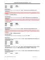
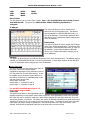
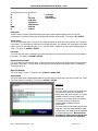
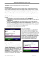
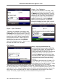
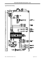
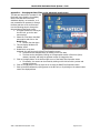
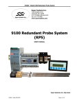
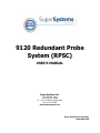
9120 Redundant Probe
System (RPSC)
USER’S MANUAL
Super Systems Inc.
7205 Edington Drive
Cincinnati, OH 45249
Ph : 513-772-0060, 800-666-4330
Fax: 513-772-9466
www.supersystems.com
Super Systems Inc. help desk:
1-800-666-4330
Model 9120 Redundant Probe System - Color
Table of Contents
TABLE OF CONTENTS ................................................................................................................................................. 2
SAFETY ...................................................................................................................................................................... 3
9120 WIRING TERMINALS .......................................................................................................................................... 4
ABOUT THE MODEL 9120 – RPS ................................................................................................................................. 5
ELECTRICAL INSTALLATION ........................................................................................................................................ 5
MODEL 9120-RPS FUNCTION ..................................................................................................................................... 5
MAIN OVERVIEW SCREEN .......................................................................................................................................... 6
MENU SCREENS ......................................................................................................................................................... 8
SHUT DOWN INTERFACE ...................................................................................................................................................... 9
RELAY ASSIGNMENTS ......................................................................................................................................................... 9
REDUNDANT PROBE SETUP ................................................................................................................................................. 9
COMMUNICATIONS SETUP ................................................................................................................................................ 10
ANALOG INPUT SETUP ...................................................................................................................................................... 12
CALIBRATION .................................................................................................................................................................. 13
Overview ................................................................................................................................................................. 13
Equipment needed.................................................................................................................................................. 14
Calibration Procedure ............................................................................................................................................. 14
Input - Zero Calibration........................................................................................................................................... 14
Input – Span Calibration ......................................................................................................................................... 14
Output – Zero Calibration ....................................................................................................................................... 15
Output – Span Calibration ...................................................................................................................................... 15
Cold Junction .......................................................................................................................................................... 15
CONFIGURATION ............................................................................................................................................................. 16
Compact Database ................................................................................................................................................. 16
Communications Setup ........................................................................................................................................... 16
Read/Write Data .................................................................................................................................................... 16
Edit Trend Charts .................................................................................................................................................... 16
Return ..................................................................................................................................................................... 17
CHART SCREEN ........................................................................................................................................................ 18
CHART MENU ................................................................................................................................................................. 18
TYPICAL ELECTRICAL DRAWING ............................................................................................................................... 20
APPENDIX 1 – CHANGING THE DATE/TIME ON THE ADVANTECH TOUCH SCREEN ................................................... 22
REVISION HISTORY .................................................................................................................................................. 23
4580 – Redundant Probe System – Color
Page 2 of 23
Model 9120 Redundant Probe System - Color
Safety
•
Safety Symbols - Various symbols are used on the instrument. They have the following meaning:
!
Caution (refer to the accompanying documents)
•
Grounding of the temperature sensor shield - In some installations, it is common practice to replace the
temperature sensor while the controller is still powered up. Under these conditions, as additional
protection against electric shock, it is recommended that the shield of the temperature sensor be
grounded. Do not rely on grounding through the framework of the machine.
•
Installation requirements for EMC - To ensure compliance with the European EMC directive, certain
installation precautions are necessary. When using relay or triac outputs, it may be necessary to fit a
filter suitable for suppressing the emissions. The filter requirements will depend on the type of load. For
typical applications, it is recommended to use Schaffner FN321 or FN612.
•
Routing of wires - The wiring for the low voltage DC, and particularly the sensor, input should be
routed away from high-current power cables. This will minimize the pick-up of electrical noise. When it
is impractical to do this, use shielded cables with the shield grounded at one end.
4580 – Redundant Probe System – Color
Page 3 of 23
Model 9120 Redundant Probe System - Color
9120 Wiring Terminals
4580 – Redundant Probe System – Color
Page 4 of 23
Model 9120 Redundant Probe System - Color
About the Model 9120 – RPS
The Model 9120-RPS is specifically designed to read two SSi Gold Probes, installed in the same furnace.
The Model 9120-RPS controller, a 24 VDC power supply, and two 24 VDC relays are mounted and wired on
a piece of DIN rail for easy mounting. Two other components included with the Model 9120-RPS are the
operator interface and the cable connecting the operator interface to the Model 9120-RPS.
Electrical Installation
The Model 9120-RPS comes mounted on a DIN rail, pre-wired and tested. AC power needs to be connected
to the 24VDC power supply. See the section Typical Electrical Drawing for other required connections.
Model 9120-RPS Function
The Model 9120-RPS reads a signal from each of the two oxygen probes located in the furnace. Depending
on the 9120-RPS configuration, it will select whichever millivolt reading it has been configured (high or low)
to select and retransmit this millivolt output to the atmosphere controller.
The probe millivolt deviation band and the alarm delay times are set using the operator interface. See the
section Menu Screens and Chart Screen for more information on how to use the operator interface. When
connected per the electrical drawing (section Typical Electrical Drawing), the Model 9120-RPS default
configuration is set to retransmit the millivolt signal from the probe with the highest millivolt output. As
time passes and if/when the other probe’s millivolt output becomes greater (dependent on the deviation
band), the Model 9120-RPS will switch the output from one probe to the other and send the “new” higher
(or lower, depending on the configuration) millivolt signal to the atmosphere controller. The deviation band
must be exceeded for the retransmit to occur.
The black millivolt value on the operator interface display indicates which probe’s millivolts are being used
by the furnace atmosphere controller.
The operator can manually select the probe that is to be used in the carbon calculation. If this feature is
used, the 9120-RPS will use the operator-selected probe, and NOT switch from one probe to the other
automatically. See the section Menu Screens – Redundant Probe Setup for more information on how to
manually select a probe.
The deviation alarm is disabled if both probes’ millivolts drop below 950. This should eliminate the nuisance
alarm when the furnace is loaded and the temperature drops.
4580 – Redundant Probe System – Color
Page 5 of 23
Model 9120 Redundant Probe System - Color
Using the operator interface shown below you can configure the Model 9120-RPS per these instructions
Main Overview Screen
The Main Overview screen will be the initial screen that is displayed when the RPS is first started up. The
Main Overview screen will display: the two probes’ millivolts values, as well as the Menu button and the
Chart button. The active probe will be displayed in Black, while the inactive probe will be displayed in
Gray. Any activated output will be lit up on the RPS unit. Any error or message will be displayed above the
Menu and Chart buttons.
The list of runtime messages is:
• Probe n active – indicates which probe is selected. This message may be followed by:
o Selection n forced by digital input – Indicates that the selected probe has been forced
by digital input. Digital input 1 selects probe 1; input 2 selects probe 2.
o User controlled – Indicates that the probe has been manually selected by the operator.
o Out of band condition detected – Indicates that the current probe has just gone out of
band
o Changing to probe n in mm minutes ss seconds – Indicates that the specified probe
will be selected in the time frame provided. The message will count down while the timer
is active.
The list of error conditions is:
• Both inputs less than 950 mV – Neither probe can be selected when both inputs are less than
950 mV.
• Input n over 1300 mV – The indicated input is over range.
4580 – Redundant Probe System – Color
Page 6 of 23
Model 9120 Redundant Probe System - Color
Both inputs over 1300 mV – Both inputs are over range.
Probe Deviation – The selected alarm is active. See the alarms section for instructions on setting
up the alarms.
The Menu button will display the menu options that will allow the user to configure the RPS unit. The
Chart button will display the chart screen. See the Menus Screens and Chart Screen sections for
instructions on the menus and the Chart Screen.
•
•
4580 – Redundant Probe System – Color
Page 7 of 23
Model 9120 Redundant Probe System - Color
Menu Screens
The menu screen will allow the user to configure
the RPS unit, based on the login level. When the
menu list is first displayed, the user will be
automatically logged in at the Operator-level.
The number of menus will vary based on the
login level. The default login for Supervisor is a
1. The default login for Administrator is 2. The
Operator –level will have the following menu
items:
• Shut down interface
The Supervisor-level will have the following
menu items:
• Shut down interface
• Relay Assignments
• Redundant Probe Setup
The Administrator-level will have the following
items:
• Shut down interface
• Relay Assignments
• Redundant Probe Setup
• Communications Setup
• Analog Input Setup
• Calibration
• Configuration
There is also an SSi-special-level that can only be
accessed with the passcode that can be provided
by Super Systems Inc at 800-666-4330.
Currently, the menu list for this level is the same
as the list for the Administrator-level. To select a
menu item, highlight the item by clicking on it
and pressing the Detail button.
4580 – Redundant Probe System – Color
Page 8 of 23
Model 9120 Redundant Probe System - Color
Shut down interface
This option will shut down the RPS unit interface. This option can be
used before turning off the power to the RPS unit to verify that all the
information has been saved. The user will need to verify the
shutdown process. Once the interface has been shut down, it can be
restored simply by cycling power to the unit, or by pressing the
reboot button on the screen.
Relay Assignments
This screen will display a description of the eight
relay assignments. The eight “Outputs” on the
front of the unit represent the eight relay
assignments, where Output #1 = Relay
Assignment 1, etc. Most of the relays in the RPS
are not used. All of the relay assignments are
fixed in the RPS. Relay 5 is the probe select relay.
Relay 7 is the probe deviation alarm.
Redundant Probe Setup
This menu option will allow the user to configure
the RPS setup.
Alarm band (mV)
This is the millivolt difference that must be observed for
the RPS to change probes. For example, when the RPS
is selecting the highest probe with probe 1 as 1055 mV
and a band of 20 mV, and if probe 2 hits 1076 mV, the
RPS will start counting down the Alarm Delay timer
(below). When the delay times out, probe 2 would be
selected. If probe 2 comes back in band (drops to
1075), the timers starts over again. The range is 0 to
600.
Alarm delay (min)
The number of minutes that the RPS waits to activate
4580 – Redundant Probe System – Color
Page 9 of 23
Model 9120 Redundant Probe System - Color
the alarm relay and switch probes when an out-of-band condition is detected. Note - There is a 950 mV
low limit for an alarm. This condition is typically found during a burnoff, so the alarm will not
be active when the input drops below 950 mV.
The range is 0 to 9999.
Selected Probe
Indicates which probe is selected. Note – This field is only editable when the Probe select mode
(below) is set to no auto switch. The options are: 1 or 2.
Probe select mode
This determines how the specified probe is selected. The options are: highest mV, lowest mV, or no
auto switch (manual mode).
Communications Setup
This menu option will allow the user to configure
the communications settings for the RPS unit.
Note – It is strongly recommended that
none of these settings be modified without
assistance from Super Systems at 800666-4330.
RS-232B Baud
This will allow the user to set the RS-232B baud
rate. Note – This must be set to 19200 for
the Touchscreen.
If the Baud rate is switched, the screen
will no longer communicate with the
instrument, and the RPS unit will need to
be returned to Super Systems, Inc for
repair. The Baud rate should be fixed at
19200.
The options are:
1200
14400
57600
2400
19200
76800
4800
28800
115200
9600
38400
RS232B Mode
This will allow the user to set the RS232B mode. Note – This must be set to Modbus for the
Touchscreen.
If the Mode is switched, the screen will no longer communicate with the instrument, and the
RPS unit will need to be returned to Super Systems, Inc for repair. The Mode should be fixed
at Modbus.
The options are: Modbus master or Modbus.
RS-232A Baud
This will allow the user to set the RS-232A baud rate. Note – This must be set to 19200 for the
Touchscreen.
If the Baud rate is switched, the screen will no longer communicate with the instrument, and
the RPS unit will need to be returned to Super Systems, Inc for repair. The Baud rate should
be fixed at 19200.
The options are:
1200
14400
57600
4580 – Redundant Probe System – Color
Page 10 of 23
Model 9120 Redundant Probe System - Color
2400
4800
9600
19200
28800
38400
76800
115200
RS232A Mode
This will allow the user to set the RS232A mode. Note – This must be set to Modbus for the
Touchscreen.
If the Mode is switched, the screen will no longer communicate with the instrument, and the
RPS unit will need to be returned to Super Systems, Inc for repair. The Mode should be fixed
at Modbus.
The options are: Modbus, H2 cell.
Host 485 Baud
This will allow the user to set the Host 485 baud rate. Note – This must be set to 19200 for the
Touchscreen.
If the Baud rate is switched, the screen will no longer communicate with the instrument, and
the RPS unit will need to be returned to Super Systems, Inc for repair. The Baud rate should
be fixed at 19200.
The options are:
1200
14400
57600
2400
19200
76800
4800
28800
115200
9600
38400
Host 485 Mode
This will allow the user to set the Host 485 mode. Note – This must be set to Modbus for the
Touchscreen.
If the Mode is switched, the screen will no longer communicate with the instrument, and the
RPS unit will need to be returned to Super Systems, Inc for repair. The Mode should be fixed
at Modbus.
The options are: MMI, or Modbus selectable.
Host 485 Address
This will allow the user to set the Host 485 address. The range is 0 to 249.
Slave 1 Baud
This will allow the user to set the Slave 1 baud rate. Note – This is configurable, but currently, it is
not used with the RPS.
The options are:
1200
14400
57600
2400
19200
76800
4800
28800
115200
9600
38400
Slave 1 Mode
This will allow the user to set the Slave 1 mode. Note – This is configurable, but currently, it is not
used with the RPS The options are: MMI, Modbus master, Yokogawa, or Modbus host.
Slave 2 Baud
This will allow the user to set the Slave 2 baud rate. Note – This is configurable, but currently, it is
not used with the RPS
The options are:
1200
14400
4580 – Redundant Probe System – Color
57600
Page 11 of 23
Model 9120 Redundant Probe System - Color
2400
4800
9600
19200
28800
38400
76800
115200
Slave 2 Mode
This will allow the user to set the Slave 2 mode. Note – This is configurable, but currently, it is not
used with the RPS. The options are: MMI, Modbus, ADAM, SSi Analog Input Board, or
Yokogawa.
IP Address
This option will allow the user to modify the IP
address of the 9120 Instrument only. The address
must be supplied in a 999.999.999.999 format, or it
will not be accepted. Contact Super Systems at 800666-4330 or your IT department before changing any
of the IP addresses.
Subnet Mask
This option will allow the user to modify the IP subnet
mask of the 9120 Instrument only. The address must
be supplied in a 999.999.999.999 format, or it will not
be accepted. Contact Super Systems at 800-6664330 or your IT department before changing any of
the IP addresses.
Gateway
This option will allow the user to modify the IP gateway of the 9120 Instrument only. The address must be
supplied in a 999.999.999.999 format, or it will not be accepted. Contact Super Systems at 800-666-4330
or your IT department before changing any of the IP addresses.
Analog Input Setup
The 9120 controller has two analog inputs. Each of
the inputs comes with a factory default
configuration dependent on the application (refer to
PVT type under the Furnace Setup section). It can
be modified prior to shipment to your facility or in
the field by a technician or qualified/trained person
with the proper security code.
Analog Input Terminals
Analog Input 1 – terminals 31 and 32
Analog Input 2 – terminals 29 and 30
For the RPS, the default input type is 2.5
Volts, with a range of 2500.
Input Type
The thermocouple type for most applications can be
modified depending on your specific needs. Please note that in some applications, some of the inputs DO
NOT allow the user to modify the Input type. Note: Before changing the input type, make sure to set the
appropriate jumpers, if necessary. The jumper will need to be manually changed on the input board before
changing the input type to a 10:1 setting (non-thermocouple types). To change the Input type, first select
which input you want to change by selecting it in the pull-down menu at the top of the screen. Once
selected, click OK and the displayed Input type under Value will be the current type.
4580 – Redundant Probe System – Color
Page 12 of 23
Model 9120 Redundant Probe System - Color
The following is a list of the options:
B
S
C
T
E
2.5 volts
J
1.28 volts
K
78.125 mV
N
19.53125 mV
NNM
4-20 mA
R
25 volts
12.5 volts
781.25mv
195.3125 mV
Filter time
The filter time is a factory applied averaging tool used to help maintain steady control in high EMI
environments. The filter time should not be adjusted without consulting SSI. The range is 0 to 32767.
Initial Scale
This is the initial scale value. Clicking on this value will display an input box from which the user can select
a new value. This could also be referred to as the starting value. For example, the initial value is the value
when 0 volts is on the selected input; or on a 4-20 mA input, it would be the value at the selected input of
4 mA. The range is –32768 to 32767.
Full scale
This is the full scale value. Clicking on this value will display an input box from which the user can select a
new value. The range is –32768 to 32767.
Decimal Point Location
This is the decimal point location value. Clicking on this value will display an input box from which the user
can select a new value. This will affect the PV value and the location of the decimal when it is displayed.
The range is 0 to 4.
Open TC behavior
This is the open TC value. The options are: up scale or down scale.
Input Offset
The input offset value is algebraically added to the input value to adjust the input curve on read-out. Note:
The input offsets are unscaled. The range is –32767 to 32767.
Calibration
Overview
The series 9120 controller can be calibrated
using the touch screen and a calibrator.
Before performing this procedure on a newly
installed controller, the unit needs to be
powered on for at least thirty (30) minutes
for a warm up period to allow the
inputs/outputs to stabilize with the
environment.
The series 9120 has two analog inputs. Each
range has a zero and span calibration value.
A cold junction trim value must be calibrated
for thermocouple inputs. Note: the cold
junction trim value must be performed,
if necessary, after the zero and span
4580 – Redundant Probe System – Color
Page 13 of 23
Model 9120 Redundant Probe System - Color
calibration. There are two analog outputs each with a zero and span value.
Equipment needed
A certified calibrator(s) with the ability to source and measure millivolts, milliamps and thermocouples is
required. The appropriate connection leads are also required. A 24VDC 75-watt power supply is required.
The operator interface method requires a PC with the Configurator software loaded. An Ethernet crossover
cable is required. It is important to note that when performing a zero or span calibration, do not use
regular thermocouple wiring. Instead, use any kind of regular sensor wire, or even regular copper wire.
To perform the calibrations, the user will need a calibrator that is capable of sourcing volts, millivolts, and
temperature.
Calibration Procedure
The calibration procedure for an input or output will be the same regardless of which operation is being
performed.
1. Zero Input: Source a zero mV value to the terminals. Press the Calibrate button.
2. Span Input: Source a specific mV value to the terminals and enter the value in the box. Press the
Calibrate button.
3. Zero Output: Press the Ready button, which will set the output to 0%, or 4 mA. Measure the
current at the terminals and input the measured value. In the number box, use the arrows or tap
the box to enter the value with the key pad. Press the Calibrate button.
4. Span Output: Press the Ready button, which will set the output to 100%, or 20 mA. Measure the
current at the terminals and input the measured value. In the box, use the arrows or tap the box
to enter the value with the key pad. Press the Calibrate button.
5. Cold Junction Trim: Enter the temperature of the input.
Input - Zero Calibration
To perform a zero calibration on an input, verify that
the “Zero” option at the top is selected. Select the
target millivolts that will be sourced. Note – For a
zero calibration, it is recommended that 0 mV be
sourced. The recommended millivolt source value will
be displayed as well. The mV value will be displayed
on the screen. Press the Calibrate button to begin
the calibration. The calibration status will be displayed
on screen. When it is over, the screen will display
“idle” once again. Once the zero calibration has
finished, the span calibration can be performed.
Input – Span Calibration
To perform a span calibration on an input, verify that
the “Span” option at the top is selected. Select the
target millivolts that will be sourced. Note – For a
span calibration, it is recommended that 90 %
of the full range be sourced. The recommended
millivolt source value will be displayed as well. The
mV value will be displayed on the screen. Press the
Calibrate button to begin the calibration. The
calibration status will be displayed on screen. When it
is over, the screen will display “idle” once again.
4580 – Redundant Probe System – Color
Page 14 of 23
Model 9120 Redundant Probe System - Color
Output – Zero Calibration
To perform a zero calibration on an output, verify
that the “Zero” option at the top is selected. Press
the Ready button to begin the process. Enter the
mA value that is being measured at the appropriate
terminals (see the 9120 Wiring Terminals section;
the appropriate terminals to measure will also be
displayed on the screen). Press the Calibrate
button to finish the calibration. The calibration
status will be displayed on screen. When it is over,
the screen will display “idle” once again. Once the
zero calibration has finished, the span calibration can
be performed.
Output – Span Calibration
To perform a zero calibration on an output, verify
that the “Span” option at the top is selected. Press
the Ready button to begin the process. Enter the
mA value that is being measured at the appropriate
terminals (see the 9120 Wiring Terminals section;
the appropriate terminals to measure will also be
displayed on the screen). Press the Calibrate
button to finish the calibration. The calibration
status will be displayed on screen. When it is over,
the screen will display “idle” once again.
Cold Junction
Note – The cold junction should be
performed after any zero/span calibration.
To perform a cold junction, the corresponding T/C
wire will need to be setup on the inputs. A
specific temperature will need to be sourced to the
selected input. Return to the main screen by
pressing the Return button three times to read
the input’s PV value. Mark down the displayed PV
value and determine the difference between the
displayed PV value and the value that is being
sourced.
For example, assume that input 3 is setup for T/C
type K, and 1000 ◦F is being sourced in. On the
main display, the PV for input 3 is 1002 ◦F. Return
to the Cold Junction menu under the Calibration menu. The value displayed on the Cold Junction
Calibration screen is the current temperature of the terminals. Assume this value is 95.5 ◦F. In the number
box, the user would enter a -2 degree difference, or 93.5 ◦F, since the temperature sourced (1000 ◦F) – PV
value (1002 ◦F) = -2 ◦F. Press the Calibrate button to finish off the cold junction calibration. Return to the
main screen to see if the selected input’s PV value is now displaying the correct value of what is being
sourced. If necessary, repeat these steps to further calibrate the cold junction value.
4580 – Redundant Probe System – Color
Page 15 of 23
Model 9120 Redundant Probe System - Color
Configuration
The Configuration menu will allow the user to set up some
configurations for the Touchscreen. Currently, there are
five buttons on the screen: Compact Database,
Communications Setup, Read/Write Data, Edit
Trend Charts, and Return.
Compact Database
This option will compact the database. The database
stores alarm and event records, as well as some basic
administration data for the RPS. An hourglass will appear
on the screen while the database is being compacted.
Communications Setup
The communications setup screen will allow the user
to configure how the touch screen will communicate
with the 9120 instrument. The “Media” drop-down list
will set the communications media (COM ports or
Ethernet). The options are: COM1, COM2, COM3,
COM4, or Ethernet.
The “Address” box will set the address to use. The
range is 1 to 255.
The “Baud” drop-down list will set the baud rate to
use for communications. The options are:
1200
14400
57600
2400
19200
76800
4800
28800
115200
9600
38400
Read/Write Data
This option will allow the user to view the data
log data registers directly. This can be helpful
during troubleshooting issues. This option can
only be accessed with the SSi special-level
passcode. Contact Super Systems at 800-6664330 to obtain the special-level passcode. The
screen will display one-hundred registers at a
time, starting at register 0. To change the
starting register, use the up/down arrows on
the top number box, or use the numeric
keypad that pops up and enter the new
register. The range for the top number box is
0 to 32000. Values can also be written to the
registers by using the two bottom number
boxes. The “Write offset” number box will set
the register to write, and the “Write value”
number box will set the value to write back to
the register. Click on the Write button to write the value.
Edit Trend Charts
This menu option will allow the user to modify a trend chart. Any added trend lines will be displayed on the
Chart screen. The buttons on the top of the screen will work with the trend chart file itself:
4580 – Redundant Probe System – Color
Page 16 of 23
Model 9120 Redundant Probe System - Color
Open – Open an existing trend chart
Delete – Delete an existing trend chart
Save – Save any changes made to the
current trend chart
• Save As – Save the current trend chart
as a new trend chart
Open and Delete will display a screen where
the user can select the trend chart to open or
delete. Save will automatically save the
changes to the currently opened trend chart.
Save As will let the user enter the name of the
new trend chart.
The three buttons below the list of trend items
will allow the user to modify individual trend
items:
• Add – Add a new trend line to the trend
chart
•
•
•
Edit – Edit an existing trend line in the trend
chart
• Delete – Delete an existing trend line in the
trend chart
Add and Edit will display a screen (shown) where the
user can set up the trend line. Delete will delete the
selected trend line from the trend chart.
• Name – This is the name of the trend line.
•
Note – since space is limited, it is
suggested that the trend lines be named
with least understood characters, i.e., “Prb
1” instead of “Probe 1”
•
•
•
•
•
•
•
•
Press
Data – This is the data from the data log data.
Descriptions are used to make the selection of
data easier. If no description is provided, the register number is provided
Min – This is the minimum value for the scale of the data
Max – This is the maximum value for the scale of the data
Expression – The expression to display the data with the correct scaling. Data in the registers
does not have any scale. For instance, T/C data will require the “x*0.1” expression to display the
T/C values properly. Trend lines that do not require any scaling will just need an “x” as the
expression. Probe values do not need scaling
Format - the value displayed on the chart display of the operator interface. A short custom
description can be added here. For example, to display one (1) decimal point, enter a value of
“#0.0”. For carbon values, enter a value of “#0.00” for 2 decimals. This would display a value
like “0.81”. Entering “#.00” would display a value of “.81”
Units – The type of units to be displayed
Line Width - A numeric value for the thickness of the trend line. A 1 is a thin line; A higher value
= thicker line width
Sample – This will allow the user to test the expression to verify that the expression is set up
properly. Enter the test value and press the Test button to see if the expression displays the value
properly. For instance, if the “x*0.1” expression is used and “1500” is entered, then the result
would display “150”
the Set button to confirm the changes made. Pressing the Cancel button will not set any changes.
Return
This option will return the user to the Menu screen.
4580 – Redundant Probe System – Color
Page 17 of 23
Model 9120 Redundant Probe System - Color
Chart Screen
The Chart Screen will display the trend lines for the selected trend chart. The chart can be viewed either in
real-time mode, or in historical mode. The left side of the screen will display the selected trend line’s
scaling, as set up in the Edit Trend Chart section of the Configuration menu. A trend line’s scaling, name,
and data will all be in the same color for ease of viewing. Pressing the scale bar will allow the user to cycle
through the available trend scales. Even though multiple trend lines will have different scales, the lines will
all be displayed on the same screen. The trend chart’s name will be displayed at the top of the screen.
The red vertical line is the chart’s cursor. In realtime mode, the cursor is at the far right of the screen.
The cursor can be moved by pressing on it and moving it left or right. Moving the cursor will display the
trend values for the selected time. The chart can also be panned by pressing the green arrows to move
forward or backward by the selected sample rate – 2 hours, 4 hours, etc. Pressing the trend names that
are on top of the menu buttons will enable or disable the trend lines on the chart. This is useful if the user
wishes to only view one or two trend lines on the chart. Disabled trend names will be in gray.
Chart Menu
The chart menu button will display more options for the displayed data. Note – The Chart Menu can also
be displayed by pressing on the chart area for a couple of seconds. The options are:
• Realtime
• Sample
• ZOOM
• Note
• Jump
• Statistics
• Exit
4580 – Redundant Probe System – Color
Page 18 of 23
Model 9120 Redundant Probe System - Color
Realtime – Selecting this option will set the chart back in realtime mode
Sample – This will set the sample rate of the chart. The options are:
30 Minutes
1 hour
2 hours
4 hours
8 hours
12 hours
1 day
2 days
7 days
ZOOM – This will allow the user to zoom in on a specific area of the chart. When in ZOOM mode, the
word “ZOOM” will be visible in the middle of the chart. The user can zoom by using the stylus or a finger
on the screen to create a box around the desired area of the chart. The zoom box will also display decimal
values for the low and high variables inside the box. It will also display the start and end time for the zoom
box itself. The zoom feature can be used as often as desired allowing the user to drill down on the variable
to show a specific value displayed on the screen. This is similar to the Zoom feature on SSi’s SD Recorder
application. Note – When in ZOOM mode, the Restore button will become visible. Restore will
restore the chart to its original dimensions.
Note – This will allow the user to enter a note on the chart at the cursor’s location. The user can enter a
note either with a stylus or with the onscreen keyboard. Note – When using the stylus, it is better to
move slowly. Moving quicker may not pick up the entire entered note. A note icon will be
displayed on the chart at the location of the note. Clicking on the icon will display the note.
Jump – the Jump feature allows the operator to select a date and time for variables to be displayed.
Choose a date from the calendar, then press the right or left arrow keys in the time display for the time
desired. Press OK to set the screen to the selected date and time.
Statistics - Choosing this option allows the operator to view statistics on any variable displayed on the
touch screen. The statistics are based on the screen image displayed whether looking at seven days of
data or zoomed in on a few minutes. The statistics will display:
Name of the trend line
Minimum value of the trend line
Maximum value of the trend line
The number of data points
The average value of the trend line
The standard deviation of the values
Exit – This will hide the chart menu.
4580 – Redundant Probe System – Color
Page 19 of 23
Model 9120 Redundant Probe System - Color
Typical Electrical Drawing
1
2
3
4
5
6
7
8
9 10 11 12 13 14 15 16
PORT A
PORT B
FEMALE
MALE
MODEL
S/N
17 18 19 20 21 22 23 24 25 26 27 28 29 30 31 32
4580 – Redundant Probe System – Color
Page 20 of 23
Model 9120 Redundant Probe System - Color
Spare Parts:
Description
Power Supply
Gold Probes
4580 – Redundant Probe System – Color
Part Number
31135
Check the current part number of your SSi Probe
Page 21 of 23
Model 9120 Redundant Probe System - Color
Appendix 1 – Changing the Date/Time on the Advantech touch screen
The date and time that is recorded on the
flash card (and, therefore, the datalog
data) is the date and time of the
Advantech display, not controller, so it
may sometimes be necessary to change
the date and time of the touch screen.
Use the following steps to change the
date and time of the touch screen:
1. If the RPS software is running on
the RPS unit, go to the main
menu system
2. Select the “Shut down interface”
menu option and click on the
Detail button.
a. Confirm the shut down
3. This will display Windows CE
desktop screen
4. Double-click on the time
displayed; this will bring up the Date/Time Properties screen.
a. The date can be changed simply by clicking on the new date
b. The time can be changed by clicking on the appropriate section of the time (hours,
minutes, seconds) and using the up/down arrows to change the time
5. Click on the Apply button in the bottom right corner of the Date/Time Properties screen
a. If necessary, the screen can be moved by clicking on the title bar with a pointer and
moving the pointer
6. Click on the OK button in the top right corner to close the Date/Time Properties screen
7. Start up the RPS software by cycling power to the RPS unit, or by clicking on the reboot button
next to the displayed time
4580 – Redundant Probe System – Color
Page 22 of 23
Model 9120 Redundant Probe System - Color
Revision History
Rev.
-
Description
4580 – Redundant Probe System – Color
Initial Release
Date
04-28-2009
MCO #
N/A
Page 23 of 23