1
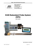
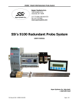
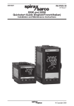
M4560 - Model 9120 Redundant Probe System
P/N 13362
9120 Redundant Probe
System (RPS)
USER’S MANUAL
Super Systems Inc.
7205 Edington Drive
Cincinnati, OH 45249
513-772-0060, 800-666-4330
Fax: 513-772-9466
www.supersystems.com
Super Systems Inc. help desk:
1-800-666-4330
M4560 - Model 9120 RPS
Page 1 of 11
M4560 - Model 9120 Redundant Probe System
Table of Contents:
Table of Contents: ...............................................................................................................................2
Safety: ...............................................................................................................................................3
Wiring Terminals .................................................................................................................................4
9120 Wiring Terminations ....................................................................................................................4
About the Model 9120 – RPS: ...............................................................................................................5
Electrical Installation:...........................................................................................................................5
Model 9120-RPS Function: ...................................................................................................................5
Configuration ......................................................................................................................................6
Configuration – Deviation Band.............................................................................................................6
Configuration – Alarm Delay .................................................................................................................7
Configuration – Probe (Prb) Select Mode ...............................................................................................7
Configuration – Manual Probe (Prb) Select .............................................................................................7
Typical Electrical Drawing: ...................................................................................................................9
Spare Parts: ...................................................................................................................................... 10
Revision History: ............................................................................................................................... 11
M4560 - Model 9120 RPS
Page 2 of 11
M4560 - Model 9120 Redundant Probe System
Safety:
•
Safety Symbols - Various symbols are used on the instrument. They have the following meaning:
!
Caution (refer to the accompanying documents)
•
Grounding of the temperature sensor shield - In some installations, it is common practice to replace the
•
Installation requirements for EMC - To ensure compliance with the European EMC directive, certain
installation precautions are necessary. When using relay or triac outputs, it may be necessary to fit a
filter suitable for suppressing the emissions. The filter requirements will depend on the type of load. For
typical applications, it is recommended to use Schaffner FN321 or FN612.
•
Routing of wires - The wiring for the low voltage DC, and particularly the sensor, input should be
routed away from high-current power cables. This will minimize the pick-up of electrical noise. When it
is impractical to do this, use shielded cables with the shield grounded at one end.
temperature sensor while the controller is still powered up. Under these conditions, as additional
protection against electric shock, it is recommend that the shield of the temperature sensor be
grounded. Do not rely on grounding through the framework of the machine.
M4560 - Model 9120 RPS
Page 3 of 11
M4560 - Model 9120 Redundant Probe System
Wiring Terminals
9120 Wiring Terminations
M4560 - Model 9120 RPS
Page 4 of 11
M4560 - Model 9120 Redundant Probe System
About the Model 9120 – RPS:
The Model 9120-RPS is specifically designed to read two SSi Gold Probes, installed in the same furnace.
The Model 9120-RPS controller, a 24 VDC power supply, and two 24 VDC relays are mounted and wired on
a piece of DIN rail for easy mounting by the customer. Two other components included with the Model
9120-RPS are the operator interface and the cable connecting the operator interface to the Model 9120RPS.
Electrical Installation:
The Model 9120-RPS comes mounted on a DIN rail, pre-wired and tested. AC power needs to be connected
to the 24VDC power supply. See the section Typical Electrical Drawing for other required connections.
Model 9120-RPS Function:
The Model 9120-RPS reads a signal from each of the two oxygen probes located in the furnace. Depending
on the 9120-RPS configuration, it will select whichever millivolt reading it has been configured to select and
retransmit this millivolt output to the atmosphere controller.
The probe millivolt deviation band and the alarm delay times are set using the operator interface. See the
section Configuration for more information on how to use the operator interface. When connected per the
electrical drawing (section Typical Electrical Drawing), the Model 9120-RPS default configuration is set to
retransmit the millivolt signal from the probe with the highest millivolt output. As time passes and if/when
the other probe’s millivolt output becomes greater (dependent on the deviation band), the Model 9120-RPS
will switch the output from one probe to the other and send the “new” higher (or lower, depending on the
configuration) millivolt signal to the atmosphere controller. The deviation band must be exceeded for the
retransmit to occur.
The asterisk (*) on the operator interface display indicates which probe’s millivolts are being used by the
furnace atmosphere controller. When the Model 9120-RPS switches the output from one probe to the other
it indicates a deviation band alarm condition, flashing an A on the operator interface. The red light in the
upper left corner of the operator interface will be lit as well in an alarm condition. The A continues to flash
until the probe’s output is back within the deviation band.
The operator can manually select the probe that is to be used in the carbon calculation. If this feature is
used, the 9120-RPS will use the operator-selected probe, and NOT switch from one probe to the other
automatically. See the section Configuration – Probe (Prb) Select Mode for more information on how to
manually select a probe.
The deviation alarm is disabled if both probes’ millivolts drop below 950. This should eliminate the nuisance
alarm when the furnace is loaded and the temperature drops.
M4560 - Model 9120 RPS
Page 5 of 11
M4560 - Model 9120 Redundant Probe System
Using the operator interface shown below you can configure the Model 9120-RPS per these instructions
Configuration
With the initial display screen showing (as in the picture above), pressing the ENT key takes you to the
second menu item in the Model 9120, Deviation Band Menu. Pressing the NEXT key takes you to the third
menu item, Alarm Delay Menu. Pressing the NEXT key again takes you to the fourth menu item, Probe
(Prb) Select Mode. Pressing the NEXT key again takes you to the fifth menu item, Manual Probe (Prb)
Select Menu. Pressing the NEXT key again will display the initial display screen.
From the initial display, pressing the NEXT key instead of the ENT key will display the 800 number for
Super Systems Inc. Pressing the NEXT key again will display the address information for Super Systems
Inc. Pressing the NEXT key again will display the initial display.
Note about configuration – values are entered from left to right on the display. For example, to enter the
number 15, the user would press the up arrow key once so that a 1 is displayed. The user would then
press the left arrow key once so that a 10 is displayed. Next, the user would press the up arrow key five
times so that a 15 is displayed. The number that will be modified will always flash on the display.
Configuration – Deviation Band
The Deviation Band menu screen will display the number of millivolts that the deviation band alarm is set
for (default = 10 mV). Pressing the ENT key will enable the user to modify the deviation band value. Once
the ENT key is pressed, the rightmost number will begin flashing. Pressing the up arrow key will reset the
value to a 1. Pressing the up arrow key again will increment this value by one. Enter the new value as
desired. Pressing the ENT key will set the entered value. Pressing the CLR key will reset the value to the
last set value. Pressing the NEXT key will display the Alarm Delay menu screen. Pressing the PREV key
will display the initial display.
Example - The following example will show how to set the deviation band from a value of 50 mV to a
value of 35 mV. Press the ENT key. The 0 in the 50 will begin flashing. Press the up arrow key three
times so that a 3 is displayed. Press the left arrow key once so that a 30 is displayed. Press the up arrow
key five times so that a 35 is displayed. Press the ENT key to set the value. Note about Deviation Band –
the valid range of values for the deviation band is 0 to 50 mV. Any value entered over 50 mV will be set to
the last set value by default.
M4560 - Model 9120 RPS
Page 6 of 11
M4560 - Model 9120 Redundant Probe System
Configuration – Alarm Delay
The Alarm Delay menu screen will display the number of minutes that an alarm can be delayed before
switching the probe output from one probe to the other (default = 20 minutes). To change the value,
press the ENT key. The rightmost digit will begin flashing. Pressing the CLR key will display the value as
0. Pressing the up arrow key once will display the value as 1. Pressing the up arrow key once again will
increment this value by one. Enter the new value as desired. Pressing the ENT key will set the entered
value. Pressing the NEXT key will display the Probe Select (Prb) Mode menu screen. Pressing the PREV
key will display the Deviation Band menu screen.
Note: There is a 950 mV low limit for an alarm. This condition is typically found during a burnoff, so the
alarm will not be active when the input drops below 950 mV.
Example – The following example will show how to set the alarm delay from a value of 5 min to a value of
10 min. Press the ENT key. The 5 will begin flashing. Press the up arrow key once so that a 1 is
displayed. Press the left arrow key once so that a 10 is displayed. Press the ENT key to set the value.
Note about Alarm Delay – the valid range of values for the alarm delay is 0 to 60 minutes. Any value
entered over 60 minutes will be set to the last set value by default.
Configuration – Probe (Prb) Select Mode
To select the probe that you want to use to establish the % Carbon on your carbon controller you can do
one of two things. One, a three-position selector switch can be installed as shown on the electrical
drawings (see Typical Electrical Drawing) -the left-position is Probe 1, the middle position is AUTO, and the
right-position is Probe 2. Two, press the ENT key. The default selection is 0 – Auto – Highest.
Once the ENT key has been pressed, the left digit will be flashing. This digit represents the mode for the
RPS unit. The possible digits/modes are:
0 – Auto – Highest *This will select the higher value when one of the probes goes out of band
1 – Auto – Lowest *This will select the lower value when one of the probes goes out of band
2 – Manual
*This option allows the user to manually select a probe to use.
Press the up arrow key for the desired option, then press the ENT key to set the value. Pressing the NEXT
key will display the Manual Probe (Prb) Select menu option. Pressing the PREV key will display the Alarm
Delay menu screen.
Example – The following example will show how to set the probe selection mode from a value of 0 (Auto –
Highest) to a value of 2 (Manual). Press the ENT key. The 0 on the left of the screen will begin
flashing. Press the up arrow key twice so that a 2 is displayed (The “Auto – Highest” will not be replaced
until the new mode has been set). Press the ENT key. The screen will now display 2 Manual. Note
about probe selection mode – Although the numbers will cycle from 0 to 9, the only valid values are 0, 1,
and 2. Any value higher than 2 will be set to the last set value by default.
Configuration – Manual Probe (Prb) Select
The Manual Probe Select menu option allows the user to select a specific probe to use. The probe selected
will override the automatically selected probe. If in AUTO mode, the system will continue to select the
configured probe when the deviation band is exceeded. To run continuously in MANUAL mode, you must
first select the MANUAL mode from the Probe Select Mode menu (described above). To select a specific
probe, press the ENT key. The right digit will begin to flash. Pressing the up arrow key will reset the value
to 1. Press the up arrow key until the desired probe is reached. Once the desired probe has been selected,
press the ENT key to set the value. Pressing the NEXT key will display the initial display screen. Pressing
the PREV key will display the Probe (Prb) Select Mode menu screen.
Example – The following example will show how to set the manual probe selection from a value of 1
(Probe 1) to a value of 2 (Probe 2). Press the ENT key. The 1 in Probe 1 will begin flashing. Press the
up arrow key twice so that Probe 2 is displayed. Press the ENT key to set the value. Note about Manual
M4560 - Model 9120 RPS
Page 7 of 11
M4560 - Model 9120 Redundant Probe System
Probe Selection – Although the numbers will cycle from 0 to 9, the only valid values are 1 and 2. Any
value entered higher than 2 will be set to the last set value by default.
M4560 - Model 9120 RPS
Page 8 of 11
M4560 - Model 9120 Redundant Probe System
Typical Electrical Drawing:
1
2
3
4
5
6
PORT A
7
8
9 10 11 12 13 14 15 16
PORT B
MODEL
S/N
17 18 19 20 21 22 23 24 25 26 27 28 29 30 31 32
M4560 - Model 9120 RPS
Page 9 of 11
M4560 - Model 9120 Redundant Probe System
Spare Parts:
Description
Power Supply
Gold Probes
M4560 - Model 9120 RPS
Part Number
31135
Check the current part number of your SSi Probe
Page 10 of 11
M4560 - Model 9120 Redundant Probe System
Revision History:
Rev.
A
B
Description
Initial Release
Changed 9100 references to 9120, updated relay
terminals, wiring diagrams, updated wiring diagrams,
updated alarms section
Page #7: Default alarm delay time needs to be changed
from 5 min. to 20 min.; The “Probe difference alarm is
energized…” note needs to be removed; Typical
electrical drawing modified; Added “MCO #” column to
“Revision History” section
M4560 - Model 9120 RPS
Date
07-28-2006
08-14-2007
MCO #
N/A
2047
01-26-2009
2073
Page 11 of 11