1
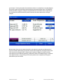
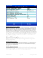
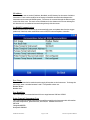
Operations Manual
PGA 3510
Portable 3-Gas IR
Analyzer
Please read, understand, and follow these instructions before operating this equipment.
Super Systems, Inc. is not responsible for damages incurred due to a failure to comply with
these instructions. If at any time there are questions regarding the proper use of this analyzer,
please contact us at (800) 666-4330 for assistance.
7205 Edington Drive
Cincinnati, OH 45249
513-772-0060 800-666-4330
Fax: 513-772-9466
www.supersystems.com
SSI Manual #4584 Rev. -
Page 1 of 20
PGA3510 Operations Manual
Table of Contents
Table of Contents................................................................................................................ 2
Introduction......................................................................................................................... 3
Specifications...................................................................................................................... 3
Basic Operating Description ............................................................................................... 4
Pump Operation .................................................................................................................. 5
Carbon Calculation ............................................................................................................. 5
Menu Lists .......................................................................................................................... 7
Sessions............................................................................................................................... 8
PUMP CONTROL............................................................................................................ 10
SENSOR CALIBRATION ............................................................................................... 11
Performing a Zero Calibration ...................................................................................... 12
Performing a Span Calibration...................................................................................... 12
Calibrating the Oxygen Sensor ..................................................................................... 12
Automatic Sampling Parameters....................................................................................... 13
Minimum Temperature for sampling............................................................................ 14
Minimum Millivolts for sampling ................................................................................ 14
Minimum Millivolt Condition… .................................................................................. 14
COF/PF Adjustment Increment .................................................................................... 14
COF/PF Adjustment Interval (minutes)........................................................................ 15
COF/PF Adjustment Delay after Pump On (secs) ........................................................ 15
Minimum COF / PF Value............................................................................................ 15
Maximum COF / PF Value ........................................................................................... 15
COF / PF Adjustment Mode ......................................................................................... 15
Communications Setup ..................................................................................................... 15
IP Address..................................................................................................................... 16
Set RS485 Communications ......................................................................................... 16
Port Usage..................................................................................................................... 16
Port Baud Rate .............................................................................................................. 16
Probe Temp/mV Instrument Type ................................................................................ 16
Probe Temp/mV Instrument Address ........................................................................... 17
Furnace Temp Instrument ............................................................................................. 17
Furnace Temp Instrument Address............................................................................... 17
Furnace Temp Source Instrument................................................................................. 17
Port Setup...................................................................................................................... 17
Instrument Setup ........................................................................................................... 17
Calculation Factors ........................................................................................................... 17
IR Shim Factor.............................................................................................................. 18
CH4 Factor.................................................................................................................... 18
General Setup.................................................................................................................... 18
Security Settings ........................................................................................................... 18
Factory Default Settings ............................................................................................... 18
Instrument Information ................................................................................................. 18
General Information...................................................................................................... 18
Calibration Dates .......................................................................................................... 18
SSI Manual #4584 Rev. -
Page 2 of 20
PGA3510 Operations Manual
Power Status ................................................................................................................. 18
Tools ................................................................................................................................. 19
Database Maintenance .................................................................................................. 19
Maintain Equipment Types........................................................................................... 19
Maintain Equipment...................................................................................................... 19
Maintain Sessions ......................................................................................................... 19
Maintain Users .............................................................................................................. 19
Compact Database ........................................................................................................ 19
Pressure Sensor Calibration .......................................................................................... 19
Thermister Calibration .................................................................................................. 19
SuperCalc...................................................................................................................... 19
User Manual.................................................................................................................. 20
Set User Cal / Load User Cal........................................................................................ 20
Introduction
The Model PGA3510 is a portable 3-Gas IR analyzer with an Oxygen (O2) cell. It measures Carbon
Monoxide (CO), Carbon Dioxide (CO2) and Natural Gas (CH4) typically found in an endothermic
atmosphere.
Specifications
The unit is designed and manufactured for the atmosphere heat treating industry, however it’s
uses go beyond the scope of these applications.
CO range:
CO2 range:
CH4 range:
O2 range:
0.00 to 30.00 %
0.000 to 2.000 %
0.00 to 15.00 %
0.1 to 25.0%
* Note: These sensors have been optimized for use at the levels normally seen in Endothermic
atmosphere. The ranges can be adjusted to fit other applications. For information regarding
modifications to the ranges shown above, please contact the factory.
Sampling method:
Accuracy and repeatability:
Flow Meter:
Pump Operation:
AC Power:
DC Power:
Communications:
Data Storage:
Data Retrieval:
Operating Temperature:
Dimensions:
Weight:
SSI Manual #4584 Rev. -
Extraction by internal pump (when necessary)
± 1% of full scale
Inside case lid and also on-screen
On/Off/Automatic
90 to 230 VAC, 50 to 60 Hz, 60 Watts
12VDC rechargeable NiCd battery with Integral charger
Ethernet, USB(A), USB(B), RS485
Continuous automatic data logging
XGA Viewer Software (included) or on-screen
32° to 122° F (0° to 50° C)
Approx. 16”H X 20”L X 8”D
Approx. 30 lbs.
Page 3 of 20
PGA3510 Operations Manual
Basic Operating Description
The Model PGA 3510 has been designed for the simultaneous analysis of CO, CO2 and CH4 in
heat-treat furnace atmosphere gases. It uses a color touch screen display / operator interface
for data entry and for viewing. Selections can be made on the screen using a finger or a stylus.
Do not use objects such as screwdriver tips or ink pens on the screen since they can potentially
cause permanent damage.
When the instrument is powered on, it will take approximately 30 seconds for the PGA3510
software to automatically load. After that the instrument is ready to use. When the power
switch is turned off, the instrument initiates a controlled shutdown procedure which takes about
15 seconds. After the controlled shutdown period, the instrument will completely turn off.
When the power switch is turned on, the PGA3510 will initiate the startup procedure. When
finished, the main screen will be displayed:
F
A
J
B
K
C
H
G
I
D
A – Measured values of CO, CO2, and CH4
B – Pump status indicator / Button for change pump status
C – Button to access menu list
D – Button to Carbon Calculation screen
E – Button for Trend Chart screen
F – Visual Flow indicator
G – Numeric flow indicator
H – Session status indicator
I – Gas Temperature / Instrument Temperature indicator
J – External instrument Communications status indicator
K – Automatic Carbon Calculation Adjustment indicator
L – Measured value of Oxygen
SSI Manual #4584 Rev. -
Page 4 of 20
L
E
PGA3510 Operations Manual
This screen is the default screen for the PGA3510. This screen can be accessed from any other
screen by pressing the “go back” or “Return” button at the bottom right of any screen.
Depending on the screen, it may be necessary to press this button more than once.
Pump Operation
On startup, the pump will be off. When sampling an endothermic generator or any other gas
under positive pressure, the pump should remain off. For proper operation, there should be
between 1.0 and 2.0 SCFH of gas flowing through the sensors. If the flow meter at the right of
the screen or on the inside of the lid does not indicate sufficient flow, the pump should be turned
on. When accessed from the main screen, the pump has three possible modes.
The pump will always be on when On, and always off when Off. When in Automatic mode, the
instrument will evaluate the temperature and probe millivolts to determine if they are within
acceptable user-defined limits. By setting limits that are appropriate to the process being
measured, the pump will only be on during times when a sample is desired. For more
information on this feature please see the “Sampling Parameters” section.
Carbon Calculation
The PGA3510 measures the percent carbon in the measured gas by using the percentages of CO,
CO2, and CH4, in addition to the Furnace Temperature that must be entered by the user. It is
also possible to determine the percent crbon of the gas as measured by the Oxygen probe by
entering the Probe Temperature, Probe Millivolts, and the Probe CO Factor. It is not necessary
to enter the information from the probe to determine the percent carbon as measured by the
SSI Manual #4584 Rev. -
Page 5 of 20
PGA3510 Operations Manual
gas analyzer. Entering the probe information does allow for a comparison to be made between
the percent carbon as measured by the Gas Analyzer and by the Oxygen Probe. The PGA3510
will then be able to suggest a change to the probe CO Factor (or Process Factor depending on
the manufacturer) that will allow the probe to measure the same carbon level as the gas
analyzer.
Measurement of the percent carbon using infra-red analysis is generally considered to be a
superior method to determining the percent carbon when compared to an Oxygen Probe alone.
This is because the Oxygen Probe is measuring the amount of Oxygen in the gas, and then
inferring the percent carbon by assuming a theoretical mixture of endothermic gas. Instead of
inferring this mixture, the gas analyzer will exactly measure the composition of the gas to
determine the percent carbon.
SSI Manual #4584 Rev. -
Page 6 of 20
PGA3510 Operations Manual
Menu Lists
Accessing the menu screen will show three available options.
Carbon Calculation, Sessions, and Instrument Information can be accessed by any users.
Additional menu items are available when an authorized user logs in using an appropriate Pass
Code. When the Supervisor Pass Code is entered (default = 1), the user will also be able to
access the Pump Control screen.
To see the full range of options available, the user must use the Configuration Pass Code
(Default = 2). This provides the user with all available options including calibration and setup
functions.
SSI Manual #4584 Rev. -
Page 7 of 20
PGA3510 Operations Manual
To go to any of the items on the menu list, touch the item to highlight it and then press Select. A
specific description of each item on the list is shown below:
Sessions
The instrument is logging data any time that it is powered on. This data can be viewed by
entering the date and time of the data of interest. Sessions allows for a more user-friendly
method of viewing and recalling data by allowing the user to apply tags to sections of data.
These tags can include the name of the operator and the name of the equipment that is being
measured.
The instrument has default values for each of these variables, but it is highly recommended that
the selections be modified to reflect conditions at the specific facility where it will be used. This
will allow for the data to be tagged in a way that is easily recognized by any member of your
organization. For more information on how to set up these selections with custom entries, see
the “Tools – Database Management” section of this manual.
SSI Manual #4584 Rev. -
Page 8 of 20
PGA3510 Operations Manual
Using the pull-down menus, select the User Name and Equipment Name from the list of
available selections. Then begin the session by pressing Start. After confirming that you would
like to begin a session, you will see a sessions summary screen. To end the session, press the
red End button.
SSI Manual #4584 Rev. -
Page 9 of 20
PGA3510 Operations Manual
This screen will identify sessions between the date range specified at the top of the screen. As a
default is shows sessions from the past 24 hours, but by expanding the data range additional
sessions can be seen. These sessions are sorted with the newest entry at the top, but they can
be sorted by End Time, Equipment Name, or Operator Name by touching the header of each
column.
To see the details of any session highlight it by touching it, and then press Detail. This will take
you to a graphical representation of the data from the selected session.
To leave the Chart view, press the red X in the upper right hand corner of the screen.
PUMP CONTROL
The Pump Control screen shows different options than the pump button on the main page. This
screen can be viewed by editing the Pump Status line.
SSI Manual #4584 Rev. -
Page 10 of 20
PGA3510 Operations Manual
In addition to the pump status, the pump delays can also be set on this screen. These delays are
only enabled when the pump is in automatic mode (see the Automatic Sampling Parameters
screen).
SENSOR CALIBRATION
Two types of calibrations can be performed on the NDIR sensor; Zero and Span. The Zero
calibration should be performed with a gas that has none of the measured gases in it. Ideally
this would be pure Nitrogen or Argon. The concentration of the Span calibration gas should
closely resemble the gas that is being measured. For a heat treating application measuring
endothermic gas, the ideal composition would be:
CO: 20%
CO2: 0.5%
CH4: 5.0%
H2: 40%
N2: Balance
Since the accuracy of the calibration gas directly influences the resulting accuracy of the
instrument, the highest possible accuracy grade should be obtained. Some gas suppliers refer
to this as a “Certified Primary Standard”. The high degree of accuracy is not required to obtain
nominal values that exactly match the values shown above. The accuracy is required to know
the exact composition of the gas in the cylinder. The actual composition will be shown on the
bottle when it is delivered.
When flowing calibration gas into the analyzer, the pump should be off. The amount of flow
from the gas cylinder should be approximately 1.5 SCFH at no pressure. The gas cylinders will
be under high pressure, so it is recommended that a two stage regulator with a low pressure
SSI Manual #4584 Rev. -
Page 11 of 20
PGA3510 Operations Manual
secondary stage should be used. It is good practice to begin the flow of gas before attaching the
calibration gas to the instrument. This will prevent any high pressure bursts from entering the
instrument.
Performing a Zero Calibration
On the Sensor Calibration screen, be sure that the button at the upper right of the instrument is
selecting Zero Calibration and not Span Calibration.
When this is selected, the target values will automatically go to zero. Begin the flow of gas at
the appropriate rate, and allow the readings to come to equilibrium. This occurs when the
actual values are not moving in a specific direction and they display only slight movements up
and down. This should take approximately 45 seconds.
There is a column showing the Status of each gas. In this area the instrument is making a
comparison between the Target value and the Actual value and providing feedback based on the
amount of difference between the two. There are three possible words that can appear in this
area:
“OK” – The gas is within 10% of where it is expected to be.
“OK?” – The gas is between 10% and 20% of where it is expected to be. This could indicate an
issue with the calibration gas, so the calibration gas and the associated tubing should be
checked and verified to be free from leaks or improper gas composition. This message does not
necessarily indicate that there is a problem with the sensor or the calibration. It is meant only
to have the operator make sure that the proper procedures are being followed.
“BAD” – The gas is more than 20% from where it is expected to be. The same items should be
checked as described above. This message could indicate an issue with the sensor.
Regardless of the status of each of the gases, the instrument can be calibrated by waiting for the
readings have stabilized and pressing Start Calibration. Timers will begin to count down, and
when they reach zero the Actual values should be the same as the Target values. They may not
be exactly the same but they should be very close. If desired, the calibration can be performed
again to get the readings closer to the Target values.
Performing a Span Calibration
A Span calibration is performed the same way as the zero calibration with two small changes.
First, the selector button at the top should be on Span Calibration instead of Zero Calibration.
Second, the gas values for the specific cylinder of gas that is being used need to be entered into
the Target values. This is done by pressing the blue box associated with each gas and entering
the value as it is shown on the cylinder. For example, the nominal value for CO may be 20%, but
your cylinder may actually have 19.967% CO. This is the value that should be entered as a
target.
Calibrating the Oxygen Sensor
The Oxygen Sensor can be calibrated by pressing the Calibrate O2 button from the Sensor
Calibration screen. For this calibration, there is no Zero Calibration required. The span gas that
should be used for calibrating the Oxygen sensor is ambient air. Do not use the zero gas or span
gas from the IR sensor calibrations to calibrate the Oxygen sensor. Bring the instrument to an
office or outdoors where it will be in fresh air. Air has 20.9% Oxygen so it is a reliable gas to use
for calibrating the sensor.
SSI Manual #4584 Rev. -
Page 12 of 20
PGA3510 Operations Manual
When the Oxygen Calibration screen is entered, the pump automatically turns on. When the
Actual value stabilizes, press them Start Calibration button. This will make the Actual value
match the target value.
Automatic Sampling Parameters
This instrument is capable of communicating directly with a control instrument. To establish
this communications link, see Communications Setup – Set RS485 Communications. This will
allow it to directly read the information from the Oxygen Probe and, if desired, make
modifications to the COF/PF.
SSI Manual #4584 Rev. -
Page 13 of 20
PGA3510 Operations Manual
Minimum Temperature for sampling
When the probe temperature is greater than or equal to this temperature, and the Adjustment
Mode is set to COF/PF Adjust, the instrument will perform automatic updates to the COF or PF.
When the temperature drops below this set point no adjustments will take place. In addition to
determining when to make adjustments, this value also determines the temperature at which
the pump will turn on to enable sampling. Pump control will only take place if the Pump Mode is
set to “Automatic”. This prevents the instrument from pulling a sample when the conditions are
not right, which can prevent water from being accidentally pumped into the instrument and also
increasing the pump life by only running it when necessary. The on and off delays set on the
Pump Control screen will apply.
Minimum Millivolts for sampling
This provides the same safeguards as the Minimum Temperature, but it is based on the
Millivolts measured by the probe. This will prevent damage if the furnace is kept hot but is
being purged of process gas.
Minimum Millivolt Condition…
The operator can determine if control of the pump should be based on the millivolt level. If the
pump should turn on and off using the same criteria as the Minimum Millivolts for Sampling,
this should be set to Also Stops Pump.
COF/PF Adjustment Increment
When adjustments are made automatically, this value indicates the size of the step that is made
when the COF/PF is changed. It is recommended that this number remain low to avoid making
sudden changes to the process that could be caused by temporary conditions.
SSI Manual #4584 Rev. -
Page 14 of 20
PGA3510 Operations Manual
COF/PF Adjustment Interval (minutes)
This indicates the frequency that automatic adjustments are made. We recommend making
small changes at a frequent interval instead of making large changes at longer intervals. This
will prevent sudden changes from occuring.
COF/PF Adjustment Delay after Pump On (secs)
There may be times when adjustment should be temporarily inhibited after the pump turns on.
Examples of this may be after a probe burnout or after a door opens or closes. Delaying the
adjustment will allow the temporarily nonconforming gas to be purged from the instrument
before any adjustments are made.
Minimum COF / PF Value
As a safeguard, the COF/PF can be prevented from dropping below a certain point. This point is
the Minimum COF/PF value.
Maximum COF / PF Value
The Maximum COF/PF can also be entered as a safeguard.
COF / PF Adjustment Mode
This selection determines if changes to the COF/PF should be made automatically or if the
instrument should only monitor the conditions and not make any changes. When in Monitor
mode, a COF/PF will continue to be suggested, but no modifications will be made to the
atmosphere controller.
Communications Setup
This screen allows the user to view and modify the method of communications between the
instrument and external devices.
SSI Manual #4584 Rev. -
Page 15 of 20
PGA3510 Operations Manual
IP Address
This allows the user to set the IP address, Net Mask, and IP Gateway for the sensor inside the
instrument. These can be modified as necessary to establish communication between the
instrument and an external SCADA system. The sensor is accessed through the Ethernet port
on the side of the case. The touch screen IP Address is also shown on this screen although at
this time there is no method of communicating directly with the screen.
Set RS485 Communications
RS485 communications can be set up to automatically enter and update data from the oxygen
probe and, if desired, make modifications to the COF/PF in the atmosphere controller.
Port Usage
This is the communication method used to supply information to the instrument. To change the
port usage, enter a number between 0 and 2. The possible values are:
Modbus Master
Modbus Host
Port Baud Rate
This is the speed of communications which can range between 1200 and 115200.
Probe Temp/mV Instrument Type
This is the make and model of the device that will be supplying the instrument with information
on: probe temperature, probe millivolts, and COF/PF. Possible choices are:
SSi AC20
Yokogawa UDP750
Honeywell UDC3300
SSI Manual #4584 Rev. -
Page 16 of 20
PGA3510 Operations Manual
Dualpro Loop 1 Modbus
Dualpro Loop 2 Modbus
SSI 9200 Loop 1
Probe Temp/mV Instrument Address
This is the address of the atmosphere controller. It can be directly entered using the numeric
keypad on the touch screen.
Furnace Temp Instrument
This is the make and model of the device that will be supplying the instrument with information
on furnace temperature. If there is no instrument associated with this input, the probe
temperature will be used. Possible selections are:
SSi AC20
Yokogawa UDP750
Honeywell UDC3300
Dualpro Loop 1 Modbus
Dualpro Loop 2 Modbus
SSI 9200 Loop 1
SSI 9200 Loop 2
SSI 9200 Loop 3
SSI 9100 Loop 1
Furnace Temp Instrument Address
This is the address of the furnace temperature instrument. It can be directly entered using the
numeric keypad on the touch screen.
Probe Temp/mV Source Instrument
This line displays the status of communications with the Temperature / Millivolt instrument.
The message is automatically generated and cannot be adjusted by the operator.
Furnace Temp Source Instrument
This line displays the status of communications with the Temperature / Millivolt instrument.
The message is automatically generated and cannot be adjusted by the operator.
Port Setup
This page is used to set the parameters for the communications ports. The factory default
settings are shown above, and they should not need to be changed by the operator.
Instrument Setup
The items shown in this menu list are settings that should only need to be changed once. Any
modifications to the default values will be saved in the instrument.
Calculation Factors
There are two items that will influence the calculation of carbon – the IR Shim Factor and the
CH4 Factor. These values should only be changed after determining that additional adjustments
are required based on the specific conditions and equipment at your facility. Neither of these
items should be modified without significant testing or consultation from Super Systems, Inc.
SSI Manual #4584 Rev. -
Page 17 of 20
PGA3510 Operations Manual
IR Shim Factor
Changing the IR Shim Factor is a way of modifying the computed percent carbon. The nominal
value is 180. There is an inverse relationship between the IR Shim Factor and computed percent
carbon. To increase the computed percent carbon this number should be lowered, and to
decrease the computed percent carbon it should be increased.
CH4 Factor
This factor increases or decreases the significance of CH4 in the calculation of carbon. CH4
does not have a significant impact on the computed percent carbon, so it has a minor role in the
equation. If the measured gas has over 5% CH4, it’s role in the equation becomes greater than it
should be. In these cases the CH4 factor should be reduced. In cases where the CH4 is present
in excess of 7 or 8%, this factor can be reduced to zero.
General Setup
On this screen the date, time, and temperature units can be set. It is also possible to change the
operating language of the instrument from this screen.
Security Settings
This page is used to change the pass code used for logging into the menu list. The default
setting for the Supervisor Pass Code is 1, and the default setting for Configuration is 2. The
maximum value for either code is 32767.
The Configuration Code will also work for all items on the Supervisor Pass Code items, so
entering the Configuration Code (default =2) will give you access to all available menus.
Factory Default Settings
Selecting this option will cause the instrument to revert back to the settings that it contained
when it came from the factory. Any changes or modifications made since then will be lost.
Instrument Information
These items cannot be modified; they can only be viewed.
General Information
This is information on the revision levels of various components of the instrument. This can be
valuable when consulting with the factory about issues with the instrument.
Calibration Dates
This area describes the last time the instrument was calibrated at the factory, plus any
calibrations that have been performed since then. These dates and times are automatically
computed and cannot be manually entered.
Power Status
This screen will identify the amount of voltage that is available to the instrument and also
indicate if the instrument is being charged or not. When plugged in, the Internal Supply Voltage
will show the amount of power coming from the internal power supply. When unplugged, the
Internal Supply Voltage will indicate the battery voltage.
SSI Manual #4584 Rev. -
Page 18 of 20
PGA3510 Operations Manual
Tools
Database Maintenance
To make the information recorded during a Session more valuable, the Sessions database
should be populated with relevant information regarding the people who will be using the
instrument and the equipment that they will be working on. Taking the time to enter this
information will provide additional fields to sort by after the data has been collected in a
session.
Maintain Equipment Types
Many of the common types of heat treating equipment have been added into the PGA3510 as
default entries. In the event that some of these items are not relevant, or if there are additional
pieces of equipment that you would like to add to this list, this can be accomplished on this
screen.
Maintain Equipment
Each organization has different names for the various pieces of equipment in their shop. Those
names should be entered here. Each name needs to be associated with a specific Equipment
Type, so that database should be populated first.
Maintain Sessions
The PGA3510 is designed to delete the oldest files first in the event that the storage capacity has
been exceeded. It is also possible to delete old files manually by entering a date on this screen.
All files that were made before that date would be permanently deleted. It is important to note
that after the data has been downloaded to a computer, a copy is stored on that computer. The
data will always be available on the computer even if it has been deleted from the screen.
Maintain Users
The names of all potential users can be entered here. Names can be added and deleted as
required.
Compact Database
Periodic database compaction will help make data storage more efficient and allow more data to
be stored before it is automatically deleted. Nothing is deleted or lost when this button is
pressed, and the only result will be a performance improvement.
Pressure Sensor Calibration
The pressure it set at the factory for local conditions. For optimal performance, the ambient
pressure should be reset at the final destination. This can be done by determining the
barometric pressure and the elevation and entering them on this screen. After the two values
have been entered, press the Calibrate button and the pressure sensor calibration will be
complete.
Thermister Calibration
This will be set at the factory and should not need to be adjusted by the end user.
SuperCalc
SuperCalc is a proprietary software tool developed by SSI to allow the user to perform different
scenarios and view the resulting percent carbon. It allows the user to enter gas percentages,
SSI Manual #4584 Rev. -
Page 19 of 20
PGA3510 Operations Manual
probe information, and temperatures to see the effects of each variable on the calculated
percent carbon. The data on this screen is independent of any values that are determined by the
PGA3510, and it is only provided as a reference tool.
User Manual
An electronic version of the User Manual is located within the instrument for ease of reference.
Set User Cal / Load User Cal
This feature allows the user to create new factory default calibration settings for the sensor.
Instead of reverting to the factory calibration values, it can revert back to different calibration
settings. This is accomplished by first setting the user calibration values. At any time after they
are set, they can be restored by selecting Load User Cal.
SSI Manual #4584 Rev. -
Page 20 of 20
PGA3510 Operations Manual