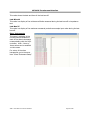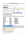
1
9120 System
With Touch Screen
Interface
USER’S MANUAL
Super Systems Inc.
7205 Edington Drive
Cincinnati, OH 45249
Ph : 513-772-0060, 800-666-4330
Fax: 513-772-9466
www.supersystems.com
SSi 9120 Touchscreen Interface
Table of Contents
Table of Contents ......................................................................................................................2
Section 1 – 9120 Touchscreen Interface .....................................................................................5
Safety: ......................................................................................................................................5
9120 Wiring Terminals ..............................................................................................................6
About the Model 9120: .............................................................................................................7
Electrical Installation: ...............................................................................................................7
Main Overview Screen ..............................................................................................................8
Menu Screens ......................................................................................................................... 10
System Information......................................................................................................................... 11
Alarm Log ....................................................................................................................................... 11
Event Log ........................................................................................................................................ 11
Shut down interface ........................................................................................................................ 12
Burnoff ........................................................................................................................................... 12
Slave Communications Status .......................................................................................................... 12
Auxiliary Analog Input ..................................................................................................................... 13
PID Loop Setup................................................................................................................................ 13
Burnoff Setup ................................................................................................................................. 16
Relay Assignments .......................................................................................................................... 16
Redundant Probe Setup .................................................................................................................. 17
Communications Setup ................................................................................................................... 18
Furnace Setup ................................................................................................................................. 20
Instrument Assignments.................................................................................................................. 22
Atmosphere Instruments ...................................................................................................................22
Temperature Instruments ..................................................................................................................22
Event Instruments..............................................................................................................................23
Analog Input Setup ......................................................................................................................... 23
Analog Output Setup ....................................................................................................................... 25
Alarm Setup .................................................................................................................................... 27
Aux Analog Input Setup ................................................................................................................... 29
Overview ...........................................................................................................................................30
Equipment needed.............................................................................................................................30
Calibration Procedure ........................................................................................................................30
4586 – 9120 With Touch Screen Interface
Page 2 of 80
SSi 9120 Touchscreen Interface
Input - Zero Calibration ......................................................................................................................30
Input – Span Calibration .....................................................................................................................31
Cold Junction .....................................................................................................................................31
Calibration ...................................................................................................................................... 31
Overview ...........................................................................................................................................31
Equipment needed.............................................................................................................................32
Calibration Procedure ........................................................................................................................32
Input - Zero Calibration ......................................................................................................................32
Input – Span Calibration .....................................................................................................................33
Output – Zero Calibration...................................................................................................................33
Output – Span Calibration ..................................................................................................................33
Cold Junction .....................................................................................................................................34
Tuning Assistant .............................................................................................................................. 34
Configuration .................................................................................................................................. 35
Alarm Text .........................................................................................................................................36
Edit Event Text ...................................................................................................................................36
Compact Database .............................................................................................................................36
Communications Setup ......................................................................................................................37
Read/Write Data ................................................................................................................................38
Edit Trend Charts ...............................................................................................................................38
Edit Datalogger ..................................................................................................................................39
Reset Datalogger................................................................................................................................40
Shut Down Interface ..........................................................................................................................40
Return................................................................................................................................................40
Chart Screen ........................................................................................................................... 41
Chart Menu..................................................................................................................................... 41
Section 2 – 9120 Configurator 2.0 Menus ................................................................................ 44
Burnoff ........................................................................................................................................... 44
Slave Instruments ........................................................................................................................... 45
Aux Analog Inputs ........................................................................................................................... 46
Burnoff Setup ................................................................................................................................. 46
PID Loop Setup................................................................................................................................ 47
Furnace Setup ................................................................................................................................. 49
Communications Setup ................................................................................................................... 51
Slave Instrument Setup ................................................................................................................... 53
Analog Input Setup ......................................................................................................................... 55
Analog Output Setup ....................................................................................................................... 57
Relay Assignments .......................................................................................................................... 58
Alarm Setup .................................................................................................................................... 59
4586 – 9120 With Touch Screen Interface
Page 3 of 80
SSi 9120 Touchscreen Interface
Calibration ...................................................................................................................................... 60
User Calibration .................................................................................................................................61
Full Calibration ...................................................................................................................................62
Alternate PID Setup......................................................................................................................... 63
RPS Configuration ........................................................................................................................... 64
Aux Input Module Offset Correction ................................................................................................ 64
Section 3 – 9120 Web Pages .................................................................................................... 66
Appendix A - PID Loop Factory Default Configurations ............................................................. 71
Appendix B – Changing the Date/Time on the Touchscreen ..................................................... 74
Appendix C - Typical Electrical Drawing ................................................................................... 75
Appendix D - Spare Parts......................................................................................................... 76
Appendix E – Installing SD Recorder ........................................................................................ 77
Appendix F – Flash Card Management .................................................................................... 79
Revision History ...................................................................................................................... 80
4586 – 9120 With Touch Screen Interface
Page 4 of 80
SSi 9120 Touchscreen Interface
Section 1 – 9120 Touchscreen Interface
Safety:
•
Safety Symbols - Various symbols are used on the instrument. They have the following
meaning:
!
Caution (refer to the accompanying documents)
•
Grounding of the temperature sensor shield - In some installations, it is common practice to
replace the temperature sensor while the controller is still powered up. Under these
conditions, as additional protection against electric shock, it is recommended that the shield of
the temperature sensor be grounded. Do not rely on grounding through the framework
of the machine.
•
Installation requirements for EMC - To ensure compliance with the European EMC directive,
certain installation precautions are necessary. When using relay or triac outputs, it may be
necessary to fit a filter suitable for suppressing the emissions. The filter requirements will
depend on the type of load. For typical applications, it is recommended to use Schaffner
FN321 or FN612.
•
Routing of wires - The wiring for the low voltage DC, and particularly the sensor, input should
be routed away from high-current power cables. This will minimize the pick-up of electrical
noise. When it is impractical to do this, use shielded cables with the shield grounded at one
end.
4586 – 9120 With Touch Screen Interface
Page 5 of 80
SSi 9120 Touchscreen Interface
9120 Wiring Terminals
4586 – 9120 With Touch Screen Interface
Page 6 of 80
SSi 9120 Touchscreen Interface
About the Model 9120:
The SSi 9120 is a single or dual loop blind controller/signal conditioning/data concentrating device
that can be used in carbon, oxygen, millivolt, SSi redundant probe, simple nitriding and universal
dual loop applications. The 9120 is supplied with Ethernet communications capability and has a
limited web server for thin client control and supports ModbusTCP host communications. Serial
I/O includes two (2) RS-232 ports and three (3) RS-485 ports. As a data concentrator, the 9120
is capable of communication to SSi's analog input modules as well as up to 25 slave serial
instruments and supports host communications via Modbus over RS232 or RS485 or ModbusTCP
communications.
The SSi 9120 Controller is a single or two loop device that can be configured to be used for
control of:
% Carbon
Dew Point
Oxygen
Millivolt
Redundant Probe
Simple Nitrider
Dual Loop
Temperature Mode
Electrical Installation:
The Model 9120 comes mounted on a DIN rail, pre-wired and tested. AC power needs to be
connected to the 24VDC power supply. See the section Typical Electrical Drawing for other
required connections.
4586 – 9120 With Touch Screen Interface
Page 7 of 80
SSi 9120 Touchscreen Interface
Main Overview Screen
Using the operator interface shown below you can configure the Model 9120.
The Main Overview screen will be the initial screen that is displayed when the Touchscreen is first
started up. The Main Overview screen will display each loop’s: type, setpoint, current value,
output mode, output, the activated/deactivated inputs and outputs, any messages, as well as the
Menu button and the Chart button. Any activated inputs or outputs will be lit up. In the picture
above, no inputs are activated, and outputs 0 and 7 are activated. Note on Inputs and Outputs –
The numbering on the display starts at 0 instead of 1, so input 2 shown above is actually input 3,
and output 4 is actually output 5. Any activated output will also be lit up on the Touchscreen
unit. The red bar will display any messages.
The list of runtime messages displayed depends on the setup of the 9120 instrument.
Nitrider:
• H2 cell communications failure – There is a problem with the communications with
the H2 cell
% C:
• Next burnoff in XX hours XX minutes – This will display the time left until the next
burnoff is performed. The screen will also display any burnoff messages, such as the
current remaining time of a burnoff, if a burnoff is being performed.
Redundant Probe:
• Probe n active – indicates which probe is selected. This message may be followed by:
o Selection n forced by digital input – Indicates that the selected probe has
been forced by digital input. Digital input 1 selects probe 1; input 2 selects probe
2.
o User controlled – Indicates that the probe has been manually selected by the
operator.
4586 – 9120 With Touch Screen Interface
Page 8 of 80
SSi 9120 Touchscreen Interface
Out of band condition detected – Indicates that the current probe has just
gone out of band
o Changing to probe n in sss seconds – Indicates that the specified probe will be
selected in the time frame provided. The message will count down while the timer
is active.
• Both inputs less than 950 mV – Neither probe can be selected when both inputs are
less than 950 mV.
• Input n over 1300 mV – The indicated input is over range.
• Both inputs over 1300 mV – Both inputs are over range.
• Probe Deviation – The selected alarm is active. See the alarms section for instructions
on setting up the alarms.
The list of error conditions is:
• Alarm 1, Alarm 2, or Alarm 3 – The selected alarm is active. See the alarms section for
instructions on setting up the alarms. Note: The alarm text will always be displayed if an
alarm is active regardless of the 9120’s setup.
The Menu button will display the menu options that will allow the user to configure the 9120
unit. The Chart button will display the chart screen. See the Menus Screens sections for
instructions on the menus and the Chart Screen.
o
4586 – 9120 With Touch Screen Interface
Page 9 of 80
SSi 9120 Touchscreen Interface
Menu Screens
The menu screen will allow the user to configure the 9120 unit, based on the login level. When
the menu list is first displayed, the
user will be automatically logged in at
the Operator-level. The number of
menus will vary based on the login
level. The default login for
Supervisor is a 1. The default login
for Administrator is 2. The Operator–
level will have the following menu
items:
• System Information
• Alarm Log
• Event Log
• Shut down interface
• Burnoff
• Slave Communications
Status
• Auxiliary Analog Input
The Supervisor-level will have the following menu items:
• Alarm Log
• Event Log
• Shut down interface
• Burnoff
• Slave Communications Status
• Auxiliary Analog Input
• PID Loop Setup
• Burnoff Setup
• Relay Assignments
• Redundant Probe Setup
The Administrator-level will have the following items:
• Alarm Log
• Event Log
• Shut down interface
• Burnoff
• Slave Communications Status
• Auxiliary Analog Input
• PID Loop Setup
• Burnoff Setup
• Relay Assignments
• Redundant Probe Setup
• Communications Setup
• Furnace Setup
• Instrument Assignments
• Analog Input Setup
• Analog Output Setup
4586 – 9120 With Touch Screen Interface
Page 10 of 80
SSi 9120 Touchscreen Interface
•
•
•
•
•
Alarm Setup
Aux Analog Input Setup
Calibration
Tuning Assistant
Configuration
There is also an SSi-special-level that can only be accessed with the passcode that can be
provided by Super Systems Inc at 800-666-4330. Currently, the menu list for this level is the
same as the list for the Administrator-level. To select a menu item, highlight the item by clicking
on it and pressing the Detail button. The Login button will allow the user to login as a different
access level. The Return button will allow the user to return to the main screen.
System Information
This screen will display some general system
information about the 9120 Touchscreen. This screen
will be useful for troubleshooting when communicating
with an SSi representative. This screen will display the
9120 instrument’s version number, the Touchscreen
software’s version number, SSi’s phone number, and a
link to the SSi website.
Alarm Log
This screen will display any
active alarms, as well as
any historical alarms. When
the “Active” check box is
checked, the screen will
display only the active
alarms. When the checkbox
is unchecked, the screen
will display historical alarms.
The historical alarms can be
displayed by day using the date control and the green arrow buttons.
Event Log
This screen will display any
active events, as well as any
historical events. When the
“Active” check box is checked,
the screen will display only the
active events. When the
checkbox is unchecked, the
screen will display historical
4586 – 9120 With Touch Screen Interface
Page 11 of 80
SSi 9120 Touchscreen Interface
events. The historical events can be displayed by day using the date control and the green arrow
buttons.
Shut down interface
This option will shut down the 9120 unit interface.
This option should be used before turning off the
power to the 9120 unit to verify that all the
information has been saved. The user will need to
verify the shutdown process. Once the interface
has been shut down, it can be restored simply by
cycling power to the unit, or by pressing the reboot
button on the screen, circled in red on the picture.
Burnoff
When a probe is in a furnace, soot will collect in the
end of the probe, which will have a negative effect on
the performance of the probe. Burnoffs are used to
clean out the built-up carbon by burning it off of the
probe. This screen will display: the current millivolts,
T/C temperature reading, the start millivolts and start
T/C temperature reading, the date of the last burnoff,
the last minimum millivolts reading, and the last
maximum T/C temperature reading. The last line will
display the status of the burnoff. The options can be:
Burnoff, Burnoff Recovery, or Idle. The burnoff
settings can be modified in the Burnoff Setup menu
option.
Slave Communications Status
This page is a display of the current process variables
of each of the slave instruments communicating with
the 9120 controller. Note – None of these values can
be modified on this screen. The slave instruments can
be set up in the Instrument Assignments menu option.
4586 – 9120 With Touch Screen Interface
Page 12 of 80
SSi 9120 Touchscreen Interface
A [N/A] displayed means that the slave instrument has not been set up yet. A Bad means that
communications are not functioning properly or that the instrument has been set up improperly.
Note: Twenty-five (25) slave instrument statuses will be displayed on this screen.
Auxiliary Analog Input
This menu option shows the process variables for the
auxiliary analog inputs of the 9120 controller. Note –
None of these values can be modified on this screen.
The auxiliary analog inputs can be set up in the Aux
Analog Input Setup menu option.
PID Loop Setup
PID is the tuning parameters entered for each Process Variable loop.
Prop Band (0 for On/Off)
This is the proportional band field. This
represents the P in PID. P = Proportional.
This is a field in which you want the process
variable to stay around the setpoint. Clicking
on the value will allow the user to change the
value. The range for the proportional band
value is 0 – 9999.0.
Reset
This is the reset field. This represents the I in
PID. I = Integral. This is the actual
temperature being monitored over a period of
time and then averaged to keep within the
Proportional band. The reset is in repeats per minute. This helps to eliminate offset. Clicking on
the value will allow the user to change the value. The reset range 0 – 10000.00.
Rate
This is the rate field. This represents the D in PID. D = Derivative. This is the sudden change or
rate in the temperature. This rate is in minutes. This affects the controller output which is
proportional to the rate of change of the measurement and will control the amount of output by
time restraints. Thus derivative takes action to inhibit more rapid changes of the measurement
than proportional action. Derivative is often used to avoid overshoot. Clicking on the value will
allow the user to change the value. The range for the rate is 0 – 10000.00. The rate is not
typically used for heating/carbon.
Mode
This is the mode of the loop. Clicking on the value will allow the user to change the value.
4586 – 9120 With Touch Screen Interface
Page 13 of 80
SSi 9120 Touchscreen Interface
The following is an explanation of the dual/single and direct/reverse properties:
Dual – This has two output relays which can increase and decrease to achieve your SP.
Single – This has one relay which works in only one direction to achieve your SP.
Direct - If the PV - SP is a positive number and the output would bring the PV down toward
setpoint, then that is direct.
Reverse – If the PV - SP is a negative number and the output would bring the PV up toward
setpoint, then that is reverse
Example: If a 12 mA output drives a 0 degree F temp. (PV) up to a 1200 degree F temp. (SP),
this would be REVERSE, and since this would take a SINGLE output from the controller, the Mode
for the Temperature Loop is Single Reverse.
The mode values can be:
Dual Reverse
Single Reverse
Dual Direct
Single Direct
Integral Preset
This field provides an offset for the starting point for PID control, also referred to as “Load Line”
or “Manual Reset”. Clicking on the value will allow the user to change the value. The range for
the integral preset is -100 to 100.
Cycle Time
Clicking on the value will allow the user to change the value. This field is typically set to the valve
travel time multiplied by 1.5. The cycle time range can be 0 – 500.
Setpoint Change Limit
This is a smart time feature that allows the Process Loop to use PB only without Reset until the
Process Variable drops below the percent output set under this category.
It is used to eliminate overshoot.
The Output percentage selected under this category must be above the normal operating output
percentage of the furnace at heat.
Clicking on the value will allow the user to change the value.
Example – if the furnace runs at 40% output at heat for the maximum load, the setpoint change
limit should be set to 60%.
The value can be:
OFF
80 %
70 %
60 %
50 %
40 %
30 %
20 %
Low Limit
This is the low limit field. Clicking on the value will allow the user to change the value. The range
is –100 to 100.
4586 – 9120 With Touch Screen Interface
Page 14 of 80
SSi 9120 Touchscreen Interface
High Limit
This is the high limit field. Clicking on the value will allow the user to change the value. The
range is –100 to 100.
0 Setpoint Stops Control
If the Setpoint is zero, then all outputs are turned off. Clicking on the value will allow the user to
change the value. The option is either Yes or No.
IN1 high stops control
If input 1’s high limit is reached, then all outputs are turned off. The value can either be Yes or
No.
IN2 high stops control
If input 2’s high limit is reached, then all outputs are turned off. The value can either be Yes or
No.
IN3 high stops control
If input 3’s high limit is reached, then all outputs are turned off. The value can either be Yes or
No.
PID Auto Switch
This is the PID auto switch field. The value can either be Yes or No.
Switch Point PID 1 -> 2
This is the PID Switch Point field. The range is –500 to 4000.
Switch Point PID 2 -> 3
This is the PID Switch Point field. The range is –500 to 4000.
Overshoot Limit Gain
This is the Overshoot limit gain field. When calculating the control action sometimes the
calculation would call for more than 100%, which is not possible. The output is limited to 100%,
or whatever was set in the High Limit field. The difference of the unlimited minus the limited is
multiplied by the overshoot limit gain and divided by 100. This is subtracted from the control
output. If the gain is 0 there is no effect. Under normal control, the unlimited equals the limited
and there is no effect. If there is a big change where the control loop drives hard, then the effect
is to limit the drive as it approaches setpoint and limit the overshoot.
The limited is the values set in the upper and lower limits fields. The unlimited would be what is
calculated before limiting. For a big setpoint change, the calculations may compute 150%
output, but the true output is limited to the upper limit. The range is 0 to 9999.
Setpoint Lower Limit
This is the setpoint lower limit for the loop. The range is -500 to 4000.
Setpoint Upper Limit
This is the setpoint upper limit for the loop. The range is -500 to 4000.
4586 – 9120 With Touch Screen Interface
Page 15 of 80
SSi 9120 Touchscreen Interface
Use Input 3 as remote SP
This will allow the user to use input 3 as a remote setpoint. The options are: yes or no.
Control Input
This will allow the user to view the input that will act as a control T/C. This setting is fixed and cannot be
changed by the user.
Burnoff Setup
This menu option allows the user to
modify the settings that are associated
with the probe burnoff (menu option
Burnoff).
Burnoff Time (sec)
The amount of time from the beginning of
the burnoff to the end of the burnoff
measured in seconds. The range is 0 to
600.
Burnoff Recovery Wait Time (sec)
The amount of time allotted to allow the
probe measurements to return to a stable,
accurate range after the burnoff is
complete. This is measured in seconds.
The control output is held until this time is
elapsed. The range is 0 to 300.
Burnoff Interval (min)
The amount of time between the beginning of one burnoff and the beginning of the next scheduled burnoff
measured in minutes. The range is 0 to 10080.
Burnoff Minimum Millivolts
The minimum measured millivolt tolerance of the probe required to start a burnoff. If the millivolts value is
exceeded the burnoff will stop. This is done to help maintain the life and the accuracy of your probe.
The range is 0 to 2000.
Burnoff Maximum Temperature
The maximum measured temperature allowed during a burnoff. If the temperature value is
exceeded the burnoff will stop. This is done to help maintain the life and the accuracy of your
probe. The range is 0 to 4000.
Relay Assignments
4586 – 9120 With Touch Screen Interface
Page 16 of 80
SSi 9120 Touchscreen Interface
This screen will display a description of
the eight relay assignments. The eight
“Outputs” on the front of the unit
represent the eight relay assignments,
where Output #1 = Relay Assignment 1,
etc. Most of the relay assignments are
fixed in the unit. Relay 1 is the loop 2
control relay. Relay 2 is the input 2 high
limit relay. Relay 3 is the loop 1
increase relay. Relay 4 is the loop 1
decrease relay. Relay 6 is the probe
burnoff relay. Relay 8 is the any alarm
relay. Relay 7 is the only relay that can
be assigned.
Redundant Probe Setup
This menu option will allow the user to configure the 9120 for RPS functionality.
Alarm band (mV)
This is the millivolt difference that must be observed for the RPS to change probes. For example,
when the RPS is selecting the highest
probe with probe 1 as 1055 mV and a
band of 20 mV, and if probe 2 hits 1076
mV, the RPS will start counting down the
Alarm Delay timer (below). When the
delay times out, probe 2 would be
selected. If probe 2 comes back in band
(drops to 1075), the timers starts over
again. The range is 0 to 600.
Alarm delay (min)
This is the number of minutes that the
RPS waits to switch probes when an outof-band condition is detected. Note -
There is a 950 mV low limit for an alarm.
This condition is typically found during a
burnoff, so the alarm will not be active
when the input drops below 950 mV.
The range is 0 to 9999.
Selected Probe
Indicates which probe is selected. Note – This field is only editable when the Probe select mode
(below) is set to no auto switch. The options are: 0 or 1. Note – The number of the probe is 0based, so “0” = probe 1 and “1” = probe 2.
4586 – 9120 With Touch Screen Interface
Page 17 of 80
SSi 9120 Touchscreen Interface
Probe select mode
This determines how the specified probe is selected. The options are: highest mV, lowest mV,
or no auto switch (manual mode).
Communications Setup
This menu option will allow the user to
configure the communications settings
for the 9120 unit. It is strongly
recommended that none of these
settings be modified without
assistance from Super Systems at
800-666-4330.
RS-232B Baud
This will allow the user to set the RS232B baud rate. This must be set to
19200 for the Touchscreen.
The options are:
1200
14400
57600
2400
19200
76800
4800
28800
115200
9600
38400
RS232B Mode
This will allow the user to set the RS232B mode. Note – This must be set to Modbus for the
Touchscreen. The options are: Modbus master or Modbus.
RS-232A Baud
This will allow the user to set the RS-232A baud rate. This must be set to 19200 for the
Touchscreen. Note – This option is fixed at 19200 and is not currently used in the 9120
Touchscreen.
The options are:
1200
14400
57600
2400
19200
76800
4800
28800
115200
9600
38400
RS232A Mode
This will allow the user to set the RS232A mode. This must be set to Modbus for the
Touchscreen. The options are: Modbus, Cal Term, and Televac. Note – This option is fixed
at 19200 and is not currently used in the 9120 Touchscreen.
Host 485 Baud
This will allow the user to set the Host 485 baud rate. This must be set to 19200 for the
Touchscreen.
The options are:
1200
14400
57600
2400
19200
76800
4586 – 9120 With Touch Screen Interface
Page 18 of 80
SSi 9120 Touchscreen Interface
4800
9600
28800
38400
115200
Host 485 Mode
This will allow the user to set the Host 485 mode. This setting is fixed to Modbus for the
Touchscreen.
Host 485 Address
This will allow the user to set the Host 485 address. The range is 0 to 249.
Slave 1 Baud
This will allow the user to set the Slave 1 baud rate.
The options are:
1200
14400
57600
2400
19200
76800
4800
28800
115200
9600
38400
Slave 1 Mode
This will allow the user to set the Slave 1 mode. The options are: MMI, Modbus master,
Yokogawa, or Modbus host.
Slave 2 Baud
This will allow the user to set the Slave 2 baud rate.
The options are:
1200
14400
57600
2400
19200
76800
4800
28800
115200
9600
38400
Slave 2 Mode
This will allow the user to set the Slave 2 mode. The options are: MMI, Modbus, ADAM, SSi
Analog Input Board, or Yokogawa.
IP Address
This option will allow the user to modify
the IP address of the 9120 Instrument
only. The address must be supplied in a
999.999.999.999 format, or it will not be
accepted. Contact Super Systems at 800666-4330 or your IT department before
changing any of the IP addresses. Note –
Communications may go down once the IP
address has been changed and before the
rest of the settings, i.e. the Configuration
menu Communication Setup menu,
have been updated.
4586 – 9120 With Touch Screen Interface
Page 19 of 80
SSi 9120 Touchscreen Interface
Subnet Mask
This option will allow the user to modify the IP subnet mask of the 9120 Instrument only. The
address must be supplied in a 999.999.999.999 format, or it will not be accepted. Contact Super
Systems at 800-666-4330 or your IT department before changing any of the IP addresses.
Gateway
This option will allow the user to modify the IP gateway of the 9120 Instrument only. The
address must be supplied in a 999.999.999.999 format, or it will not be accepted. Contact Super
Systems at 800-666-4330 or your IT department before changing any of the IP addresses.
Furnace Setup
This screen will allow the user to
configure the furnace settings. Do not
make any adjustments on this screen
without first contacting Super Systems
Inc at 800-666-4330.
Date and Time
This option will allow the user to
change the current date and time on
the 9120 controller, not the touch
screen. The date and time that is
recorded on the flash card (and,
therefore, the datalog data) is the
date and time of the Advantech
display, not the 9120 instrument.
To change the date and time of
the touch screen, see Appendix B
– Changing the Date/Time on the Touchscreen. Note – The initial date and time displayed
will be the system time of the Touchscreen, not the current time on the 9120 instrument.
PVT Type
The PVT type is the mode the device runs in (Carbon, Dewpoint, etc.). The mode selected
determines the calculations and scaling for the Process Variable.
The values for the PVT type are:
Carbon
Dew Point
Oxygen
Millivolt
Redundant Probe
Simple Nitrider
Dual Loop
Temperature
This value determines the specific temperature scale to be used. Clicking on the value will allow
the operator to change the value. It can be either Degrees °F or degrees °C.
Web Level 1 Code
4586 – 9120 With Touch Screen Interface
Page 20 of 80
SSi 9120 Touchscreen Interface
This value is the supervisor-level passcode for any web-based operations with the 9120
controller. Clicking on the value will allow the operator to change the value. The range for the
passcode is -32767 to 32767.
Web Level 2 Code
This value is the administrator-level passcode for any web-based operations with the 9120
controller. Clicking on the value will allow the operator to change the value. The range for the
passcode is -32767 to 32767.
Web Change Enable
This will either enable or disable the web change feature, which will allow changes to be made
over the web page for the 9120 controller. Clicking on the value will allow the operator to change
the value. Select either a 0 (Web Change Disable) or a 1 (Web Change Enable).
O2 Mode
This value will allow the operator to select the oxygen mode.
Clicking on the value will allow the operator to change the value.
The options are:
% with control
Monitor
Offset log with control
Sample Pump Mode
This menu option will allow the user to turn the sample pump On or Off. For the HP PVT types
(% Carbon, Dewpoint, Oxygen, Millivolt, and Redundant Probe), there is the option to set
a minimum temperature in order for the pump to run. See the “Minimum Temp/Pump Run”
description below.
Minimum temp/pump run
This option will set the minimum temperature for the pump to run, if that feature is used. A 0
value will disable the minimum temperature feature. Note - The furnace that is being sampled
must have its temperature connected to input 3 for the pump minimum temperature feature to
work. The range is 0 to 32767.
Remote Setpoint
This option will allow the user to select where the remote setpoint will come from. The options
are:
None
Slave 1 PV
Slave 2 PV
Slave 1 SP
Slave 2 SP
Input 3
Remote Setpoint Hysteresis
This option will allow the user to enter the remote setpoint hysteresis. The range is 0 to 32767.
Loop 2 PV source
4586 – 9120 With Touch Screen Interface
Page 21 of 80
SSi 9120 Touchscreen Interface
This option will allow the user to select the loop 2 PV source. The options are: Input 3 or Input
2.
Instrument Assignments
This menu option will allow the user to
set up the slave instruments for the
9120.
** All devices on the same slave port
must utilize the same protocol
** An address of zero (0) will disable
the instrument**
Some controllers (AC20, for example)
can provide dual functions (atmosphere
and events) and must have the same
address assigned for both.
Instruments
The 9120 unit breaks down the
instruments into three different types:
atmosphere, temperature, and event.
The atmosphere instruments are listed with a blue background. The temperature instruments are
listed with a pink background. The event instruments are listed with a yellow background. The
following is the list of instruments available as slave instruments:
Atmosphere Instruments
SSi AC20
Yokogawa 750
Honeywell UDC3300
Dualpro LP1 Modbus
Dualpro LP2 Modbus
Dualpro LP1 MMI
Dualpro LP2 MMI
Eurotherm 2402
Eurotherm 2500
Cabpro v3.5
Cabpro v3.0
CarbPC
9200 LP1
IR Base
MGA
Temperature Instruments
SSi 7EK
9200 LP1
SSi Quad AO1
Yokogawa 750
9200 LP2
SSi Quad AO2
Honeywell UDC3300
9200 LP3
SSi Quad AO3
Dualpro LP1 Modbus
9100 LP2
SSi Quad AO4
Dualpro LP2 Modbus
Eurotherm 2704 LP1
Yokogawa UT350
Dualpro LP1 MMI
Eurotherm 2704 LP2
Yokogawa 750 Lp 2
4586 – 9120 With Touch Screen Interface
Page 22 of 80
SSi 9120 Touchscreen Interface
Dualpro LP2 MMI
Eurotherm 2402
Eurotherm 2500
Unipro v3.5
Unipro v3.0
Carbpro v3.5 Slave
Carbpro v3.0 Slave
10Pro
Dualpro IN C
Eurotherm 2704 LP3
VC Base 1
VC Base 2
VC Base 3
VC Base 4
AIPC
SSi 7SL
AEC Flow Board
UMC800 LP1
Yokogawa UP350
Honeywell DCP551
Ascon 08
Event Instruments
SSi AC E
Yokogawa 750E
Mod Mux
Dualpro E Modbus
Dualpro E MMI
Carbpro E v3.5
Carbpro E v3.0
Eurotherm 2500
SSi 8-8
SSi 9200 E
Micrologix PLC
MCM Module
PLC5 DF1
SLC DF1
Address
This value allows the user to select the address that corresponds with the controller selected, with a range
of 0 to 255.
Port
This is the port that the slave instrument will use. The options are: Slave 1 or Slave 2.
Slave 1 – terminals 5(-), 6(+)
Slave 2 – terminals 22(+), 23(-).
Analog Input Setup
The 9120 controller has two analog
inputs. Each of the inputs comes with
a factory default configuration
dependent on the application (refer to
PVT type under the Furnace Setup
section). It can be modified prior to
shipment to your facility or in the field
by a technician or qualified/trained
person with the proper security code.
Analog Input Terminals:
Analog Input 1 – terminals 31 and 32
Analog Input 2 – terminals 29 and 30
4586 – 9120 With Touch Screen Interface
Page 23 of 80
SSi 9120 Touchscreen Interface
Input Type
The thermocouple type for most applications can be modified depending on your specific needs.
Please note that in some applications, some of the inputs DO NOT allow the user to modify the
Input type. Note - Before changing the input type, make sure to set the appropriate jumpers, if
necessary. The jumper will need to be manually changed on the input board before changing the
input type to a 10:1 setting (non-thermocouple types). To change the Input type, first select
which input you want to change by selecting it in the pull-down menu at the top of the screen.
Once selected, click OK and the displayed Input type under Value will be the current type.
The following is a list of the options:
T/C B
T/C S
T/C C
T/C T
T/C E
2.56 volts
T/C J
1.28 volts
T/C K
78.125 mV
T/C N
19.53125 mV
T/C NNM
4-20 mA ***
T/C R
25 volts ***
12.5 volts ***
781.25mv
195.3125 mV
*** When the specified input type is selected, a jumper located inside the case will
need to be placed on that specific input for reading this selection. If jumper is not
placed on input, then damage could occur to the board. ***
Filter time
The filter time is a factory applied averaging tool used to help maintain steady control in high EMI
environments. The filter time should not be adjusted with consulting SSI. The range is 0 to
32767.
Initial Scale
This is the initial scale value. Clicking on this value will display an input box from which the user
can select a new value. This could also be referred to as the starting value. For example, the
initial value is the value when 0 volts is on the selected input; or on a 4-20 mA input, it would be
the value at the selected input of 4 mA. The range is –32768 to 32767.
Full scale
This is the full scale value. Clicking on this value will display an input box from which the user
can select a new value. The range is –32768 to 32767.
Decimal Point Location
This is the decimal point location value. Clicking on this value will display an input box from
which the user can select a new value. This will affect the PV value and the location of the
decimal when it is displayed. The range is 0 to 4.
Open TC behavior
This is the open TC value. The options are: up scale, down scale, one trip point, or two trip
points.
Input Offset
4586 – 9120 With Touch Screen Interface
Page 24 of 80
SSi 9120 Touchscreen Interface
The input offset value is algebraically added to the input value to adjust the input curve on readout. Note - The input offsets are unscaled. The range is –32767 to 32767.
Trip Point 1 Setpoint
This is the trip point 1 setpoint value. The range is –32767 to 32767.
Trip Point 1 Force Value
This is the trip point 1 force value. The range is –32767 to 32767.
Trip Point 1 Direction
This is the trip point 1 direction. The options are: input above setpoint or input below
setpoint.
Trip Point 2 Setpoint
This is the trip point 2 setpoint value. The range is –32767 to 32767.
Trip Point 2 Force Value
This is the trip point 2 force value. The range is –32767 to 32767.
Trip Point 2 Direction
This is the trip point 2 direction. The options are: input above setpoint or input below
setpoint.
High Input Limit Setpoint
This is the setpoint for the high input limit. The range for this can be –32767 to 32767.
High Input Limit Hysteresis
This is the hysteresis for the high input limit. The range for this can be –32767 to 32767.
Analog Output Setup
The 9120 controller has the option of two analog outputs. The outputs are ranged for a 4 – 20
milliamp signal or a 0 – 20 milliamp signal. Each output comes with a factory default
configuration dependent on the application. Each output can be modified prior to shipment to
your facility or in the field by a supervisor.
Analog Output Terminals:
Analog output 1 – terminals 24 and 25
Analog output 2 – terminals 25 and 26
Assignment
The analog output assignment can be
modified depending on your system
requirements. To change the Assignment,
first select which analog output you want
to change by selecting it in the pull-down
menu. Select the desired assignment
from the list and click OK. The following
is a list of the options:
4586 – 9120 With Touch Screen Interface
Page 25 of 80
SSi 9120 Touchscreen Interface
PV 1 retrans
Loop 1 inc
Loop 1 dec
Loop 1 combo
PV 2 retrans
Loop 2 inc
Loop 2 dec
Loop 2 combo
PV3 retrans
Loop 3 inc
Loop 3 dec
Loop 3 combo
Input 1 retrans
Input 2 retrans
Input 3 retrans
Not Used
O2 offset log
SP1 retrans
SP2 retrans
SP3 retrans
Programmer ID number
Combo example for carbon – 4 – 12 mA Air
12 – 20 mA Gas
Offset
This is the starting point; the Process Variable value at which you get 4 milliamps. Clicking on
this value will display an input box from which the user can select a new value. The range is –
32767 to 32767.
Range
This is a Process Variable value between 4 and 20 milliamps. Clicking on this value will display an
input box from which the user can select a new value. The range is –32767 to 32767. Note -
The range, although not displayed with a decimal point, contains a decimal point that is
dependent on the process variable selected. For example, If the offset is 20 mV for 4 mA, and
you want 100 mV to be 20 mA, then your range should be 80. If the process variable is
temperature, then the range will be 80, since temperature PVs do not have a decimal. If the PV
is % Carbon, then the range will need to include the two decimal points for % Carbon. So, a
range of 80 will be entered as 8000. See below for more examples.
Current Selection
Provides the option of 4-20 mA or 0-20 mA control.
Offset and Range when assigned to a control loop
Inc -- 0 = 4mA, 100 = 20mA
Dec -- 0 = 4mA, -100 = 20mA
Example: if 4 – 20 mA = 800 mV - 1200 mV and PV is Temperature
Offset = 800 (starting point)
Range = 400
Example: if 4 – 20 mA = 800 mV - 1200 mV and PV is O2
Offset = 800 (starting point)
Range = 4000 (400.0)
Example: if 4 – 20 mA = 800 mV - 1200 mV and PV is % Carbon
4586 – 9120 With Touch Screen Interface
Page 26 of 80
SSi 9120 Touchscreen Interface
Offset = 800 (starting point)
Range = 40000 (400.00)
O2 Exponent Range
This menu option will allow the user to set the Oxygen exponent range. The range is -32767 to
32768.
Alarm Setup
The 9120 controller can be configured
to use three different alarms. Each of
the alarms consists of an alarm
setpoint, alarm source, alarm type,
hysteresis, smart alarm, alarm on
delay time, and a zero SP blocks alarm
value. The alarms come from the
factory with a default configuration
dependent on the application but also
can be modified prior to shipment to
your facility or in the field by a
supervisor.
Setpoint
This value is the setpoint for the
alarm. The range is from –32767 to
32767.
Alarm Source
This value is the source of alarms used.
The options are:
PV 1 Value
PV 2 Value
PV 3 Value
Input 1 Value
Input 2 Value
Input 3 Value
Percent output 1 Value
Percent output 2 Value
Percent output 3 Value
Alarm Type
This value is the type of alarms used.
The options are:
Process High
Process Low
Band, Normally Open
Band, Normally Closed
Deviation, Normally Open
Deviation, Normally Closed
4586 – 9120 With Touch Screen Interface
Page 27 of 80
SSi 9120 Touchscreen Interface
Deviation alarm is single sided. i.e. a +10 deviation will alarm when the PV is greater than SP +
10 but not neg. A -10 deviation will alarm when the PV is less than SP -10 but not on the positive
side.
The actual relay setup with that alarm will only energize depending on the setpoint. For the
standard alarms (1, 2, and 3), the user can select if the alarm condition is for above or below.
This will dictate when the relay will energize.
Example: alarm 1 set to plus 10F will alarm 11 degrees above setpoint and pull in the relay. It will
show alarm 10 degrees below but not pull in the relay.
A Band alarm will activate and energize the relay on both sides (+) and (-).
Note - some alarm types may be fixed at the current value.
Hysteresis
The hysteresis is in degrees, i.e. 10 hysteresis = 10 degrees.
Alarm hysteresis should not have a decimal place. It is in units. If it is a control loop doing on/off
control then the decimal place on the reset (hysteresis) should be ignored. The Hysteresis is a set
number that works with the alarm to help control a motor or pump longer to reach a set amount
to come back into band before it will shut off motor or pump.
Example: Using quench oil as an example, assume the SP is 200F. The alarm is set as a deviation
of +10F. At 210 the alarm is active and the pump will run to cool the oil. With a hysteresis of 8
degrees the alarm and pump will turn off at 202F. It will turn back on when it is 10 degrees
above setpoint. If the setpoint is still 200 then at 210 it is on again. Clicking on this value will
display an input box from which the user can select a new value.
The range is from -32767 to 32767.
Smart Alarm
This value is a display of the Smart Alarm status. A smart alarm is an alarm that works with a
Process Variable and when enabled it will not be active until the process variable is within band of
the setpoint.
Example: If the SP is 1700 and the band is 10 degrees the alarm will not be active until the PV
reaches 1690.
The value can be either Yes or No.
Alarm on delay time
This value is the on Delay Time for the Smart Alarm, in seconds. If the timer is utilized the alarm
will not be active until in band and the timer has timed out (this is in seconds).
Example: If you select 30, the output will not energize until 30 seconds after the alarm is active.
Clicking on this value will display an input box from which the user can select a new value.
Note – This value is fixed at No for Alarm 1.
4586 – 9120 With Touch Screen Interface
Page 28 of 80
SSi 9120 Touchscreen Interface
The range is from -32767 to 32767 seconds.
Zero SP Blocks Alarm
This value will allow a 0 setpoint to block an alarm. Note – This value is fixed at No for Alarm 1.
The options are either No or Yes. Note – Setting this value to Yes will force the Smart Alarm
value to be set to No.
Aux Analog Input Setup
This option will allow the user to select the input type for the auxiliary analog input boards, as
well as calibrate the boards.
Input 1 – Input 5
This will set the input type for the selected input.
The options are:
T/C B
2.5 Volts
T/C C
1.25 Volts
T/C E
160 mV
T/C J
80 mV
T/C K
40 mV
T/C N
20 mV
T/C NNM
4-20 mA/124Ω
T/C R
4-20 mA/62Ω
T/C S
T/C T
Calibration
This menu option will allow the user to calibrate the auxiliary analog inputs.
4586 – 9120 With Touch Screen Interface
Page 29 of 80
SSi 9120 Touchscreen Interface
Overview
The auxiliary analog inputs can be calibrated using the touch screen and a calibrator. Before
performing this procedure on a newly installed controller, the unit needs to be powered on for at
least thirty (30) minutes for a warm up period to allow the inputs/outputs to stabilize with the
environment.
Each auxiliary analog input has a zero and span calibration value. A cold junction trim value must
be calibrated for thermocouple inputs. The cold junction trim value must be performed, if
necessary, after the zero and span calibration.
Equipment needed
A certified calibrator(s) with the ability to source and measure millivolts, milliamps and
thermocouples is required. The appropriate connection leads are also required. A 24VDC 75-watt
power supply is required. It is important to note that when performing a zero or span calibration,
do not use regular thermocouple wiring. Instead, use any kind of regular sensor wire, or even
regular copper wire. To perform the calibrations, the user will need a calibrator that is capable of
sourcing volts, millivolts, and temperature.
Calibration Procedure
The calibration procedure for an auxiliary
analog input will be the same regardless of
which operation is being performed.
1. Zero Input: Source a zero mV value to
the terminals. Press the Calibrate
button.
2. Span Input: Source a specific mV value
to the terminals and enter the value in
the box. Press the Calibrate button.
3. Cold Junction Trim: Enter the
temperature of the input.
The user will need to select which calibration
type – Zero/Span or Cold Junction – is to be
performed and press the appropriate button
from the main calibration screen. The cold
junction trim value must be performed, if
necessary, after the zero and span
calibration.
Input - Zero Calibration
To perform a zero calibration on an input, verify
that the “Zero” option at the left is selected.
Select the target millivolts that will be sourced. Note – For a zero calibration, it is recommended
that 0 mV be sourced. The recommended millivolt source value will be displayed as well. The
mV value will be displayed on the screen under the appropriate input. Select the input(s) to be
calibrated. Press the Calibrate button to begin the calibration. The calibration status will be
displayed on screen. When it is over, the screen will display “Waiting to start zero/span
4586 – 9120 With Touch Screen Interface
Page 30 of 80
SSi 9120 Touchscreen Interface
calibration” once again. Once the zero calibration has finished, the span calibration can be
performed.
Input – Span Calibration
To perform a span calibration on an input,
verify that the “Span” option at the left is
selected. Select the target millivolts that
will be sourced. Note – For a span
calibration, it is recommended that 90 % of
the full range be sourced. The
recommended millivolt source value will be
displayed as well. The mV value will be
displayed on the screen under the
appropriate input. Select the input(s) to be
calibrated. Press the Calibrate button to
begin the calibration. The calibration status
will be displayed on screen. When it is
over, the screen will display “Waiting to
start zero/span calibration” once again.
Once the zero and span calibration have
finished, a cold junction trim can be performed, if necessary.
Cold Junction
The cold junction should be performed after any zero/span calibration. To perform a
cold junction, the corresponding T/C wire will need to be setup on the inputs. A specific
temperature will need to be sourced to the selected input. The input’s PV value will be displayed
on the screen. Determine the difference between the displayed PV value and the value that is
being sourced.
For example, assume that input 3 is setup for T/C type K, and 1000 ◦F is being sourced in. The
PV for input 3 is 1002 ◦F. The value displayed on the cold junction screen is the current
temperature of the terminals. Assume this value is 95.5 ◦F. In the number box, the user would
enter a -2 degree difference, or 93.5 ◦F, since the temperature sourced (1000 ◦F) – PV value
(1002 ◦F) = -2 ◦F. Press the Calibrate button to finish off the cold junction calibration. Return to
the main screen to see if the selected input’s PV value is now displaying the correct value of what
is being sourced. If necessary, repeat these steps to further calibrate the cold junction value.
Calibration
Overview
The series 9120 controller can be calibrated using the touch screen and a calibrator. Before
performing this procedure on a newly installed controller, the unit needs to be powered on for at
least thirty (30) minutes for a warm up period to allow the inputs/outputs to stabilize with the
environment.
4586 – 9120 With Touch Screen Interface
Page 31 of 80
SSi 9120 Touchscreen Interface
The series 9120 has three analog inputs.
Each range has a zero and span calibration
value. A cold junction trim value must be
calibrated for thermocouple inputs. The
cold junction trim value must be
performed, if necessary, after the zero
and span calibration. There are two
analog outputs each with a zero and span
value.
Equipment needed
A certified calibrator(s) with the ability to
source and measure millivolts, milliamps and
thermocouples is required. The appropriate
connection leads are also required. A 24VDC 75-watt power supply is required. It is important to
note that when performing a zero or span calibration, do not use regular thermocouple wiring.
Instead, use any kind of regular sensor wire, or even regular copper wire. To perform the
calibrations, the user will need a calibrator that is capable of sourcing volts, millivolts, and
temperature.
Calibration Procedure
The calibration procedure for an input or output will be the same regardless of which operation is
being performed.
1. Zero Input: Source a zero mV value to the terminals. Press the Calibrate button.
2. Span Input: Source a specific mV value to the terminals and enter the value in the box.
Press the Calibrate button.
3. Zero Output: Press the Ready button, which will set the output to 0%, or 4 mA. Measure
the current at the terminals and input the measured value. In the number box, use the
arrows or tap the box to enter the value with the key pad. Press the Calibrate button.
4. Span Output: Press the Ready button, which will set the output to 100%, or 20 mA.
Measure the current at the terminals and input the measured value. In the box, use the
arrows or tap the box to enter the value with the key pad. Press the Calibrate button.
5. Cold Junction Trim: Enter the temperature of the input.
Input - Zero Calibration
To perform a zero calibration on an input, verify
that the “Zero” option at the top is selected.
Select the target millivolts that will be sourced.
Note – For a zero calibration, it is recommended
that 0 mV be sourced. The recommended millivolt
source value will be displayed as well. The mV
value will be displayed on the screen. Press the
Calibrate button to begin the calibration. The
calibration status will be displayed on screen.
When it is over, the screen will display “idle” once
again. Once the zero calibration has finished, the
span calibration can be performed.
4586 – 9120 With Touch Screen Interface
Page 32 of 80
SSi 9120 Touchscreen Interface
Input – Span Calibration
To perform a span calibration on an input, verify
that the “Span” option at the top is selected.
Select the target millivolts that will be sourced.
Note – For a span calibration, it is recommended
that 90 % of the full range be sourced. The
recommended millivolt source value will be
displayed as well. The mV value will be displayed
on the screen. Press the Calibrate button to
begin the calibration. The calibration status will
be displayed on screen. When it is over, the
screen will display “idle” once again.
Output – Zero Calibration
To perform a zero calibration on an output,
verify that the “Zero” option at the top is
selected. Press the Ready button to begin
the process. Enter the mA value that is being
measured at the appropriate terminals (see
the 9120 Wiring Terminals section; the
appropriate terminals to measure will also be
displayed on the screen). Press the Calibrate
button to finish the calibration. The calibration
status will be displayed on screen. When it is
over, the screen will display “idle” once again.
Once the zero calibration has finished, the
span calibration can be performed.
Output – Span Calibration
To perform a zero calibration on an output,
verify that the “Span” option at the top is
selected. Press the Ready button to begin
the process. Enter the mA value that is being
measured at the appropriate terminals (see
the 9120 Wiring Terminals section; the
appropriate terminals to measure will also be
displayed on the screen). Press the
Calibrate button to finish the calibration.
The calibration status will be displayed on
4586 – 9120 With Touch Screen Interface
Page 33 of 80
SSi 9120 Touchscreen Interface
screen. When it is over, the screen will display “idle” once again.
Cold Junction
The cold junction should be performed
after any zero/span calibration. To
perform a cold junction, the corresponding
T/C wire will need to be setup on the inputs.
A specific temperature will need to be sourced
to the selected input. Return to the main
screen by pressing the Return button three
times to read the input’s PV value. Mark
down the displayed PV value and determine
the difference between the displayed PV value
and the value that is being sourced.
For example, assume that input 3 is setup for
T/C type K, and 1000 ◦F is being sourced in.
On the main display, the PV for input 3 is 1002 ◦F. Return to the Cold Junction menu under the
Calibration menu. The value displayed on the Cold Junction Calibration screen is the current
temperature of the terminals. Assume this value is 95.5 ◦F. In the number box, the user would
enter a -2 degree difference, or 93.5 ◦F, since the temperature sourced (1000 ◦F) – PV value
(1002 ◦F) = -2 ◦F. Press the Calibrate button to finish off the cold junction calibration. Return to
the main screen to see if the selected input’s PV value is now displaying the correct value of what
is being sourced. If necessary, repeat these steps to further calibrate the cold junction value.
Tuning Assistant
The tuning assistant menu option will
allow the user to automatically
generate the PID loop settings for the
control loops in the 9120 controller.
The tuning assistant can be performed
on either Loop 1 or Loop 2.
Note - The four buttons at the bottom
of the screen: Use UD, Use CD, Use
OD, and Use PI will be inaccessible
until some PID settings are loaded into
the PID settings list above the buttons.
The user can select the tuning option
from the top left of the screen. The
choices are: Relay and Limited
Relay. This option will allow the user
to limit the output value while the
controller is controlling the furnace. Normal operation will typically use 100 % output. When the
limited relay option is selected, the “Tuning Delta:” label and an edit box will be displayed. When
the Relay option is selected, the “Tuning Delta:” label and the edit box will be hidden. The
“Tuning Delta” value will be the amount to limit the controller by. Pressing the edit box will
display the numeric keypad, which will allow the user to enter the limiting value.
4586 – 9120 With Touch Screen Interface
Page 34 of 80
SSi 9120 Touchscreen Interface
The “Conservative” option will allow the user to minimize, if not remove, the possibility for an
overshoot of the setpoint. If a small overshoot is acceptable, leave the “Conservative” checkbox
unchecked. If, however, no overshoot is desired, then checking the “Conservative” checkbox will
accomplish this.
The process variable as well as the setpoint for the selected loop will be displayed below the
“Conservative” option.
Pressing the Start button will begin the
auto tune process. Note - The process
may take a few seconds to start. The
“Idle” line will change to display the
calibration process for the auto tune.
Note: The Start button will become the
Abort button while the calibration is
running. Pressing the Abort button will
abort the process. If the Abort button
is pressed while a calibration is running,
a message box will be displayed
confirming the action.
Pressing the Yes button will stop the
auto tune calibration and exit the
screen. The No button will cancel the
abort.
When the calibration is finished, the PID settings list will be populated with suggested values and
the four buttons underneath will be enabled. The line below the PID settings list will read “Idle”
again as well.
The user has the option to select only one of these sets of values: the Under Damped set (Use
UD), the Critically Damped set (Use CD), the Over Damped set (Use OD), or the PI set (Use PI).
To select the set of values, press the corresponding button. For example, to select the Critically
Damped set of values, press the Use CD button. The under damped values will reach the
setpoint faster, but there will be more overshoot involved. The over damped values will work to
minimize the overshoot, but it will be slower than the under damped values. The critically
damped values are considered the “optimum” values because they are a balance between the
under damped and over damped values with regards to time and overshoot. The PI values are
just the proportional band and the reset value (the P and the I from PID). This could be
applicable in an atmosphere loop, where the rate won’t have much effect.
Once a set of values has been accepted, the user can press the Return button to exit the screen.
The accepted values can be viewed on the PID Loop Setup menu option. Note - Once the screen
is closed out, the PID settings values will be lost. To populate these values again, another auto
tune routine will need to be run.
Configuration
This option will allow the user to set some general configuration settings.
The list of configurable items is:
• Alarm Text
• Edit Event Text
• Compact Database
• Communications Setup
• Read/Write Data
4586 – 9120 With Touch Screen Interface
Page 35 of 80
SSi 9120 Touchscreen Interface
•
•
•
•
Edit Trend Charts
Edit Datalogger
Reset Datalogger
Shut Down Interface
Alarm Text
This menu option will allow the user to
configure the text for the three main alarms on
the 9120. Highlight the alarm to be changed
and click on the Edit button. This action will
display the on-screen keyboard, which will
allow the user to modify the alarm text. To
save the changes to the alarm text, click on
the OK button. Clicking on the Cancel button
will not save any of the changes made.
Edit Event Text
This menu option will allow the user to configure
the text for the input and output events for the
9120. Select whether to edit the Input events or
the Output Events. Note – The list of events can
take a few seconds to load. The screen will
refresh after the list has been loaded. There are a
total of 148 input events, and 296 output events.
Highlight the event to be changed and click on the
Edit button. This action will display the on-screen
keyboard, which will allow the user to modify the
event text. To have that event data logged, check
the checkbox next to the event number. To save the changes to the event text, click on the
Save button. Clicking on the Return button will not save any of the changes made. Note –
Clicking on the Save button will not close the Edit Event Text screen.
Compact Database
This menu option will automatically compact the TS9120.sdf database. This database will keep
track of all of the alarms, events, recipes, and system events that occur on the 9120. When
records are added, space is reserved in the database table for the maximum amount of
characters, regardless of the actual number of characters in the record. Once the record is
added, this space is not released. Instead, it will still be associated with the record, thereby
adding to the total disk space and slowing down the communication time with the database.
4586 – 9120 With Touch Screen Interface
Page 36 of 80
SSi 9120 Touchscreen Interface
Compacting the database will free up this extra space, which will speed up the amount of time it
takes the software to communicate with the database.
Communications Setup
This menu option will allow the user to determine
how the Touchscreen will communicate with the
9120 instrument.
The Media option will be the type of connection the
Touchscreen is using to connect to the 9120. The
options are:
• COM1
• COM2
• COM3
• COM4
• Ethernet
If COM1 through COM4 is selected, the user will
have to set the Address and the Baud rate as well. If Ethernet is selected, then user will have to
enter the IP address of the 9120 instrument
The Address option is the slave address of the 9120 instrument for the COM port
communications, or the Ethernet IP address for Ethernet communications. For the COM port
communications, the address will range from 1 to 250. For Ethernet communications, the
address must be supplied in a 999.999.999.999 format, or it will not be accepted.
The Baud option is the baud rate for the COM port communications. The options are:
• 1200
• 2400
• 4800
• 9600
• 14400
• 19200
• 28800
• 38400
• 57600
• 76800
• 115200
4586 – 9120 With Touch Screen Interface
Page 37 of 80
SSi 9120 Touchscreen Interface
Read/Write Data
This menu option is protected by the SSi special
passcode. Contact SSi at 800-666-4330 to obtain
this passcode, and before making any changes.
This menu option is used mainly for technical
support reasons. It will read the registers from the
9120 and display those registers on the screen. The
user will be able to read from and write to the
9120’s registers. When the screen is first displayed,
it will read the first 100 registers from the 9120 and
display them in a column format. The top of the list
will show “0”, “10”, “20”, etc. These are the column
headers. Each value in the column will be a logical
increment of the header, where the first value in the
column equals the header value. For instance, column “0” will start with register 0, which in the
picture has a value of “113”. The next value down is register 1, which has a value of “5”. The
next value down is register 2, which has a value of “1”, etc. So, column “40”, 4 values down is
register is register 43, which has a value of “2000”.
The number box in the top left of the screen is the beginning register to read from. This will
default to 0 when the screen starts. To read registers 100 – 199, edit the value to read “100”.
Note – changing the value will automatically begin the read process. This process could take a
few seconds to complete.
The “Write offset” value will allow the user to write a specific value listed in the “Write value” box
to the register listed in the “Write offset” box. Click on the Write button to write the value to the
register. Click on the Return button to return to the Configuration menu.
Edit Trend Charts
This menu option will allow the user to add, modify, or
delete a trend chart from the Touchscreen. A trend
chart is what displays the data logged data on the
Touchscreen chart. Each trend chart file is made up of
at least one trend, which represents one data value to
display, such as temperature setpoint, or actual
temperature value. The menu starts off with a blank
new trend chart
file. The buttons
at the top will
affect the trend
chart file itself.
Open will allow the user to open a selected trend chart.
Delete will allow the user to delete a selected trend chart.
Save will save the opened trend chart’s changes. Save As
will allow the user to save the opened trend chart under a
new file name. Once a chart has been opened, the buttons
under the list of trends can be used. Add will add a new
trend to the chart file. Edit will allow the user to edit a
selected trend. Delete will allow the user to delete a
selected trend.
4586 – 9120 With Touch Screen Interface
Page 38 of 80
SSi 9120 Touchscreen Interface
Each trend will have the same number of fields to be filled out when adding or editing. The
“Name” is merely the name of the trend. This is how the trend will be identified on the chart
screen. It will also be the physical name of the trend chart file. The list of values in the “Data”
list are the specific registers that are being data logged. This list can be modified in the Edit
Datalogger section that follows this section. Select the register that corresponds to the desired
point to view. The “Min” field is the minimum display value for the chart. The “Max” field is the
maximum display value for the chart. The “Expression” field will format how the data value will
be displayed on the screen. To display the data value as it is, enter an “x” as the expression.
Note – Data values are stored in the 9120 without any decimal places, so formatting will be
necessary for some values. If the data value was monitoring % Carbon, then the expression
would be “x * 0.01”, since % Carbon values will need decimal places shown on the display. The
“Format” field will control how the data value is displayed. This field works with the “Expression”
field for display purposes. To display the data value as it is, enter a “0”. Note – Data values are
stored in the 9120 without any decimal places, so formatting will be necessary for some values.
If the data value was monitoring % Carbon, then the format would be “0.00”, since % Carbon
values will need decimal places shown on the display.
The following example will illustrate the difference between “Expression” and “Format”. Assume
that the data value represents a % Carbon value, and it’s value is 3.47. This will be saved in the
9120 register as 347. Assume that “Expression” is set up as “x * 0.01” and “Format” is set up as
“0.0”. Whenever the data value is logged, it will be logged as 3.47, but it will display 3.8, since
the “Format” only allows for 1 decimal place. If “Format” was “0.00”, then the data value will
display 3.47. However, if “Expression” was “x * 0.1” and “Format” was “0.0”, the data value
would be logged as 34.7 and display 34.7. If the “Format” was “0.00”, the data value would be
displayed as 34.70.
The color next to the “Format” field will allow the user to select which color the trend line will
show up as on the chart.
The “Units” field will be the description of what kind of data value is being logged. This can be
any value, such as “°F”, or “%C”, or “mV”.
The “Line Width” field will allow the user to set the thickness of the trend line on the chart.
Lower numbers equal thinner lines, and higher numbers equal thicker lines. This may come in
handy if both actual temperature and temperature setpoint have the same color. Actual
temperature can have a line width of “1”, and temperature setpoint can have a line width of “2”.
This will allow similar trends to be grouped by color.
The “Sample” field will allow the user to test out if the formatting of the trend line is correct.
Enter a value in the number box and click on the Test button. The “Result” label will display the
result based on the formatting selected.
Click on the Set button to save the trend line’s
values. Click on the Cancel button to not save
any of the changes made.
Edit Datalogger
Note – Contact Super Systems before making
any changes on this screen, since any changes
made can have an adverse effect on the data
being displayed.
This menu option will allow the user to modify
which registers in the 9120 will be used as
datalog data.
4586 – 9120 With Touch Screen Interface
Page 39 of 80
SSi 9120 Touchscreen Interface
This list of data values is shown at the top of the screen.
Click on the Add button to add a new set of data values, or click on the Edit button to edit an
existing set of data values. Click on the Delete
button to delete a set of values. To add or edit
data values, enter the initial offset of the register,
as well as the number of sequential registers to
read for. Using the example from the image, the
data values added would be: 850, 851, 852, 853,
854, and 855. Clicking on the Save button will
save the new data value registers. Note – The
Save button must be clicked on to save any
changes to the datalog data, including resetting the
configuration. Clicking on the Cancel button will
cancel the action. Clicking on the Reset button will
reset the values to the original configuration. Note
– any changes made to the data values will need a restart of the application before those
changes will take effect. Clicking on the Descriptions button will display any descriptions for the
data values. The default description for a data value is the data value’s register. So the default
description for data value 123 is “123”. Changing this to “Calculated DP”, for example, would
make it more descriptive. Register 123 holds the calculated dew point for PVT types: %Carbon,
Dewpoint, O2, and Millivolts.
To add a new description, click on the Add button. To insert a new description, click on the
Insert button. To delete a description, click on the Delete button. To edit an existing
description, click on the Edit button. The Add or Insert feature will only create valid descriptions
if there are existing data values without descriptions. Click on the OK button to save the
description changes. Click on the Return button to cancel any changes and return to the
previous screen.
Reset Datalogger
This menu option will reset all datalog data values and text descriptions back to their default
values. Note – This menu option performs the same function as the Reset button on the Edit
Datalogger menu screen. The main difference between the Reset Datalogger button and the
Reset button on the Edit Datalogger menu screen is that the Reset Datalogger button will
change the register descriptions back to their default text, while the Reset button will replace the
text with the register number. This button is useful if the PVT type is changed and a reset is in
order.
Shut Down Interface
This menu option will shut down the Touchscreen interface without having to exit out of the
Configuration screen and selecting Shut down interface from the main menu.
Return
This option will return the user to the main menu screen.
4586 – 9120 With Touch Screen Interface
Page 40 of 80
SSi 9120 Touchscreen Interface
Chart Screen
The Chart Screen will display the trend lines for the selected trend chart. The chart can be
viewed either in real-time mode, or in historical mode. The left side of the screen will display the
selected trend line’s scaling, as set up in the Edit Trend Chart section of the Configuration menu.
A trend line’s scaling, name, and data will all be in the same color for ease of viewing. Pressing
the scale bar (left side of screen – “Scale of trend lines” on image) will allow the user to cycle
through the available trend scales. Even though multiple trend lines will have different scales, the
lines will all be displayed on the same screen. The trend chart’s name will be displayed at the top
of the screen. The red vertical line is the chart’s cursor. In realtime mode, the cursor is at the
far right of the screen. The cursor can be moved by pressing on it and moving it left or right.
Moving the cursor will display the trend values for the selected time. The chart can also be
panned by pressing the green arrows to move forward or backward by the selected sample rate –
2 hours, 4 hours, etc. Pressing the trend names that are on top of the menu buttons will enable
or disable the trend lines on the chart. This is useful if the user wishes to only view one or two
trend lines on the chart. Disabled trend names will be in gray.
Chart Menu
The chart menu button will display more options for the displayed data. Note – The Chart Menu
can also be displayed by pressing on the chart area for a couple of seconds. The options are:
• Realtime
• Sample
4586 – 9120 With Touch Screen Interface
Page 41 of 80
SSi 9120 Touchscreen Interface
• ZOOM
• Note
• Jump
• Statistics
• Exit
Realtime – Selecting this option will set the chart back in realtime mode
Sample – This will set the sample rate of the chart. The options are:
30 Minutes
1 hour
2 hours
4 hours
8 hours
12 hours
1 day
2 days
7 days
ZOOM – This will allow the user to zoom in on a specific area of the chart. When in ZOOM
mode, the word “ZOOM” will be visible in the middle of the chart. The user can zoom by using
the stylus or a finger on the screen to create a box around the desired area of the chart. The
zoom box will also display decimal values for the low and high variables inside the box. It will
also display the start and end time for the zoom box itself. The zoom feature can be used as
often as desired allowing the user to drill down on the variable to show a specific value displayed
on the screen. This is similar to the Zoom feature on SSi’s SD Recorder application. Note –
When in ZOOM mode, the Restore button will become visible. Restore will restore the chart to its
original dimensions.
Note – This will allow the user to enter a note on the chart at the cursor’s location. The user can
enter a note either with a stylus or with the onscreen keyboard. Note – When using the stylus, it
is better to move slowly. Moving quicker may not pick up the entire entered note. A note icon
will be displayed on the chart at the location of the note. Clicking on the icon will display the
note.
Jump – the Jump feature allows the operator to select a date and time for variables to be
displayed. Choose a date from the calendar, then press the right or left arrow keys in the time
display for the time desired. Press OK to set the screen to the selected date and time. Note –
Jumping to any point in the future will only put the cursor at the latest point on the graph.
Statistics - Choosing this option allows the operator to view statistics on any variable displayed
on the touch screen. The statistics are based on the screen image displayed whether looking at
seven days of data or zoomed in on a few minutes. The statistics will display:
Name of the trend line
Minimum value of the trend line
Maximum value of the trend line
The number of data points
The average value of the trend line
The standard deviation of the values
4586 – 9120 With Touch Screen Interface
Page 42 of 80
SSi 9120 Touchscreen Interface
Exit – This will hide the chart menu.
The Chart Select button will allow the user to select another trend chart to view.
4586 – 9120 With Touch Screen Interface
Page 43 of 80
SSi 9120 Touchscreen Interface
Section 2 – 9120 Configurator 2.0 Menus
Burnoff
When a probe is in a furnace,
soot will collect in the end of the
probe, which will have a negative
effect on the performance of the
probe. Burnoffs are used to
clean out the built-up carbon by
burning it off of the probe.
Burnoff
Clicking on this value allows
users to manually initiate burnoff
procedure. The user will have to
confirm this action
The “Test Status” will display the
status of the burnoff.
Cancel
Clicking on this value will manually shut off the burnoff test. The user will have to confirm this
action.
Next Burnoff In
This value is a displayed calculation based on the burnoff time set in the Burnoff Setup menu
option. It displays the number of minutes until the next burnoff will be automatically initiated.
Test Status
This value displays the current testing status. The list of possible values are: Burnoff, Burnoff
Recovery, or Idle.
Timer (sec)
This value shows the remaining time, in seconds, for the Burnoff.
MV
This value is a display of the current millivolt input value during a burnoff test.
TC
This value is a display of the current probe thermocouple input value during a burnoff test.
Start mV
This value is a display of the millivolt input value at the beginning of the Burnoff test.
Start TC
This value is a display of the probe thermocouple value at the beginning of the burnoff test.
Last Burnoff
4586 – 9120 With Touch Screen Interface
Page 44 of 80
SSi 9120 Touchscreen Interface
This value shows the date and time of the last burnoff.
Last Min mV
This value is a display of the minimum millivolts measured during the last burnoff or impedance
test.
Last Max TC
This value is a display of the maximum measured probe thermocouple input value during the last
burnoff.
Slave Instruments
This page is a display of the
current process variables of
each of the slave instruments
communicating with the 9120
controller. Note – None of
these values can be modified
on this screen.
For set-up of the slave
instruments, go to the menu
item “Slave Instrument Setup”
4586 – 9120 With Touch Screen Interface
Page 45 of 80
SSi 9120 Touchscreen Interface
Aux Analog Inputs
This menu option shows the
process variables for the 3 analog
inputs of the 9200 dual loop
controller. It also shows the
input types and any information
from attached slave analog input
modules. Note – None of these
values can be modified on this
screen.
Burnoff Setup
This menu option allows the user to
modify the settings that are associated
with the probe burnoff (menu option
Burnoff).
Burnoff Time
The amount of time from the beginning
of the burnoff to the end of the burnoff
measured in seconds. Clicking on the
value will allow the user to change the
value.
Burnoff Recovery Wait Time
The amount of time allotted to allow the
probe measurements to return to a stable, accurate range after the burnoff is complete. This is
measured in seconds. The control output is held until this time is elapsed. Clicking on the value
will allow the user to change the value.
Burnoff Interval
The amount of time between the beginning of one burnoff and the beginning of the next
scheduled burnoff measured in minutes. Clicking on the value will allow the user to change the
value.
Burnoff Minimum Millivolts
4586 – 9120 With Touch Screen Interface
Page 46 of 80
SSi 9120 Touchscreen Interface
The minimum measured millivolt tolerance of the probe required to start a burnoff. Clicking on
the value will allow the user to change the value.
Burnoff Maximum Temperature
The maximum measured temperature allowed during a burnoff. If the temperature value is
exceeded the burnoff will stop. This is done to help maintain the life and the accuracy of your
probe. Clicking on the value will allow the user to change the value.
PID Loop Setup
PID is the tuning parameters
entered for each Process
Variable loop.
Prop Band (0 for On/Off)
This is the proportional band
field. P = Proportional (Prop
Band). This is a field in which
you want to stay around the
setpoint.
The range 0 – 999.0
Reset
This is the reset field. I =
Integral (Reset). This is the
actual temperature being
monitored over a period of time and then averaged to keep within the Proportional band. The
reset is in repeats per minute. This affects the output of the controller. It will be proportional to
the amount of time the error is present. This helps to eliminate offset.
The range 0 – 100.00
Rate
This is the rate field. D = Derivative (Rate). This is the sudden change or rate in the
temperature. This rate is in minutes. This affects the controller output which is proportional to the
rate of change of the measurement and will control the amount of output by time restraints. Thus
derivative takes action to inhibit more rapid changes of the measurement than proportional
action. Derivative is often used to avoid overshoot.
The range is 0 – 100.00. The rate is not typically used for heating/carbon
Mode
This is the mode of the loop.
The values are: Dual Reverse, Single Reverse, Dual Direct, or Single Direct.
Dual – This has two output relays which can increase and decrease to achieve your SP.
Single – This has one relay which works in only one direction to achieve your SP.
Direct - If the PV - SP equals a positive number and the output would bring the PV down toward
setpoint that is direct.
Reverse – If the PV - SP equals a negative number and the output would bring the PV up toward
setpoint then that is reverse
4586 – 9120 With Touch Screen Interface
Page 47 of 80
SSi 9120 Touchscreen Interface
Example: If a 12 mA output drives a 0 degree F temp. (PV) up to a 1200 degree F temp. (SP) this
would be REVERSE and since this would take a SINGLE output from the controller the Mode for
the Temperature Loop is Single Reverse.
Integral Preset
This field provides an offset for the starting point for PID control, also referred to as “Load Line”
or “Manual Reset”. The range is –100 to 100.
Cycle Time
This field is typically set to the valve travel time multiplied by 1.5. The range is 0 – 300.
Setpoint Change Limit
This is a smart time feature that allows Process Loop to use PB only without Reset until the
Process Variable drops below the percent output set under this category.
It is used to eliminate overshoot.
The Output percentage selected under this category must be above the normal operating output
percentage of the furnace at heat.
Example – if the furnace runs at 40% output at heat for the maximum load, the setpoint change
limit should be set to 60%.
The options are: OFF, 80 %, 70 %, 60 %, 50 %, 40 %, 30 %, or 20 %.
Low Limit
This is the low limit field. The range is –100 to 100.
High Limit
This is the high limit field. The range is –100 to 100.
0 Setpoint Stops Control
If the Setpoint is zero, then all outputs are turned off. The option is either Yes or No.
IN1 high limit shuts down ctrl
If input 1’s high limit is reached, then all outputs are turned off. The value can either be Yes or
No.
IN2 high limit shuts down ctrl
If input 2’s high limit is reached, then all outputs are turned off. The value can either be Yes or
No.
IN3 high limit shuts down ctrl
If input 3’s high limit is reached, then all outputs are turned off. The value can either be Yes or
No.
PID Auto Switch
This is the PID auto switch field. The value can either be Yes or No.
Switch Point PID 1 -> 2
This is the PID Switch Point field. The range is –999 to 9999.
4586 – 9120 With Touch Screen Interface
Page 48 of 80
SSi 9120 Touchscreen Interface
Switch Point PID 2 -> 3
This is the PID Switch Point field. The range is –999 to 9999.
Setpoint Lower Limit
This is the setpoint lower limit for the loop. The range is -999 to 9999.
Setpoint Upper Limit
This is the setpoint upper limit for the loop. The range is -999 to 9999.
*** For a list of the factory default settings for each PVT type, see Appendix A – PID Loop
Factory Default Configurations. ***
Furnace Setup
The Furnace Setup menu option is
an administrative access only
option. Do not make any
adjustments on this screen without
first contacting Super Systems Inc.
Date and Time
This option will display the current
date and time on the 9120 controller
only (not the local computer or the
touch screen, if applicable). From
this menu option, the user can
change the date/time on the 9120
controller. Note - See the section
Appendix B – Changing the
Date/Time on the Touchscreen for
instructions on how to change the time on the Touchscreen.
Furnace Name
This value will define the name of the furnace. Clicking on the “Value” column will bring up an
input box where the user can enter the furnace’s name.
PV1 Name
This value will define the name of the first process variable. Clicking on the “Value” column will
bring up an input box where the user can enter the PV’s name.
PV2 Name
This value will define the name of the second process variable. Clicking on the “Value” column
will bring up an input box where the user can enter the PV’s name.
PVT Type
The PVT type is the mode the device runs in (Carbon, Dewpoint, etc.). The mode selected
determines the calculations and scaling for the Process Variable. Any time this selection is
4586 – 9120 With Touch Screen Interface
Page 49 of 80
SSi 9120 Touchscreen Interface
changed it is necessary to reset the factory defaults to ensure all parameters have been changed
to the new Process Variable. Clicking on this value will display an input box with a drop-down list
from which the user can select a new PVT Type. The values for the PVT type are: % Carbon,
Dew Point, Oxygen, Millivolt, Redundant Probe, Simple Nitrider, or Dual Loop.
Temperature Mode
This value determines the specific temperature scale to be used. It can be either Degrees °F or
degrees °C.
Level 1 Code
Typically, operations used by a supervisor require a level 1 code for access. When a supervisor is
logged in, the lock on the toolbar will be gold, . The range is –32768 - 32767.
Level 2 Code
Typically, operations used by an administrator require a level 2 code for access. When an
administrator is logged in, the lock on the toolbar will be green,
32767.
. The range is –32768 -
Web Level 1 Code
This value is the supervisor-level passcode for any web-based operations with the 9120
controller. The range for the passcode is 0 to 9999.
Web Level 2 Code
This value is the administrator-level passcode for any web-based operations with the 9120
controller. The range for the passcode is 0 to 9999.
Web Change Enable
This will either enable or disable the web change feature, which will allow changes to be made
over the web page for the 9120 controller. Select either a 0 (Web Change Disable) or a 1 (Web
Change Enable).
O2 Mode
This value will allow the operator to select the oxygen mode. The options are: % with control,
monitor, or offset with control.
Sample Pump Mode
This menu option will allow the user to turn the sample pump On or Off. For the HP PVT types
(% Carbon, Dewpoint, Oxygen, Millivolt, and Redundant Probe), there is the option to set
a minimum temperature in order for the pump to run. See the “Minimum Temp/Pump Run”
description below.
Remote Setpoint
This option will allow the user to select where the remote setpoint will come from. The options
are:
None
Slave 1 PV
Slave 2 PV
Slave 1 SP
4586 – 9120 With Touch Screen Interface
Page 50 of 80
SSi 9120 Touchscreen Interface
Slave 2 SP
Input 3 Value
Remote Setpoint Hysteresis
This option will allow the user to enter the remote setpoint hysteresis. The range is 0 to 9999.
Minimum temp/pump run
This option will set the minimum temperature for the pump to run, if that feature is used. A 0
value will disable the minimum temperature feature. Note: The furnace that is being sampled
must have its temperature connected to input 3 for the pump minimum temperature feature to
work. The range is 0 – 9999.
Input 1
This value will display the Input 1 type. This value cannot be changed from this screen.
Input 2
This value will display the Input 2 type. This value cannot be changed from this screen.
Input 3
This value will display the Input 3 type. This value cannot be changed from this screen.
Loop 1 PV
This value will display the Loop 1 PV type. This value cannot be changed from this screen.
Loop 2 PV
This value will display the Loop 2 PV type. This value cannot be changed from this screen.
Communications Setup
Communications Setup is the
communications definitions for the
controller. Please contact Super
Systems Inc. for more information
regarding port setup. It is strongly
recommended that none of the
settings be modified without
technical support from Super
Systems Inc. Clicking on any of the
values will display an input box that
will allow the user to modify the
current settings.
Host 232 Baud
This will allow the user to set the
Host 232 baud rate. This must be
set to 19200 for the
Touchscreen.
The options are:
1200
14400
57600
4586 – 9120 With Touch Screen Interface
Page 51 of 80
SSi 9120 Touchscreen Interface
2400
4800
9600
19200
28800
38400
76800
115200
Host 232 Mode
This will allow the user to set the RS232B mode. Note – This must be set to Modbus for the
Touchscreen. The options are: Modbus, Cal Term, Televac, Modbus Master, or Sorensen.
Host 485 (3,4) Baud
This will allow the user to set the Host 485 baud rate. This must be set to 19200 for the
Touchscreen.
The options are:
1200
14400
57600
2400
19200
76800
4800
28800
115200
9600
38400
Host 485 (3,4) Mode
This will allow the user to set the Host 485 mode. The options are: MMI, Modbus, or ADAM.
Host 485 Address
This will allow the user to set the Host 485 address. The range is 1 to 249.
Slave 1 (5,6) Baud
This will allow the user to set the Slave 1 baud rate.
The options are:
1200
14400
57600
2400
19200
76800
4800
28800
115200
9600
38400
Slave 1 (5,6) Mode
This will allow the user to set the Slave 1 mode. The options are: MMI, Modbus, ADAM,
Yokogawa, or Modbus host.
Slave 2 Baud
This will allow the user to set the Slave 2 baud rate.
The options are:
1200
14400
57600
2400
19200
76800
4800
28800
115200
9600
38400
Slave 2 Mode
This will allow the user to set the Slave 2 mode. The options are: MMI, Modbus, ADAM, SSi
Analog Input Board, or Yokogawa.
IP Address
4586 – 9120 With Touch Screen Interface
Page 52 of 80
SSi 9120 Touchscreen Interface
This option will allow the user to modify the IP address of the 9120 Instrument only. Contact
Super Systems at 800-666-4330 or your IT department before changing any of the IP addresses.
Note – Communications may go down once the IP address has been changed and before the rest
of the settings have been updated.
Subnet Mask
This option will allow the user to modify the IP subnet mask of the 9120 Instrument only.
Contact Super Systems at 800-666-4330 or your IT department before changing any of the IP
addresses.
Gateway
This option will allow the user to modify the IP gateway of the 9120 Instrument only. Contact
Super Systems at 800-666-4330 or your IT department before changing any of the IP addresses.
232-2 Baud
This will allow the user to set the 232-2 baud rate. This must be set to 19200 for the
Touchscreen. Note – This option is fixed at 19200 and is not currently used in the 9120
Touchscreen.
The options are:
1200
14400
57600
2400
19200
76800
4800
28800
115200
9600
38400
232-2 Mode
This will allow the user to set the 232-2 mode. This must be set to Modbus for the
Touchscreen. The options are: Modbus, Cal Term, and Televac. Note – This option is fixed
at 19200 and is not currently used in the 9120 Touchscreen.
Slave Instrument Setup
This menu option will allow the user to
set up any of the slave instruments.
** All devices on the same slave port
must utilize the same protocol
** An address of zero (0) will disable the
instrument
** Some controllers (AC20 for example)
can provide dual functions (atmosphere
and events) and must have the same
address assigned for both.
4586 – 9120 With Touch Screen Interface
Page 53 of 80
SSi 9120 Touchscreen Interface
Instrument
This value will allow the user to select the slave instrument type.
List of Instruments
The following is the list of instruments available as slave instruments:
SSi AC20
[T]Eurotherm 2500
SSi Quad AO2
[A]Yokogawa 750
Unipro v3.5
SSi Quad AO3
[A]Honeywell UDC3300
Unipro v3.0
SSi Quad AO4
[A]Dualpro LP1 Modbus
[T]Carbpro v3.5 Slave
Yokogawa UT350
[A]Dualpro LP2 Modbus
[T]Carbpro v3.0 Slave
Yokogawa 750 Lp 2
[A]Dualpro LP1 MMI
10Pro
Yokogawa UP350
[A]Dualpro LP2 MMI
Dualpro IN C
Honeywell DCP551
[A]Eurotherm 2404
[T]9200 LP1
Ascon 08
[A]Eurotherm 2500
[T]9200 LP2
SSi AC E
[A]Cabpro v3.5
[T]9200 LP3
Yokogawa 750E
[A]Cabpro v3.0
9100 LP2
Mod Mux
CarbPC
Eurotherm 2704 LP1
Dualpro E Modbus
[A]9200 LP1
Eurotherm 2704 LP2
Dualpro E MMI
IR Base
Eurotherm 2704 LP3
Carbpro E v3.5
MGA
VC Base 1
Carbpro E v3.0
SSi 7EK
VC Base 2
Eurotherm 2500
[T]Yokogawa 750
VC Base 3
SSi 8-8
[T]Honeywell UDC3300
VC Base 4
SSi 9200 E
[T]Dualpro LP1 Modbus
AIPC
Micrologix PLC
[T]Dualpro LP2 Modbus
SSi 7SL
MCM Module
[T]Dualpro LP1 MMI
SSi Flow Board
PLC5 DF1
[T]Dualpro LP2 MMI
UMC800 LP1
SLK DF1
[T]Eurotherm 2404
SSi Quad AO1
+ 16 User-defined instruments (User 1 – User 16)
Address
This value allows the user to select the address that corresponds with the controller
selected, with a range of 0 to 249.
Port
The only option for this field is Slave 1
4586 – 9120 With Touch Screen Interface
Page 54 of 80
SSi 9120 Touchscreen Interface
Slave 1 – terminals 5(-), 6(+)
RS-232
Analog Input Setup
The 9120 controller has three analog
inputs. Each of the inputs comes with
a factory default configuration
dependent on the application. It can
be modified prior to shipment to your
facility or in the field by a technician
or qualified/trained person with the
proper security code.
Analog Input Terminals
Analog Input 1 – terminals 31 and 32
Analog Input 2 – terminals 29 and 30
Analog Input 3 – terminals 27 and 28
Input Type
The thermocouple type for most
applications can be modified depending on your specific needs. Please note that in some
applications, some of the inputs DO NOT allow the user to modify the Input type. To change the
Input type, first select which input you want to change by selecting it in the pull-down menu just
below the main menu list. Clicking on the Value will display an input box, and then you can use
the pull-down menu to select the desired parameter. Once selected, click OK and the displayed
Input type under Value will be the current type. The following is a list of the options:
B
S
12.5 volts ***
C
T
781.25mv
E
2.5 volts
195.3125 mV
J
1.25 volts
K
78.125 mV
N
19.53125 mV
NNM
4-20 mA ***
R
25 volts ***
*** When the specified input type is selected, a jumper located inside the case will
need to be placed on that specific input for reading this selection. If jumper is not
placed on input, then damage could occur to the board. ***
Filter time
The filter time is a factory applied averaging tool used to help maintain steady control in high EMI
environments. The filter time should not be adjusted with consulting SSI. Clicking on this value
will display an input box from which the user can select a new value. The range is 0 to 32767.
Initial Scale
This is the initial scale value. Clicking on this value will display an input box from which the user
can select a new value. This could also be referred to as the starting value. For example, the
4586 – 9120 With Touch Screen Interface
Page 55 of 80
SSi 9120 Touchscreen Interface
initial value is the value when 0 volts is on the selected input; or on a 4-20 mA input, it would be
the value at the selected input of 4 mA. The range is –32768 to 32767.
Full scale
This is the full scale value. Clicking on this value will display an input box from which the user
can select a new value. The range is –32768 to 32767.
Decimal Point Location
This is the decimal point location value. Clicking on this value will display an input box from
which the user can select a new value. This will affect the PV value and the location of the
decimal when it is displayed. The range is 0 to 4.
Open TC
This is the open TC value. Clicking on this value will toggle between up scale, down scale, one
trip point, and two trip points.
Input Offset
The input offset value is algebraically added to the input value to adjust the input curve on readout. The input offset value is algebraically added to the input value to adjust the input curve on
read-out. Note - The input offsets are unscaled. The range is –5000 to 5000.
Trip Point 1 Setpoint
This is the trip point 1 setpoint value. The range is –32768 to 32768.
Trip Point 1 Force Value
This is the trip point 1 force value. The range is –32768 to 32768.
Trip Point 1 Direction
This is the trip point 1 direction. The options are: input above setpoint or input below
setpoint.
Trip Point 2 Setpoint
This is the trip point 2 setpoint value. The range is –32768 to 32768.
Trip Point 2 Force Value
This is the trip point 2 force value. The range is –32768 to 32768.
Trip Point 2 Direction
This is the trip point 2 direction. The options are: input above setpoint or input below
setpoint.
High Input Limit Setpoint
This is the setpoint for the high input limit. The range for this can be –32768 to 32768.
High Input Limit Hysteresis
This is the hysteresis for the high input limit. The range for this can be –32768 to 32768.
4586 – 9120 With Touch Screen Interface
Page 56 of 80
SSi 9120 Touchscreen Interface
Analog Output Setup
The controller has the option of two analog
outputs. The outputs are ranged for a 4 – 20
milliamp signal or a 0 – 20 milliamp signal.
Each output comes with a factory default
configuration dependent on the application.
Each output can be modified prior to
shipment to your facility or in the field by a
supervisor.
Analog Output Terminals
Analog output 1 – terminals 24 and 25
Analog output 2 – terminals 25 and 26
Assignment
The analog output assignment can be modified depending on your system requirements. To
change the Assignment first select which analog output you want to change by selecting it in the
pull-down menu just below the main menu list. Clicking on this value will display an input box,
and then you can use the pull-down menu to select the desired parameter. Once selected, click
OK and the displayed assignment under Value will be the current assignment type. The following
is a list of the options:
PV 1 retrans
Input 1 retrans
Loop 1 inc
Input 2 retrans
Loop 1 dec
Input 3 retrans
Loop 1 combo
PV1 retrans w/ expo range
PV 2 retrans
O2 offset log
Loop 2 inc
SP1 retrans
Loop 2 dec
SP2 retrans
Loop 2 combo
DP retrans
Disassociation
Nit_Pot
Hydrogen
Note – If a blank line is displayed, DO NOT select it. The will only display an error for the output
assignment field.
Offset
This is the starting point, the Process Variable value at which you get 4 milliamps. Clicking on
this value will display an input box from which the user can select a new value. The range is –
32768 to 32767.
Range
This is a Process Variable value between 4 and 20 milliamps. Clicking on this value will display an
input box from which the user can select a new value. The range is –32768 to 32767.
Current Selection
This option will display the output option that is currently selected. The options are: 4 – 20 mA
or 0 – 20 mA.
4586 – 9120 With Touch Screen Interface
Page 57 of 80
SSi 9120 Touchscreen Interface
O2 Exponent Range
This will set the exponent range for Oxygen. The range is 0 – 10.
Relay Assignments
Relay 1 – Relay 8
This value will display what the relay is
assigned as. The value cannot be changed
from this menu option.
Note – Only some of the relay assignments
can be modified depending on the PVT
type.
This screen will display a description of the
eight relay assignments. Most of the relay
assignments are fixed in the unit. Relay 1
is the loop 2 control relay. Relay 2 is the
input 2 high limit relay. Relay 3 is the loop
1 increase relay. Relay 4 is the loop 1
decrease relay. Relay 6 is the probe burnoff relay. Relay 8 is the any alarm relay. Relay 7 is the
only relay that can be assigned. If the assignment can be modified, the user will have following
options:
Loop 1 Fwd
Event 3
Burnoff
Loop 1 Rev
Event 4
IN1 Relay SP A
Loop 2 Fwd
Event 5
IN1 Relay SP B
Loop 2 Rev
Event 6
IN1 Relay SP C
Loop 3 Fwd
Event 7
IN2 Relay SP A
Loop 3 Rev
Event 8
IN2 Relay SP B
Programmer Alarm
Event 9
IN2 Relay SP C
Alarm 1
Event 10
IN3 Relay SP A
Alarm 2
Event 11
IN3 Relay SP B
Alarm 3
Event 12
IN3 Relay SP C
Event 0
Event 13
Alarm Combination
Event 1
Event 14
N/A
Event 2
Event 15
The Alarm Combination option will enable the
checkboxes on the screen for selection. Any or all
of the options can be selected: Programmer
Alarm, Alarm 1, Alarm 2, Alarm 3, or T/C
Check.
4586 – 9120 With Touch Screen Interface
Page 58 of 80
SSi 9120 Touchscreen Interface
Alarm Setup
The 9120 controller can be configured to use
three different alarms. Each of the alarms
consists of an alarm setpoint, alarm type, alarm
hysteresis, smart alarm, ON delay time, and a 0
SP blocks alarm value. The alarms come from
the factory with a default configuration
dependent on the application but also can be
modified prior to shipment to your facility or in
the field by a supervisor.
Setpoint
This value is the setpoint for the alarm.
Clicking on this value will display an input box from which the user can select a new value. The
range is from –9999.00 to 9999.00.
Alarm Type
This value is the type of alarms used. Clicking on this value will display an input box with two (2)
drop-down lists from which the user can select a new value.
The values in the first (top) list box are:
PV 1 Value
PV 2 Value
PV 3 Value
Input 1 Value
Input 2 Value
Input 3 Value
PO1 Value
PO2 Value
PO3 Value
The values in the second (bottom) list box are:
Process High
Process Low
Band, Normally Open or Out of Band
Band, Normally Closed or In Band
Deviation, Normally Open or Outside Deviation
Deviation, Normally Closed or Within Deviation
Hysteresis
This value is the Hysteresis value. The Hysteresis is a set number that works with the alarm to
help control a motor or pump longer to reach a set amount to come back into band before it will
shut off motor or pump.
Example: Using quench oil as an example, suppose the SP is 200 ◦F. The alarm is set as a
deviation of +10 ◦F. At 210 ◦F, the alarm is active and the pump will run to cool the oil. With a
4586 – 9120 With Touch Screen Interface
Page 59 of 80
SSi 9120 Touchscreen Interface
hysteresis of 8 ◦F, the alarm and pump will turn off at 202 ◦F. It will turn back on when it is 10
◦F above setpoint. If the setpoint is still 200 ◦F, then at 210 ◦F, it will turn on again.
Clicking on this value will display an input box from which the user can select a new value. The
range is from 0 to 9999.
Smart Alarm
This value is a display of the Smart Alarm status. A smart alarm is an alarm that works with a
Process Variable (PV), and, when enabled, it will not be active until the PV is within band of the
setpoint. The alarm sounding - if active - will be disabled until within the SP band. When it is in
band, the alarm will go active unless on delay time is set.
Example: If the SP is 1700 and the band is 10 degrees the alarm will not be active until the PV
reaches 1690. The value can be either disabled or enabled.
ON Delay Time
This value is the ON Delay Time. Clicking on this value will display an input box from which the
user can select a new value. The range is from 0 to 9999.
0 SP Blocks Alarm
This value will allow a 0 setpoint to block an alarm. The options are either no or yes.
Calibration
Overview
The 9120 can be calibrated using the operator interface
Configurator software usually supplied with the system.
Before performing this procedure on a newly installed
controller, the unit needs to be powered on for at least
30 minutes for a warm up period.
The 9120 has three analog inputs. Each range has a
zero and span calibration value. A cold junction trim
value must be calibrated for thermocouple inputs.
There are two analog outputs each with a zero and span value. The cold junction trim value
must be performed, if necessary, after the zero and span calibration.
Equipment needed
A certified calibrator(s) with the ability to input and read millivolts, milliamps and thermocouples
is required. The appropriate connection leads are also required. A 24VDC 75-watt power supply is
required. The operator interface method requires a PC with the Configurator software loaded. An
Ethernet crossover cable is required. It is important to note that when performing a zero or span
calibration, do not use regular thermocouple wiring. Instead, use any kind of regular sensor
wire, or even regular copper wire. To perform the calibrations, the user will need a calibrator
that is capable of sourcing volts, millivolts, and temperature.
Notes
Input 1 – terminals 31 and 32
Input 2 – terminals 29 and 30
4586 – 9120 With Touch Screen Interface
Page 60 of 80
SSi 9120 Touchscreen Interface
Input 3 – terminals 27 and 28
Output 1 – terminals 24 and 25
Output 2 – terminals 25 and 26
User Calibration
Click on the “click” value next to the “User Calibration” field to start the user calibration. The
Calibration screen will be displayed. For complete calibration of Analog Inputs start with
Zero and Span Input 1 Calibration, not Cold Junction Calibration. The user calibration
will calibrate the following items:
Cold Junction
Zero/Span Input 1
Zero/Span Input 2
Zero/Span Input 3
Zero/Span Output 1
Zero/Span Output 2
Note – On the zero/span input screens, the range listed next to the input will depend on the input
type set up in the Analog Input Setup menu option.
Cold Junction Calibration.
If adjusting the input by a
preset amount for all
temperature points please
calibrate the cold junction by
entering a new value plus or
minus the difference of the
value indicated. Wait 120
seconds and verify with a
source calibration device with
the correct T/C type. In the “Calibrate Cold Junction” section, enter the temperature of the
terminals and click on the Calibrate button. This will calibrate the cold junction value. Note:
During a normal calibration procedure, the user should zero and span all of the inputs first and
then perform a cold junction calibration, if necessary.
Zero/Span Inputs Calibration.
Clicking on the Next -> button will display the second screen (zero/span calibration) for the user
calibration begin here for only calibrating the inputs terminals 27-32. (cold junction will be
completed as a final step).
4586 – 9120 With Touch Screen Interface
Page 61 of 80
SSi 9120 Touchscreen Interface
In the “Zero Input 1/Range X” section, enter the zero voltage and click on the Calibrate button.
This will calibrate the zero range.
In the “Span Input 1/Range X” section, enter the span voltage that you are sourcing in and click
on the Calibrate button. This will calibrate the span range.
Clicking on the Next -> button will display the third screen for the user calibration – Zero/Span
input 2. Clicking on the <- Back button will display the previous screen.
Calibrate the zero/span range for input 2 and click on the Next -> button to continue to the
fourth screen – Zero/Span for input 3. Clicking on the <- Back button will display the previous
screen.
Calibrate the zero/span range for input 3 and click on the Next -> button to continue to the fifth
screen – Zero/Span Output 1. Clicking on the <- Back button will display the previous screen.
To calibrate the zero/span range for
output 1, you must first attach your
measuring device, then select Prep for
Zero. Let the unit output what it has set
for the zero measurement, then enter
what you are measuring coming out of the
terminals. Once entered select Calibrate
and let the procedure finish. This will be
the same for the Span output. Then click
on the Next -> button to continue to the
sixth screen – Zero/Span Output 2. Clicking on the <- Back button will display the previous
screen.
Calibrate the zero/span range for output 2 following the same procedure as before with output 1.
Clicking on the <- Back button will display the previous screen. This is the last screen for user
calibration. Click on the Done button to close the screen down, or return to the first screen for
cold junction calibration.
Full Calibration
The Calibration screen for the Full Calibration menu option is identical in function and layout to
the User Calibration’s Calibration screen. The only difference is the Full Calibration’s Calibration
screen contains more screens. The user calibration will calibrate the following items:
Cold Junction
Zero/Span Input 0 (Input 1)/All 4 Ranges
Zero/Span Input 1 (Input 2)/All 4 Ranges
Zero/Span Input 2 (Input 3)/All 4 Ranges
Zero/Span Input 1 Range Jumper
Zero/Span Input 2 Range Jumper
4586 – 9120 With Touch Screen Interface
Page 62 of 80
SSi 9120 Touchscreen Interface
Zero/Span Input 3 Range Jumper
Zero/Span Output 1
Zero/Span Output 2
Note – On the zero/span input screens, the range listed next to the input will depend on the input
type set up in the Analog Input Setup menu option.
The Calibration screen for the Full Calibration menu option also has a Set Nominal button, which
will set nominal values for the current screen. The user will have to confirm the action.
Clicking on the Yes button will set the nominal values, and clicking on the No button will cancel
the action.
Click the Done button to close the screen down.
Alternate PID Setup
The Alternate PID Setup menu option
allows for up to 16 sets of PID values to
be used on all three loops via the
programmer.
This menu option is typically used for
vacuum applications with the
programmer.
There is a choice of PID 1 – 16, and LP1
Set 1 – LP3 Set 3.
Prop Band (0 for On/Off)
This is the proportional band field. This
represents the P in PID. P =
Proportional. This is a field in which you want the process variable to stay around the setpoint.
Clicking on the value will allow the user to change the value. The range of values is –1.0 to
999.0.
Reset
This is the reset field. This represents the I in PID. I = Integral. This is the actual temperature
being monitored over a period of time and then averaged to keep within the Proportional band.
The reset is in repeats per minute. This helps to eliminate offset. The range is 0.00 through
10.00.
Rate
This is the rate field. This represents the D in PID. D = Derivative. This is the sudden change or
rate in the temperature. This rate is in minutes. This affects the controller output which is
proportional to the rate of change of the measurement and will control the amount of output by
time restraints. Thus derivative takes action to inhibit more rapid changes of the measurement
than proportional action. Derivative is often used to avoid overshoot. The range is 0.00 through
10.00.
Integral Preset
4586 – 9120 With Touch Screen Interface
Page 63 of 80
SSi 9120 Touchscreen Interface
This field provides an offset for the starting point for PID control, also referred to as “Load Line”
or “Manual Reset”. The range is –100 to 100.
High Limit
This is the high limit value. The range is –100 to 100.
Low Limit
This is the low limit value. The range is –100 to 100.
RPS Configuration
This menu option will allow the user to
configure the 9120 for RPS functionality.
Alarm band (mV)
This is the millivolt difference that must be
observed for the RPS to change probes. For
example, when the RPS is selecting the
highest probe with probe 1 as 1055 mV and
a band of 20 mV, and if probe 2 hits 1076
mV, the RPS will start counting down the
Alarm Delay timer (below). When the delay
times out, probe 2 would be selected. If probe 2 comes back in band (drops to 1075), the timers
starts over again. The range is 0 to 600.
Alarm delay (min)
This is the number of minutes that the RPS waits to switch probes when an out-of-band condition
is detected. Note - There is a 950 mV low limit for an alarm. This condition is typically found
during a burnoff, so the alarm will not be active when the input drops below 950 mV.
The range is 0 to 9999.
Selected Probe
Indicates which probe is selected. Note – This field is only editable when the Probe select mode
(below) is set to no auto switch. The options are: Probe 1 or Probe 2.
Probe select mode
This determines how the specified probe is selected. The options are: highest mV, lowest mV,
or no auto switch (manual mode).
RPS PV Mode
This will allow the user to select the PV mode for the RPS. The options are: %C (950 – 1300
mV), %O2 (0 – 600 mV), or mV (0 – 1300 mV).
Aux Input Module Offset Correction
4586 – 9120 With Touch Screen Interface
Page 64 of 80
SSi 9120 Touchscreen Interface
This menu will allow the user to enter input offsets for the SSi analog input boards.
Enable offsets for SSi AIB
This will determine if the offsets are used or not. The options are: No or Yes.
Input 1 – Input 40
This will allow the user to enter the specific offset to use on the specified input. The range is: 50.0 to 50.0.
4586 – 9120 With Touch Screen Interface
Page 65 of 80
SSi 9120 Touchscreen Interface
Section 3 – 9120 Web Pages
The 9120 controller has a simple website that will display some of the information associated with
the 9120, including current PV values and setpoints, among others. The website can be accessed
by any computer that is on the same network as the 9120 – directly through a crossover Ethernet
cable, or on a local company network. To access the website, just type in the IP address of the
controller, not the Touchscreen, into an web browser’s address bar:
The main page will be displayed,
which will display the PVT values as
well as the current setpoints. The
name of the furnace (from Furnace
Setup menu) will be listed as well.
The buttons across the top and
bottom of the screen will allow
interaction with the specific item on
the 9120. No modifications can be
made from the main screen.
The Operator button will allow the user
to modify the PV setpoints, as well as
the manual % on the PV. To make any
changes, the user will have to enter the
supervisor or administrator web
passwords first (Furnace Setup menu).
Once the password has been entered,
select the option to modify – Setpoint
1, Setpoint 2, Output Pwr 1 (PV 1
control percent output), or Output
Pwr 2 (PV 2 control percent output)
– and enter the value in the “Value”
box. Note – The security box will turn
green when the Set Value button is
pressed and the password is correct. If
it is not correct, the box will stay red.
The Output Pwr 1 and Output Pwr 2
options can only be modified when the
furnace PV is set to Manual. To set the
PV to manual, click on the MAN 1 button for PV 1, or click on MAN 2 button for PV 2. Once the
change has been made, the buttons will change to AUTO 1 or AUTO 2, as well as change color
from red to green. The changes may take a few seconds to be updated on the screen.
4586 – 9120 With Touch Screen Interface
Page 66 of 80
SSi 9120 Touchscreen Interface
The PID Tuning button will allow
the user to modify the PV setpoints,
the manual % on the PV, as well as
the PID parameters for both loops.
To make any changes, the user will
have to enter the supervisor or
administrator web passwords first
(Furnace Setup menu). Note – Not
all of the PID parameters are shown
on the page, but all are modifiable.
Once the password has been
entered, select the option to modify Setpoint 1
Setpoint 2
Output Pwr 1 (PV 1 control
percent output)
Output Pwr 2 (PV 2 control
percent output)
Prop Band 1
Reset 1
Rate 1
Cycle Time 1
Integral Preset 1
High Limit 1
Low Limit 1
Prop Band 2
Reset 2
Rate 2
Cycle Time 2
Integral Preset 2
High Limit 2
Low Limit 2
- and enter the value in the “Value” box. Note – The security box will turn green when the Set
Value button is pressed and the password is correct. If it is not correct, the box will stay red.
The Output Pwr 1 and Output Pwr 2 options can only be modified when the furnace PV is set
to Manual. To set the PV to manual, click on the MAN 1 button for PV 1, or click on MAN 2
button for PV 2. Once the change has been made, the buttons will change to AUTO 1 or AUTO
2, as well as change color from red to green. The changes may take a few seconds to be
updated on the screen.
The Probe button will allow the user to view the burnoff values, as well as start a burnoff or
impedance test. To make any changes, the user will have to enter the administrator web
passwords first (Furnace Setup menu). To start a burnoff, click on the Start BO button. To start
an impedance test, click on the Start IMP button. The screen will update with the current test’s
timer and information.
4586 – 9120 With Touch Screen Interface
Page 67 of 80
SSi 9120 Touchscreen Interface
The Supervisor button will
allow the user to modify the PV
setpoints, the manual % on the
PV, the PID parameters for
both loops, as well as the alarm
parameters and the burnoff
parameters.
Note – The user MUST enter
the administrator password to
make any changes on this
screen. To make any changes,
the user will have to enter the
administrator web passwords
first (Furnace Setup menu).
Note – Not all of the PID
parameters are shown on the
page, but all are modifiable.
Once the password has been
entered, select the option to
modify Setpoint 1
Setpoint 2
Output Pwr 1 (PV 1 control percent output)
Output Pwr 2 (PV 2 control percent output)
Prop Band 1
4586 – 9120 With Touch Screen Interface
Page 68 of 80
SSi 9120 Touchscreen Interface
Reset 1
Rate 1
Cycle Time 1
Integral Preset 1
High Limit 1
Low Limit 1
Prop Band 2
Reset 2
Rate 2
Cycle Time 2
Integral Preset 2
High Limit 2
Low Limit 2
Alarm Setpt
Alarm Hys
BO Interval
BO Time
BO Rec time
BO Min MV
BO Max TC
- and enter the value in the “Value” box. Note – The security box will turn green when the Set
Value button is pressed and the password is correct. If it is not correct, the box will stay red.
The Output Pwr 1 and Output Pwr 2 options can only be modified when the furnace PV is set
to Manual. To set the PV to manual, click on the MAN 1 button for PV 1, or click on MAN 2
button for PV 2. Once the change has been made, the buttons will change to AUTO 1 or AUTO
2, as well as change color from red to green. The changes may take a few seconds to be
updated on the screen.
The Help button will display some
general information on how to use the
web page.
4586 – 9120 With Touch Screen Interface
Page 69 of 80
SSi 9120 Touchscreen Interface
The AUX A/I’s button will display
a list, if any, of the auxiliary analog
inputs.
The First button will display the first screen in the list, which is the main page.
The Previous button will display the previous screen in the list.
The Next button will display the next screen in the list.
The Last button will display the last screen in the list, which is the AUX A/I’s screen.
The order of the screens is as follows:
Home
Operator
PID Tuning
Probe
Supervisor
Help
AUX A/I’s
4586 – 9120 With Touch Screen Interface
Page 70 of 80
SSi 9120 Touchscreen Interface
Appendix A - PID Loop Factory Default Configurations
% Carbon
Loop 1 Prop Band (DB ON/ OFF)
LP 1 Reset
LP 1 Rate
LP 1 Mode
LP 1 Integral Preset
LP 1 Cycle Time
LP 1 Low Limit
LP1 High Limit
LP 1 Zero SP stops control
20.0
0.10
0.00
Dual Reverse
0
16
-100
100
YES
Loop 2 Prop Band (DB ON/ OFF)
LP 2 Reset
LP 2 Rate
LP 2 Mode
LP 2 Integral Preset
LP 2 Cycle Time
LP 2 Low Limit
LP 2 High Limit
LP 2 Zero SP stops control
4.4
0.12
2.16
Single Reverse
0
16
0
100
NO
Dewpoint
Loop 1 Prop Band (DB ON/ OFF)
LP 1 Reset
LP 1 Rate
LP 1 Mode
LP 1 Integral Preset
LP 1 Cycle Time
LP 1 Low Limit
LP1 High Limit
LP 1 Zero SP stops control
20.0
0.10
0.00
Dual Direct
0
16
-100
100
NO
Loop 2 Prop Band (DB ON/ OFF)
LP 2 Reset
LP 2 Rate
LP 2 Mode
LP 2 Integral Preset
LP 2 Cycle Time
LP 2 Low Limit
LP 2 High Limit
LP 2 Zero SP stops control
4.4
0.12
2.16
Single Reverse
0
16
0
100
NO
%O2
Loop 1 Prop Band (DB ON/ OFF)
20.0
4586 – 9120 With Touch Screen Interface
Page 71 of 80
SSi 9120 Touchscreen Interface
LP 1 Reset
LP 1 Rate
LP 1 Mode
LP 1 Integral Preset
LP 1 Cycle Time
LP 1 Low Limit
LP1 High Limit
LP 1 Zero SP stops control
0.10
0.00
Single Reverse
0
16
0
100
NO
Loop 2 Prop Band (DB ON/ OFF)
LP 2 Reset
LP 2 Rate
LP 2 Mode
LP 2 Integral Preset
LP 2 Cycle Time
LP 2 Low Limit
LP 2 High Limit
LP 2 Zero SP stops control
4.4
0.12
2.16
Single Reverse
0
16
0
100
NO
Millivolts
Loop 1 Prop Band (DB ON/ OFF)
LP 1 Reset
LP 1 Rate
LP 1 Mode
LP 1 Integral Preset
LP 1 Cycle Time
LP 1 Low Limit
LP1 High Limit
LP 1 Zero SP stops control
20.0
0.10
0.00
Dual Reverse
0
16
-100
100
YES
Loop 2 Prop Band (DB ON/ OFF)
LP 2 Reset
LP 2 Rate
LP 2 Mode
LP 2 Integral Preset
LP 2 Cycle Time
LP 2 Low Limit
LP 2 High Limit
LP 2 Zero SP stops control
4.4
0.12
2.16
Single Reverse
0
16
0
100
NO
Redundant Probe
Loop 1 Prop Band (DB ON/ OFF)
LP 1 Reset
LP 1 Rate
LP 1 Mode
LP 1 Integral Preset
20.0
0.10
0.00
Dual Reverse
0
4586 – 9120 With Touch Screen Interface
Page 72 of 80
SSi 9120 Touchscreen Interface
LP 1 Cycle Time
LP 1 Low Limit
LP1 High Limit
LP 1 Zero SP stops control
16
-100
100
YES
Simple Nitrider
Loop 1 Prop Band (DB ON/ OFF)
LP 1 Reset
LP 1 Rate
LP 1 Mode
LP 1 Integral Preset
LP 1 Cycle Time
LP 1 Low Limit
LP1 High Limit
LP 1 Zero SP stops control
20.0
0.10
0.00
Dual Reverse
0
16
-100
100
YES
Dual Loop
Loop 1 Prop Band (DB ON/ OFF)
LP 1 Reset
LP 1 Rate
LP 1 Mode
LP 1 Integral Preset
LP 1 Cycle Time
LP 1 Low Limit
LP1 High Limit
LP 1 Zero SP stops control
20.0
0.10
0.00
Single Reverse
0
60
0
100
NO
Loop 2 Prop Band (DB ON/ OFF)
LP 2 Reset
LP 2 Rate
LP 2 Mode
LP 2 Integral Preset
LP 2 Cycle Time
LP 2 Low Limit
LP 2 High Limit
LP 2 Zero SP stops control
4.4
0.12
2.16
Single Reverse
0
16
0
100
NO
4586 – 9120 With Touch Screen Interface
Page 73 of 80
SSi 9120 Touchscreen Interface
Appendix B – Changing the Date/Time on the Touchscreen
The date and time that is recorded on the flash card (and, therefore, the datalog data) is the date
and time of the Advantech display, not controller, so it may sometimes be necessary to change
the date and time of the touch screen.
Use the following steps to change the date and time of the touch screen:
1. If the 9120 software is running on the unit, go to the main menu system
2. Select the “Shut down interface” menu option and click on the Detail button.
a. Confirm the shut down
3. This will display Windows CE desktop screen
4. Double-click on the time displayed; this will bring up the Date/Time Properties screen.
a. The date can be changed simply by clicking on the new date
b. The time can be changed by clicking on the appropriate section of the time (hours,
minutes, seconds) and using the up/down arrows to change the time
5. Click on the Apply button in the bottom right corner of the Date/Time Properties screen
a. If necessary, the screen can be moved by clicking on the title bar with a pointer
and moving the pointer
6. Click on the OK button in the top right corner to close the Date/Time Properties screen
7. Start up the 9120 software by cycling power to the Touchscreen, or by clicking on the
reboot button next to the displayed time
4586 – 9120 With Touch Screen Interface
Page 74 of 80
SSi 9120 Touchscreen Interface
Appendix C - Typical Electrical Drawing
1
2
3
4
5
6
7
8
PORT A
9 10 11 12 13 14 15 16
PORT B
MODEL
S/N
17 18 19 20 21 22 23 24 25 26 27 28 29 30 31 32
4586 – 9120 With Touch Screen Interface
Page 75 of 80
SSi 9120 Touchscreen Interface
Appendix D - Spare Parts
Description
Power Supply
Gold Probes
4586 – 9120 With Touch Screen Interface
Part Number
31135
Check the current part number of your SSi
Probe
Page 76 of 80
SSi 9120 Touchscreen Interface
Appendix E – Installing SD Recorder
The SDRecorder Installation installs the SDRecorder program and associated files onto the PC.
SDRecorder is used to allow the user to view and print data logged data in a chart or tabular
format. To install the program follow the steps listed below:
From the Installation CD double-click on the SD_SDRecetup.exe file. The following screen will
appear:
Click on the Next button.
The following screen will appear:
Click on the Next button.
The following screen will appear:
4586 – 9120 With Touch Screen Interface
Page 77 of 80
SSi 9120 Touchscreen Interface
Click on the Install button.
Once the Program has finished being installed the following screen will appear. Click on the
Finish button.
4586 – 9120 With Touch Screen Interface
Page 78 of 80
SSi 9120 Touchscreen Interface
Appendix F – Flash Card Management
This appendix will show the user how to pull logged data from an Advantech screen and view it
on the PC using a flash card reader and SD Recorder. This option requires SDRecorder to be
installed on the local computer. If SDRecorder is not installed, see Appendix E – SDRecorder
Installation for instructions on how to install the SDRecorder software. If SDRecorder is installed,
continue on with these instructions.
1. Shut down the screen software. To shut down the screen software, press the Menu
button from the Default Display Screen. This will display the main menu list. Select the
Shutdown menu option and confirm the shutdown process. See the section Shutdown
Interface in the Section 1 – 9120 Touchscreen Interface section of this manual for more
information on shutting down the screen software.
2. When the Windows desktop is visible, turn off the screen using the power switch located
on the back of the screen just above the power connector.
3. Remove the compact flash card from the rear side of the screen. Note – Be sure to
remember the orientation of the compact flash card with respect to the screen. The
compact flash card will only fit into the screen one way.
4. Read the flash card with a compact flash card reader onto a PC. Copy the contents of the
“\SSi\COMP\” folder and the “\SSi\LOG\” folder into a folder on the PC. Note – The
location of this folder can be anywhere on the PC, however, it is recommended that the
user keep the location of this folder simple – i.e. directly on the main drive (C:\). For
example, the location “C:\9120 Data\” is better than “C:\SSi\Temp\Devices\9120\Data\”.
5. It is also helpful to include the INTPARMS.x files, chlist.txt file, and any associated chart
files (.CTM) into the selected folder. These files should be located on the installation CD.
Note: The default .ctm file for the instrument is located in the “Comp” folder.
6. Open SD Recorder.
7. From the Options menu on SD
Recorder, select Alternate Data.
The user will have to enter the
location of the alternate data,
which is the location of the
selected folder, i.e. “C:\9120\
Data”.
8. Click the OK button to use the
alternate data that was pulled off
of the compact flash card.
9. Open the default chart for the
instrument by clicking on the Open menu item from the File menu option.
If necessary, navigate to the alternate data folder, i.e., “C:\9120 Data” and open the “Comp”
folder. The default chart file will be in this folder. It will be named after the instrument, i.e.,
“9120Data.CTM” for a 9120 instrument. Now the data from the instrument will be available to
view.
4586 – 9120 With Touch Screen Interface
Page 79 of 80
SSi 9120 Touchscreen Interface
Revision History
Rev.
-
Description
4586 – 9120 With Touch Screen Interface
Initial Release
Date
01-4-2011
MCO #
N/A
Page 80 of 80