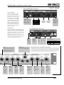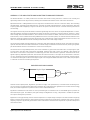
1
230
MASTER voice cHANNEL
Optimized processing for human voice over any medium.
C O M P L E T E V O I C E P R O C E S S I N G SYSTEM
Featu r i n g A p h e x E x c l u s i v e P r o c e s s i n g Te c hnology
•
•
•
•
•
•
•
•
•
•
Low Noise RPA T M Tube Mic Preamplifier
Easyrider T M Compressor
Split Band De-Esser
Logic Assisted Gate T M Noise Gate
Big Bottom® Bass Enhancer
Full Parametric Equalizer Band
Aural Exciter® Intelligibility Enhancer
SPR T M Phase Rotator
High Resolution 24/96 A/D Converter
+4 Balanced and -10 Unbalanced Out p u t s
S Y S T E M S
THE SOLUTION DELIVERY SERIES
Solution Delivery Series
230
Master voice channel
Instruction Manual
P/N 999-4200
Revision 1
Released 05/30/2004
Manufactured by
Aphex Systems Ltd.
11068 Randall St.
Sun Valley, CA 91352
USA
S
Y
S
T
E
M
S
Copyright 2004 Aphex Systems Ltd. All rights reserved.
Produced by: Donn Werrbach. Creation tool: Adobe InDesign 2.0. Printed by: Stuart F. Cooper Co., Los Angeles.
230
instruction Manual
A MESSAGE FROM THE PRESIDENT
Dear Aphex Customer,
Congratulations on your purchase of the Model 230 Master Voice Channel.
Discriminating people have successfully and happily used a combination of Aphex microphone preamplifiers and processing for years even
though it required using different boxes and additional interconnections. The Model 230 combines the proprietary circuits and features that
made those individual products so effective and great sounding along with powerful new proprietary circuits. All these circuits make the
Model 230 the best sounding and most flexible, yet easy to use, voice processor on the market. On air or in the production room voices will
be more intelligible, have greater presence and fullness, and have more consistent levels- all while retaining their unique characteristics.
As with all our products, we are extremely proud of the ingenuity of design and the manufacturing quality of the Model 230. We love to
hear from you, our customers, about your experiences with any of our products. Our customer support is unmatched in the industry, so
please do not hesitate to contact us.
Sincerely,
Marvin Caesar
Safety Declarations
CAUTION: For protection against electric shock, do not remove the cover. No user serviceable parts inside.
WARNING: This equipment has been tested and found to comply with the limits for a Class A digital device pursuant to
Part 15 of the FCC Rules. These limits are designed to provide reasonable protection against harmful interference when
the equipment is operated in a commercial environment. This equipment generates, uses, and can radiate radio frequency
energy and, if not installed and used in accordance with the operating guide, may cause interference to radio communications. Operation of this equipment in a residential area is likely to cause interference in which case the user will be required
to correct the interference at his own expense.
The user is cautioned that changes and modifications made to the equipment without approval of the manufacturer could
void the user’s authority to operate this equipment.
It is suggested that the user use only shielded and grounded cables to ensure compliance with FCC Rules.
|
Page 2
Aphex Systems Ltd. Model 230
Copyright 2004 by Aphex Systems, LTD. All rights reserved. All Aphex products are trademarks or registered trademarks of Aphex Systems, LTD. Other brand and product names are trademarks or registered trademarks of their respective holders.
master voice channel
230
Table of Contents
1.0 CONTROLS & INDICATORS PLUS QUICK
SETUP........................................................................
4
2.0 “MASTER VOICE CHANNEL”- WHAT?
6
3.0 INSTALLATION AND INTERFACING
3.1 Installation ..........................................................................................................................
3.2 Rear Panel View ..................................................................................................................
3.3 AC Line Connection ............................................................................................................
3.4 Mic Input Connections .........................................................................................................
3.5 Insert Jacks...........................................................................................................................
3.6 Output Connections.............................................................................................................
3.7 Digital Audio Outputs .........................................................................................................
3.8 Word Clock .........................................................................................................................
3.8.1 INT/EXT...............................................................................................................
3.8.2 WC IN................................................................................................................
3.8.3 WC OUT.............................................................................................................
3.8.4 Local Clock Mastering.........................................................................................
3.9 Power Supply........................................................................................................................
7
7
7
7
7
8
8
8
8
8
9
9
9
4.0 USING THE 230
4.1 Using the Mic Input..............................................................................................................
4.2 Using Phantom Power...........................................................................................................
4.3 Using the Polarity Switch..... ................................................................................................
4.4 Using the Pad.......................................................................................................................
4.5 Using the Low Cut................................................................................................................
4.6 Reserved ..............................................................................................................................
4.7 Using the Phase Rotator........................................................................................................
4.8 Using the Compressor...........................................................................................................
4.9 Using the Logic Assisted Gate...............................................................................................
4.10 Using the De-esser..............................................................................................................
4.11 Using the Equalizer Block....................................................................................................
4.11.1 Big Bottom........................................................................................................
4.11.2 Parametric Equalizer..........................................................................................
4.11.3 Aural Exciter.....................................................................................................
4.12 Using the Level Control......................................................................................................
4.13 Clip Light...........................................................................................................................
4.14 Digital Outputs..................................................................................................................
10
10
11
11
11
11
12
12
12
13
13
13
13
13
13
13
13
5.0 WARRANTY AND SERVICE
5.1 Limited Warranty ................................................................................................................ 14
5.2 Service Information ............................................................................................................. 14
6.0 SPECIFICATIONS
6.1 General Specifications ......................................................................................................... 15
6.2 Architectural Specifications ................................................................................................. 16
7.0 APPENDICES
Appendix A - Balanced and Unbalanced Lines and Operating Levels ...........................................
Appendix B - Dealing With Ground and Hum ............................................................................
Appendix C - Proper Wiring Techniques ......................................................................................
Appendix D - Standard Cable Wiring .........................................................................................
Appendix E - Back to BASS-ics.....................................................................................................
Appendix G - Helpful Wiring Table... .........................................................................................
Appendix G - Aural Exciter and Big Bottom Technologies Explained.............................................
Aphex Systems Ltd. Model 230
17
18
20
21
25
27
29
Page 3
230
instruction Manual
1.0 Controls and Indicators with Quick Setup
POWER INDICATION
The Aphex logo above the power switch glows yellow during the
tube preamp’s warmup time and green when the unit is ready.
LOW NOISE MIC PRE
The 230 works with all professional microphones. The clean and
stable 48V phantom supply is suitable for even the most expensive microphones. The 12dB/octave low cut filter starts at 70Hz
to effectively reduce wind blast without diminishing voice body.
Included is a selectable phase rotator following the principles of
the Spectral Phase Refractor (SPR) circuit used in our Type III Aural
Exciter and Model 661 Expressor. This helps to make spiky voices
more symmetrical while also adding clarity and body.
COMPRESSOR
The 230 includes a special version of Aphex’s patented Easyrider™
Compressor which has proven to be outstanding for voice work.
It is very simple to use with only two controls: Gain/Drive and
Release. To get deeper compression, turn up more Gain. To
manage the density and loudness, work with Release. Faster is
louder and denser. Slower is more natural and open.
LOGIC ASSISTED GATE™
Another Aphex patent, this noise gate is the most stable gate on
the market. It never hesitates or chatters. Once triggered, even
by a microscopic transient, it progresses fully through the attack,
hold, and release sequence. The attenuation depth and gating
threshold are user adjustable to allow for varying requirements.
The attack, hold, and release timing are internally set to function
optimally on voice waveforms.
POWER INDICATOR
Logo glows yellow during power
on warmup. Preamp output is held
muted. Turns green after warmup
interval. Preamp becomes operational.
POWER
SWITCH
Turns power
on and off.
Page 4
GAIN/DRIVE
Adjusts
preamp gain
and drive into
the compressor.
DE-ESSER
This de-esser is unlike any other. It is more effective and flattering to
voice. Using a split-band technique with Linkwitz-Riley crossovers,
the voice remains bright and sharp, never losing presence while
de-essing. The de-ess threshold control lets you chose the essing
level that you want. Because of sophisticated technology, sibilance
is trapped for all voices. No frequency tuning is necessary.
EQUALIZATION BLOCK
Other voice processors give you several bands of parametric eq
that you must fuss with to find a suitable setting, usually not really
flattering to voice. Instead, the Model 320 gives you the popular
Aphex Big Bottom and Aural Exciter that are proven to not only
flatter voices but increase power, punch and intelligibility. As a real
plus, they are also very easy to adjust. A fully parametric equalizer
band is also provided to handle those annoying frequency anomalies that some voices can contain, or for special effects.
REAR INSERT JACK
Allows you to insert any kind of line level audio equipment into
the signal path between the 230’s dynamics processing and the
equalizer section. The operating level at this jack is in the vicinity of
0dBu. You should set up your inserted outboard gear accordingly.
METER
Either peak output level (relevant to both analog and digital headroom at 0dB = max before clip) or the compressor’s gain reduction
will be shown according to the position of the Meter switch. The
bar graph will move upwards indicating level, and downwards
indicating gain reduction.
48V
When pressed,
turns on the
microphone phantom 48V power
Lo Cut
Switches on
the 70Hz Low
Cut filter.
Invert
Polarity
When
pressed,
inverts the
relative polarity (phase)
of the mic
input.
CLIP/MUTE
Flashes yellow when the
preamp is muted by the
cough switch. Flashes red
indicating clipping.
Phase Rotator
Enables the
Spectral
Phase
Refractor
to improve
speech symmetry.
PAD
When pressed,
turns on the 20dB
input pad.
Compressor
Turns on the
Easyrider
compressor
circuit.
Meter
Indicates
peak output
level or gain
reduction of
the compressor.
GATE THRESHOLD
When the sound is higher than this
level, the gate opens up instantly. No
“chattering” thanks to the patented
Logic Assisted Gate.
RELEASE
Controls the
density of
compression. Slow
for natural
leveling and
fast for more
loudness.
Aphex Systems Ltd. Model 230
GATING
Shows when
the gate
is closed
or closing.
When the
light is off,
the gate is
fully open.
230
master voice channel
Quick Setup
Rear Panel Analog Connections
OUTPUT CONTROL
Once all processing and equalization is set where you want it,
the output level may need to be
adjusted. Do not let the peak
level frequently exceed -6dBFS.
This will make sure the digital
output carries well through subsequent mixing and processing.
When using the analog output,
adjust the level to produce the
desired average output level
(0VU) as seen on the outboard
equipment’s meters.
BALANCED
TRS
MIC INPUT
Works with all standard
microphones, phantom
powered or passive.
Phantom power activated from front panel.
DIGITAL AUDIO
The 230 supplies industry standard stereo
AES/EBU, S/PDIF, and TOSLINK digital audio
outputs. The single mic channel appears
on both stereo channels as a mono signal.
Sample rate and word clock options are all
available at the rear panel. There is no “lock”
indicator per-se, but word clock lock is indicated by the presence of digital audio at the
output. “No output means no lock.”
Line Level
Processor,
i.e.,
Compressor, EQ
DE-ESSING
Shows when
the the deesser is working. When
the light is
on, sibilance
is being
controlled.
DE-ESS
THRESHOLD
Lets you set
the level
where you
want your
esses to level
off.
PARAMETRIC EQ
Works like a standard parametric band
with tune, Q, and boost/cut controls.
BIG-BOTTOM
TUNE
Adjusts the
frequency
below which
enhancement
takes place.
Helps mainly
male voices.
BIG-BOTTOM
MIX
Adjusts the
strength
(boost) of the
Big Bottom
effect.
Aphex Systems Ltd. Model 230
-10dBV
Unbalanced
Output
Rear Panel Digital Connections
AES/EBU
OUTPUT
Digital 110
Ohm cables
only. (Do not
use regular
audio cables.)
DEPTH
Lets you set how much attenuation the
gate will deliver. Use the lowest attenuation that’s needed to reduce room
wetness, breath, or background noise.
Usually 6 to 15dB is sufficient.
+4dBu
Balanced
Output
COUGH SWITCH
Allows you to
silently mute the
output on the
fly using a handheld, desktop, or
floor switch.
S/PDIF &
OPTICAL
OUTPUTS
All outputs are
active at the
same time.
SAMPLE RATE SWITCHES
Rate
44.1
88.2
48
96
Base
44.1
44.1
48
48
Mult
X1
X2
X1
X2
WORD CLOCK
Jack Functions & Signals
Mode
INT
EXT
IN Signal
NONE
EXT CLK IN
OUT Signal
INT CLK OUT
PASS THRU FROM IN
Why You Shouldn’t Connect a 230’s Output to a Mic Level Input.
The bottom line: you will get an unsatisfactory noise level. The Model 230 is designed to generate a line
level output from a mic level input. It optimizes the signal to noise ratio by giving you a strong signal far
above the preamplifier’s basic self noise level. This strong output signal can be up to 65dB higher than
the mic signal. It is perfect for a standard line input of a mixer or console but will overload a mic input. If
you turn down the 230’s output level enough to stop overloading the mic input of your mixer, then your
mixer’s preamp gain will amplify the natural noise floor far too much, causing a noisy signal.
AURAL EXCITER
TUNE
Adjusts frequency
above which
enhancement
takes place.
AURAL EXCITER
MIX
Adjusts the
strength (boost) of
the Aural Exciter
effect.
BB/EQ/AX
ON
Switches the
equalizing
chain in and
out. Provides
full true
bypass of the
circuits.
OUTPUT
Adjusts the
final processed output
level as seen
on the VU
meter.
Page 5
230
instruction Manual
2.0 “Master Voice Channel” - What?
HAVING AN EDGE
Talented people aren’t totally perfect. Well, of course,
you are, but let’s face it -- who else really is? Sometimes it takes an edge for even the best talent to grab
a top position in the industry. Other than having a
well connected agent and a pretty good set of pipes,
the Model 230 might just give you the edge you
need.
GETTING BIG
As you probably already know, getting a really sweet
voice track requires more than the right mic or expert
mic technique. A plain recorded voice can sound very
good alone, but not “have it” when put into the mix.
Voice artists are constantly asked for a more compelling, louder track. TV promos, film trailers, even radio
production voices need to be dense, fat, consistent
and loud. The body of the voice needs to be fuller
- somehow bigger than life. If this is your goal, you
need a Model 230.
WORK, DON’T TWEAK
At some point as a professional you want to stop
fooling with the equipment and concentrate on
reading, talking, and expressing. The Model 230 will
help you do that by giving you easy to use voice processing that works incredibly well without constant
fidgeting.
ARE YOU GEARED OUT TO THE MAX?
For many voicing pros, getting bigger means gathering up countless compressors, limiters, equalizers and
other audio tools in a quest for that certain “sound”.
Managing all that gear can be overwhelming. It
seldom gets used to its full potential. That’s why you
need the comprehensive, easy to use Model 230. It
combines a whole array of proven voice processing
effects with a super quality mic preamp in an easy
to use package. It even gives you digital audio that’s
ready for your hard disk or recorder.
BOOST YOUR ELOQUENCE
For live on-air talent, preachers, lecturers, or anyone
speaking into a microphone, the Model 230 can
make voices at all times clear, compelling and able to
be heard over a world of background chatter. It may
not bestow upon you any new talent of eloquence,
Page 6
but it can give a boost to whatever you’ve already
got.
STAYING IN CONTROL
Radio and TV stations frequently need to better
control live originated voice quality. Making news
anchors, drive-time jocks, spot producers, and everyone else sound more intimate, clear, and regulated is
a big presentation booster.
HANDLING MANY VOICES
When the news team is on the air, or the morning
zoo is hamming it up, all of the voices need to be
balanced and adjusted automatically to make sure
they are heard at a constant level. A Model 230 used
on each microphone will take care of this problem
perfectly. The Logic Assisted Noise Gate will reliably attenuate background noises, crosstalk, and
reverberation when multiple mics are open but not
spoken into.
DE-ESSING, DIGITAL, AND ALL THAT STUFF
There are various channel strips and other processors
with mic preamps on the market. Most contain the
same basic array of effects and controls, but are not
easy to operate effectively. The Model 230 is different.
It contains unique and proprietary effects innovated
by Aphex engineering that are specifically excellent
for maximizing voice quality for both air and production. Plus, it was engineered with intuitive controls
that do not have critical settings. You will find it easy
to understand and use.
Exclusive Aphex Features:
• RPA Tube Preamplifier™
• Easyrider™ Compressor
• Logic Assisted Gate™
• Big Bottom®
• Aural Exciter®
• SPR Spectral Phase Rotator™
Custom Engineered Functions:
• Low Distortion Parametric EQ
• Split Band DE-ESSER
• High Resolution A/D Converter
Aphex Systems Ltd. Model 230
master voice channel
230
3.0 Installation & Interfacing
3.1 INSTALLATION
The Model 230 occupies a single rack space (45mm or 1-3/4 inches) of a standard EIA equipment rack.
When rack mounting, use appropriate cushioned rack screws. Never restrict air flow through the device’s vents.
When installing the units into a rack, distribute the units evenly. Otherwise, hazardous conditions may be created by an uneven weight distribution. Connect the unit only to a properly rated supply circuit. Reliable earthing (grounding) of rack mounted equipment should be maintained. Try not to position the 230 directly above
devices that generate excessive heat such as power amplifiers (unless adequately ventilated) or near equipment
with heavy transformer hum fields.
3.2 REAR PANEL VIEW
3.3 AC LINE CONNECTION
Use only a power cord that carries approvals for use in your location. The 230’s internal power supply is
designed to operate from all nominal power sources from 100 to 240 volts a.c. at 50/60Hz without requiring
the user to change any settings. In case of failure, do not attempt to change the internal fuse because it will
never blow unless the power supply fails catasrophically. The power supply will need to be serviced by a competent service technician in such a case.
3.4 MIC INPUT CONNECTION
The microphone input connector is located on the
rear panel. It is the standard XLR-3F type. Use only
properly wired balanced mic cables.
PROPER MICROPHONE CABLE WIRING
CAUTION
Female XLR
Male XLR
48V
CAUTION: Beware that 48 volt PHANTOM POWER
may be applied to the microphone input, creating a potential shock hazard. Standard practice
dictates shutting off the phantom power before
plugging or unplugging microphones. Wait at
least 10 seconds for the voltage to fall sufficiently.
This is not only for safety, but for protection of
sensitive microphones against power inrush.
Aphex Systems Ltd. Model 230
3.5 INSERT JACKS
The Model 230 allows you to insert additional signal
processing between the 230’s front-end dynamics
processing and the aft-end equalizer block. Both
Send and Return jacks are balanced and run at
approximately 0dBu. This is a perfect place to insert
an external reverb unit or profanity delay. Other than
that, we can think of no external processing that
would be necessary, but you have the option to put
anything there that you wish as long as it returns a
nominal level.
Direct feed-through occurs with the normalling contacts of the jacks. If you plug into either the SEND
or RETURN jack, the internal path is interrupted. You
need to be sure you have a viable send-return circuit
externally or there will be no audio output from the
230.
There is no insert bypass switch. Once plugged in, the
insert is always inserted. If you can’t get any output
from the 230, make sure the inserted gear is operating before you assume the 230 is defective.
Page 7
230
instruction Manual
Installation & Interfacing
3.6 OUTPUT CONNECTORS
There are two output connectors located on the
rear panel: one 1/4” TRS phone type and one XLR3M type. They can be used at the same time to feed
separate equipment.
The output level at the XLR is +4dBu impedance
balanced, while the phone jack runs unbalanced at
-10dBV (consumer level).
If you intend to make an unbalanced output from
the XLR jack, simply take “hot” from pin 2 and
use pin 1 for ground. Leave pin 3 unconnected or
grounded. Never ground pin 2.
Refer to Appendix C & D for more information on the
proper wiring of balanced and unbalanced lines.
DIGITAL OUTPUT DEFINITIONS
XLR: AES/EBU 110Ω @ 5Vp-p
RCA: S/PDIF 75Ω @ 1Vp-p
OPTICAL: Toslink S/PDIF encoded for optical fiber.
3.7 DIGITAL AUDIO OUTPUTS
The processed mic signal is converted to digital in
both channels at equal level as a mono signal. There
is no provision to externally drive one of the A/D Con-
verter inputs.
3.8 WORD CLOCK
3.8.1 INT/EXT
Synchronization is selected by the INT/EXT switch
on the back panel. With external clock, the 230 will
sync to frequencies between 32kHz to 96kHz. With
internal clock, you get the four frequency selections
of 44.1, 48, 88.2 or 96kHz.
3.8.2 WC IN
This BNC jack is provided to receive your master clock
source. It will accept industry standard Word Clock,
from less than 1 to over 5Vp-p pulse amplitude. It
does not accept AES/EBU or Superclock.
The Model 230 can operate equally well from a
typical “brute force” 5V word clock output or from
a matched impedance master clocking distribution.
Please refer to the appendix for a thorough discussion of clock wiring and distribution systems.
When the Model 230 is operating in external clock
mode, the WC IN jack is tied directly to the WC OUT
jack through a metal relay contact. The input impedance is high enough to daisy-chain up to four units
by looping straight through. The final daisy-chained
unit should have a 75 ohm BNC terminator plug
inserted in its WC OUT jack to properly terminate the
transmission line. If only one unit is connected, then
simply place the terminator plug on the single unit’s
Figure 3-1 Daisy Chaining Alternatives for External Master Clock
Universal Technique
230 #1
230 #2
230 #3
230 #4
In
In
In
In
Out
Out
Out
Out
Terminator
Clock Source
Ok For Closely Co-located 230’s
Tee
&
Terminator
230 #1
In
Out
230 #2
230 #3
230 #4
In
In
In
Out
Out
Out
Clock Source
Page 8
Aphex Systems Ltd. Model 230
230
master voice channel
WC OUT jack.
3.8.3 WC OUT
This jack is directly tied to the WC IN jack to facilitate
daisy-chaining multiple units to a master clock source
when the unit is operating in external clock mode.
ACCEPTABLE POWER RANGE
85 to 265V~, 50 to 60Hz
When the Model 230 is operating in internal clock
mode, the WC OUT jack is disconnected from WC IN
and instead is connected to the unit’s internal clock
source. Thus, any Model 230 operating in internal
clock mode can serve as a master clock source when
required. The internal clock is derived from a low jitter
crystal oscillator and is fully competent as a master
clock.
Soft-start, overload foldback limiting, and accrosthe-line voltage spike protection is incorporated to
protect the power supply from damage that might
be caused by component failure or power line disturbances. If the internal fuse blows out, a catastrophic
failure has occurred and simply replacing the fuse will
not fix the problem. Due to the extensive protective
measures used, it is highly unlikely a catastrophic
power supply failure will ever occur. However, if it
does, you should contact the factory or a competent
service technician to affect repairs. There are no user
serviceable parts inside.
3.8.4 Local Clock Mastering
In the absence of a suitable external clock source, you
can use one Model 230 as a clock master and slave
everything else to it. For example, to synchronize a
group of Model 230’s, simply set the first unit to
internal clock mode and all the others to external.
Daisy-chain the WC OUT of the first unit through the
WC IN and WC OUT of the remaining units. This way
all digital audio outputs will be locked together to the
first unit’s clock reference. You can also loop the clock
output of the last unit in line to your digital recorder
or workstation, but remember to terminate the last
unit in line.
3.9 Cough Switch
Voice artists/actors often find it necessary to clear the throat, sip a beverage, or cough during narration.
To hide the fact, a convenient mute
and unmute is needed. Here it is, the
model 230’s Cough Switch! Any type of switch wired
to a mono phone plug will work. Usually, a desktop
box mounted silent pushbutton is preferred, as it can
be accessed most readily. Aphex does not presently
supply the cough switch itself, but one can be easily
fabricated by the installer.
3.9 POWER SUPPLY
The 230 is internally powered from a standard IEC
power receptacle on the rear panel. Be sure you use a
power cord that is approved for use in your jurisdiction.
Figure 3-2 Daisy Chaining the Local Master Clock
Internal
Clock
External
Clock
External
Clock
External
Clock
230 #1
230 #2
230 #3
230 #4
In
In
In
In
Out
Out
Out
Out
Terminate here or continue
coax cable to digital recorder/
daw using a 75Ω termination.
Aphex Systems Ltd. Model 230
Page 9
230
instruction Manual
4.0 Using the 230
FRONT PANEL VIEW
4.1 USING THE MICROPHONE INPUT
The Model 230 is perfect for all types of microphones,
either powered or not. We encourage you to try every
mic you own with the 230.
Many features of the 230 are standard with all professional preamps - polarity - pad - etc. Some features
are unique and we hope you will fully exploit them.
4.2 USING PHANTOM POWER
Active microphones that take power through the
standard mic cable fall into a class called “phantom
powered” mics. The power is called “phantom”
because it rides the mic cable invisibly, without
interfering with the audio signal carried on the same
wires.
The industry standard phantom power source is positive 48 volts d.c. supplied to pins 2 and 3 through
precision low noise 6.81KΩ resistors. You may note
from spec sheets that many mics rated for phantom
power actually run at something less than 48 volts.
For example, the Audio Technica AT3031 small diaphragm condenser mic is rated for 11 to 50 volts at 3
milliamps. On the other hand, the Neumann TLM193
spec sheet states only that the supply voltage should
be 48 +/- 4 volts and the current consumption is not
stated. Don’t let these specifications confuse you.
They all run perfectly well off the standard 48V phantom power source.
For the technically interested, here’s why. The 6.81KΩ
resistors mentioned are shown in figure 4-1 below.
Since the power to the microphone is carried equally
(a requirement carefully observed by all mic manufacturers) on pins 2 and 3, it is like powering the
mic through a single series resistance equal to the
two resistors in parallel, which is a resistance of half,
or 3.405KΩ. A voltage drop will occur across the
series resistance equal to the microphone’s current
consumption times the series resistance. In the case
of the AT3031, consuming 3mA, the drop is .003 X
Page 10
3405 = 10.22 volts. That means the voltage actually appearing on pins 2 and 3 is 48 - 10.22 = 37.78
volts. That is why, if you use a voltmeter to check
phantom power while the mic is plugged in, you will
always see something less than 48 volts. This is not a
fault with the mic preamp.
Plugging and Unplugging a microphone when
phantom power is switched on can sometimes be
dangerous. Some microphones can be damaged by
48 V.D.C.
SUPPLY
+
6.81KΩ
1%
2
1
6.81KΩ
1%
PREAMP
3
Figure 4-1 Phantom Powering
power inrush. Good practice calls for switching off
the phantom power before changing or inserting a
microphone. Wait long enough to hear the mic go
silent before unplugging.
You should be aware of the shock hazard with the
phantom power system. Long, open mic cables that
are disconnected from the preamp while phantom is
on can hold a d.c. charge for long periods of time,
sometimes days, weeks or months. They will act as
a storage capacitor and you can get shocked most
rudely by holding the XLR plug and touching the
pins inside. Also beware of microphone patch bays
that may carry phantom voltage. Don’t hold the
patch cord by the metal parts, only the plastic shell.
Aphex Systems Ltd. Model 230
230
master voice channel
Another time when phase reversing can be helpful is
in mixing multiple microphones that are within each
other’s coverage areas. The “crosstalk” between mics
may come through different delays due to the differing distances from the sound. These sounds may
tend to cancel out in the mix. You may get a “nasal”
or hollow effect when all mics are on. Changing the
polarity of one or more mics will often clear up the
problem. It is always worth the time to experiment
with mic polarity.
Distance
to Mic2
Distance
to Mic1
4.5 USING LOW CUT
In the practical world, mics pick up all sorts of
unwanted low frequencies such as hand noise, wind
rumble, or lectern thumps. We designed into the
230 a very effective way of cutting out these low
frequencies while maintaining a sense of normal low
end response. Switching on the LOW CUT FILTER rolls
off all frequencies below 70Hz at 12dB per octave
but places a slight compensation around 120Hz to
improve the low end phase distortion and perception
of remaining bass. We first offered this cutoff shape
with our Model 107 tube mic preamp and it received
tremendous acclaim from vocalists and recordists
alike. So, not wanting to waste a good thing, we carried it forward to the Model 230.
Figure 4-3 LO CUT Response
5
0
Response, dB
4.3 USING THE POLARITY SWITCH
There will be times when you need to reverse the
polarity (phase) of a mic signal. Vocalists monitoring themselves on headphones will hear a different
sound when the phase is reversed. The reversed
phase may sound fuller and more truthful or hollow
and far away. That is because there is a cancellation
of frequencies within the ear when the external sound
from the headphone mixes with the sound directly
conducted to the ear. “Flipping the phase” can make
the problem either more or less noticeable.
-5
-10
-15
-20
-25
-30
20
100
1K
2K
Frequency, Hz
4.6 Reserved
Sound
= Cancelled
Figure 4-2 Phase Cancellation Effect
4.4 USING THE PAD
An input pad is nothing more than a resistive
attenuator that drops the level coming from the
microphone. Its purpose is to give you a way of
preventing overload of the preamp when incoming
signals become excessive.
In the 230, we provided a pad of 20dB. That means
when the pad is on, the net gain of the preamp is
20dB lower than normal. You will almost never need
the pad for voice work. However, if you have brought
the GAIN all the way down and you still have an
excessive level then switch on the pad. You can then
readjust the gain as desired.
Aphex Systems Ltd. Model 230
4.7 USING THE PHASE ROTATOR
The 230’s phase rotator is designed to help reduce
high assymmetric peaks that often occur with voice
waves. By reducing the amplitude of assymmetric
peaks, and making the wave more symmetrical,
the voice can ride louder through compressors and
limiters. This is accomplished by displacing the time
relationship of even harmonics to their fundamentals. Thus, it is called a “Phase Rotator” or a “Phase
Scrambler”.
Although the intent of phase rotating is to symmetrify a voice wave, we have also discovered a
psychoacoustic effect that can take place. By using a
certain tuning of a 4th order all-pass filter, we found
that not only can voice symmetry improve, but sonic
clarity also improves. It’s like adding an extention to
the top and bottom end of the sound spectrum. We
introduced this effect with our SPR (Spectral Phase
Refractor) in previous Aphex products. Many people
Page 11
230
instruction Manual
Using the 230
have remarked about how much better voice tracks
ride over the mix, and how much fuller and deeper
they seem with the SPR. There is no actual frequency
response alteration. It is all in the ear, but it works.
The amount of effect varies from none to a lot
depending on the voice and the sound medium. You
just need to try it to see.
Some words of advice: When doing voice work
while wearing headphones, the Phase Rotator will
affect how you hear yourself far more than it actually
alters your voice. That’s because the body-conducted
sound mixes with the sound from the “cans”. When
the two sounds are out of phase, there will be partial
to full cancellation at various frequencies. Just as you
experience the effect of switching polarity, turning
on the phase rotator will have a pronounced effect.
You should evaluate the phase rotator by auditioning
recorded tracks made with and without the rotator
effect.
4.8 USING THE COMPRESSOR
The 230’s compressor is probably the simplest one
to use that you will ever see. Nevertheless, it is more
sophisticated than compressors with many more controls. The Easyrider compression algorithm automatically adapts to voice waves in a manner that greatly
reduces any pumping effect while it tightens the
average level very flatteringly.
There is only one obvious control: RELEASE. However,
the mic pre’s GAIN control doubles as the compression drive adjustment. To get more compression
depth, run up more gain. The RELEASE control allows
you to chose the aggressiveness of the compression.
For thick and loud, go faster. For more natural and
“open”, go slower.
The gain reduction is displayed on the 230’s 10 segment bargraph meter when the METER switch is
depressed.
When considering how much gain reduction you
should use, take into account your purpose. If the
230 is used for close-miked production, then set up
the gain reduction as lightly as is needed to get a
punchy track. If the 230 is for the on-air studio, then
you might want to max out the gain reduction to
allow for wandering jocks that don’t constantly stay
“on mic”. Running higher GAIN/DRIVE will, of course,
raise the background noise when the compression is
Page 12
released. This can be somewhat mitigated by using
the Gate, but don’t expect too much. The Gate does
its best work when the compression drive is moderate, as with close-miking uses.
4.9 USING THE LOGIC ASSISTED GATE
If you’ve worked with gates before, you probably
know how frustrating they can be, especially with
voice work. Finding the threshold and attack setting that doesn’t clip the first sound and still reliably
gates out the noise is usually difficult and the settings
are unstable. Aphex’s Logic Assisted Gate solves all
that for you very simply. The 230’s gate trigger is
absolutely positive because it’s independent from
the energy content of the sound peak. The slightest
tickling of the threshold by the soundwave triggers
a chain reaction that forces the gate’s attack-holdrelease sequences to perform completely and repeatably. That makes finding the right threshold fast and
easy. The attack, hold, and release timing have been
pre-optimized for voice. All you need to set are the
threshold and depth of gating.
You will probably find the depth of gating is not really
critical for most purposes. However, here are a few
suggestions about setting it. If you want complete
silence between phrases, then use the maximum
depth. However, if you simply want to bring down
ambience pickup as with multiple open mics in a
room, then use minimal depth. That will guarantee that at least some of the talker’s voice will get
through even if the talk level is too low to trigger
the gate. When the gate is closed or closing (blocking), the LED indicator is lit. When it is open (passing
audio), the LED is dark.
4.10 USING THE DE-ESSER
Sometimes you really need this function. Certain mics
are too harsh in the upper range and some voices
tend to whistle or splatter. We have found that the
sibilance frequency range centers around either 6kHz
or 10kHz depending on the voice. Conventional deessers simply detect the presence of any frequency
above some tuning point and duck the whole voice
signal accordingly. This technique is readily adaptable
to a standard limiter, and that is why you generally
find de-essers associated with another limiter function, and not standing alone.
The 230’s de-esser is different. First, it is not associated with another limiter. It stands alone. Secondly,
Aphex Systems Ltd. Model 230
master voice channel
it uses split band techniques to attenuate only the
sibilance, while leaving the body of the voice alone.
Operation of the de-esser is simple. Just set the
threshold to the point where you want the esses to
limit out. Reducing the threshold setting brings down
the level of the esses dynamically. In other words, it’s
like an automatic downward shelving equalizer. It
stays flat until the ess level gets too high and then
introduces the shelf at the level needed to limit the
sound to the threshold level. It has internally set
attack and release characteristics that are optimum
for voice sibilance control. When there is de-essing,
the LED is lit.
4.11 USING THE EQUALIZER BLOCK
Once the voice signal passes through the dynamics
processing, i.e., the compressor, gate and de-esser,
it encounters the three equalizer elements. The first
element of is the Big Bottom low frequency enhancer.
Next is a parametric peak/dip section, and last is the
Aural Exciter top end enhancer. The whole block is
bypassable by the BB/EQ/AX on/off pushbutton.
4.11.1 Big Bottom
Some voices have no low bottom end. In such cases,
the Big Bottom won’t synthesyze a new low end for
you and should not be used. However, voices that
contain a deep chest resonance can be augmented
by the Big Bottom.
Start by turning up the BB Mix to 12:00. Then adjust
the BB Tune to find a frequency that lifts the bottom
without adding a muddy quality. Last, reduce the BB
Mix until just the right touch of bass enhancement
is felt.
230
bandwidth by lowering the Q to properly reduce the
annoyance.
4.11.3 Aural Exciter
Clarity, presence, and loudness can all be enhanced
by the Aural Exciter.
First start with the AX Mix at 12:00. Next, sweep
the Tune to find the best tonal balance. Presence is
best augmented with lower tunes. Air is added with
higher tunes. Finally, readjust the AX MIx for just the
right amount of brilliance. Always err on the conservative side. Use the in/out switch to compare the
plain signal to the enhanced in order to keep from
getting carried away with the effects.
4.12 USING THE LEVEL CONTROL
Once all the processing is adjusted the way you want
it, the output level may be a little high or low. Switch
the front panel meter to PK and adjust the LEVEL
control to obtain peaks that don’t go above -6dBFS.
Alternately, set the LEVEL for 0VU on your console or
recorder’s analog meter.
4.13 CLIP/MUTE LIGHT
If the LED is flashing RED, then the internal operating
level is too hot. This can only occur if the insert return
signal is too hot or if the parametric equalizer is
boosted way too much. This same LED will also flash
yellow while the model 230 is in the MUTED state
activated by the COUGH SWITCH (rear panel jack).
4.14 USING THE DIGITAL OUTPUT
Refer to the installation guide for setting up the
sample rate and word clock options.
4.11.2 Parametric Equalizer
This is a familiar and conventional EQ section. You
can vary the peak/dip frequency, bandwidth and
magnitude. Parametric Equalizers are best used to
dip out annoying sounds rather than trying to peak
up what’s lacking. The Big Bottom and Aural Exciter
are much better at augmentation.
Usually the easiest way to use the parametric is to
first set the Q to a high value (narrow bandwidth)
and set the boost to full up. Then, sweep the frequency until you identify the sound that is annoying.
Then, dip the sound out. You may need to widen the
Aphex Systems Ltd. Model 230
Page 13
230
instruction Manual
5.0 Warranty & Service
5.1 Limited Warranty
PERIOD
One year from date of purchase
SCOPE
All defects in workmanship and materials. The following are not covered:
a. Voltage conversions
b. Units on which the serial number has been defaced, modified, or removed
c. Damage or deterioration:
1. Resulting from installation and/or removal of the unit.
2. Resulting from accident, misuse, abuse, neglect, unauthorized product modification or failure to
follow instructions contained in the User’s Manual.
3. Resulting from repair or attempted repair by anyone not authorized by Aphex Systems.
4. Occurring from shipping (claims must be presented to shipper).
WHO IS PROTECTED
This warranty will be enforceable by the original purchaser and by any subsequent owner(s) during the warranty
period, so long as a copy of the original Bill of Sale is submitted whenever warranty service is required.
WHAT WE WILL PAY FOR
We will pay for all labor and material expenses for covered items. We will pay return shipping charges if the
repairs are covered by the warranty.
LIMITATION OF WARRANTY
No warranty is made, either expressed or implied, as to the merchantability and fitness for any particular purpose. Any and all warranties are limited to the duration of the warranty stated above.
EXCLUSION OF CERTAIN DAMAGES
Aphex Systems’ liability for any defective unit is limited to the repair or replacement of said unit, at our option,
and shall not include damages of any other kind, whether incidental, consequential, or otherwise.
Some States do not allow limitations on how long an implied warranty lasts and/or do not allow the exclusion
or limitation of incidental or consequential damages, so the above limitations and exclusions may not apply to
you.
This warranty gives you specific legal rights, and you may also have other rights which vary from State to State.
5.2 SERVICE INFORMATION
If it becomes necessary to return this unit for repair, you must first contact Aphex Systems, Ltd. for a Return
Authorization (RMA number), which will need to be included with your shipment for proper identification. If
available, repack this unit in its original carton and packing material. Otherwise, pack the equipment in a strong
carton containing at least 2 inches of padding on all sides. Be sure the unit cannot shift around inside the
carton. Include a letter explaining the symptoms and/or defect(s). Be sure to reference the RMA number in your
letter and mark the RMA number on the outside of the carton. If you believe the problem should be covered
under the terms of the warranty, you must also include proof of purchase. Insure your shipment and send it
to:
Aphex Systems, Ltd.
11068 Randall Street
Sun Valley, CA. 91352
PH: (818) 767-2929 FAX: (818) 767 -2641
Page 14
Aphex Systems Ltd. Model 230
230
master voice channel
6.0 Specifications
6.1 GENERAL SPECIFICATIONS
MIC INPUT
Connector:
Type:
Input Z:
Maximum Input Level (MIL):
CMRR:
Nominal Preamp Gain:
Phantom Power:
Pad:
EIN:
Tube Type:
XLR-3F
Transformerless, NPN active balanced, tube second stage
2KΩ nominal
0dBu
Greater than 70dB @ 60Hz
20 to 65dB
+48VDC
20dB
-127dBu (Input Shorted)
12AT7/ECC81 Dual Triode
OUTPUT
Connector:
Type:
Output Z Balanced:
Output Z Unbalanced:
Nominal Level
Maximum Output Level (MOL):
XLR-3M and TRS 1/4” phone jack
XLR is Impedance Balanced (may be used unbalanced); TRS is unbalanced.
XLR: 66Ω
XLR: 33Ω − TRS: 600Ω
XLR: +4dBu; TRS: -10dBV
XLR: +25dBu Unloaded; TRS: +11dBV
COMPRESSOR
Attack/Release:
Ratio:
Threshold:
Knee:
Program dependent, user variable release baseline.
4:1
Fixed
Medium Hard
GATE
Attack:
Hold/Release:
Threshold:
Depth:
0.1 millisecond
300 milliseconds/400 milliseconds
Variable -50 to +20dB
Variable, 1 to 58dB
DE-ESSER
Attack:
Release:
Threshold:
Raio:
Active Band:
0.1 millisecond
100 milliseconds
Variable -20 to +20dB
5:1
4.KHz to 20KHz Linkwitz-Riley 24dB/octave crossover
INSERT
Connector Type Send:
Connector Type Return:
Nominal Operating Level:
Point of Insertion:
1/4” TRS Phone Jack, Balanced
1/4” TRS Phone Jack, Balanced
0dBu
Between dynamics processing and equalizers.
BIG BOTTOM
Frequency Tune:
MIx:
50Hz to 280Hz
OFF to +12dB
Frequency Tune:
Peak/Dip:
Q Range:
240Hz to 8KHz
+/- 12dB
0.5 to 5
Frequency Tune:
Mix:
500Hz to 5KHz
OFF to +12dB
PARAMETRIC EQ
AURAL EXCITER
ANALOG AUDIO
THD:
IMD:
Freq Resp (FLAT):
<.01% @ +4dBu Out
<.01% @ +4dBu Out
18Hz to 24KHz +/- 1dB
DIGITAL AUDIO
Internal Sample Rates:
External Sample Rates:
Resolution:
Word Clock Input:
Word Clock Output:
Dynamic Range:
Noise Dither:
Level Equivalency:
OTHER SPECS
Power requirements:
Power Consumption (maximum):
Dimensions:
Depth Behind Front Panel:
Net Weight:
Shipping Weight:
44.1KHz, 48KHz, 88.2KHz, 96KHz
Automatically syncs to any word clock between 32KHz and 96KHz
24 Bits
BNC Jack, High Z, Captures <1Vp-p to 5Vp-p
BNC Jack, 75 Ohms, 5Vp-p
Digital dynamic range greater than analog front end.
Dithered by analog preamp noise floor. Equivalent to 16-bit digital audio dither.
-20dBFS Digital = +4dBu Analog
85 to 260V~, 50-60Hz
12 Watts
19” W x 1.75” H x 8.25” overall depth (482.6mm W x 445mm H x 209.6mm overall depth)
7.5” (190.5mm)
Rack-mounted: 6lbs. (2.73kg)
9lbs. (4.1kg)
All specifications are subject to change without notice.
Aphex Systems Ltd. Model 230
Page 15
230
instruction Manual
Specifications
6.2 ARCHITECTURAL SPECIFICATIONS
Basic Description
A single channel voice processor comprising a transformerless tube-type microphone preamp, a dynamics processing section and a tone controlling section, in that order. An insertion path shall be provided between the
dynamics procesisng section and the tone controlling section.
The microphone preamp shall comprise the following selectable functions: 1.) +48VDC Phantom Power; 2.)
Polarity Reversal; 3.) Selectable 20dB Pad; 4.) Selectable 70Hz 12dB/Octave Low Cut Filter; 5.) Continuous Gain
Control; 6.) Phase Rotator.
The dynamics processing section shall comprise a voice adaptive dynamic range compressor, a logic assisted
noise gate, and a split-band de-esser.
The tone control section shall comprise a Big-Bottom bass enhancer, an Aural Exciter intelligibility enhancer,
and a single band parametric equalizer.
Physical Properties
The device shall be packaged in an all metal chassis measuring 19” (482.23mm) wide, 1.75” (44.42mm) high,
with an overall depth of 8.25” (210mm). Depth behind the front panel shall be approximately 7” (178mm).
The device shall have a net weight of approximately 6lbs. (2.73kg) and is capable of mounting in a standard
electronic equipment rack.
Power
The unit shall have a self contained power supply operating from the ac line. Primary voltage, connectorization
and agency listings shall be appropriate to meet local requirements.
Page 16
Aphex Systems Ltd. Model 230
master voice channel
230
7.0 Appendices
Appendix A: Balanced and Unbalanced
Lines and Operating Levels
Interfacing all types of equipment with balanced
and unbalanced lines and can sometimes be troublesome. First you have to somehow connect balanced
to unbalanced and then you have to deal with different levels. This tutorial will teach you about the
principles of balanced and unbalanced lines, wiring
standards, and how to effectively interface them.
Standards
Professional audio equipment usually comes equipped
with inputs and outputs that are balanced using
3-pin XLR connectors and sometimes 1/4 inch phone
jacks as well. This equipment most often is designed
to operate at +4dBu, a professional industry standard. That translates to a magnitude of 1.23 volts
RMS (Root-Mean-Squared).
wire is the source and which is the return alternates
accordingly. In this regard, balanced and unbalanced
lines are the same. They both need two conductors.
What makes a system unbalanced is when one of
the wires is formed into a tube that wraps around
the other conductor, without touching it, such that
the outer conductor can be said to “shield” the inner
conductor. This describes all of the coaxial cable used
for video, cable-TV and radio as well as most of the
high fidelity audio cables.
Figure 1 Balanced Line Model
Consumer gear has unbalanced I/O as standard, usually on RCA jacks. The normal operating signal level
follows the IHF (Institute of High Fidelity) standard of
-10dBV, or 0.316 volts (316mV) RMS. Converting to
dBu dimensions, this works out to be the same as
-7.79dBu. There is therefore a difference of 11.79dB
between pro and consumer operating levels.
Grounding
There is the notion that some king of earthly “ground”
exists out there that sinks all the noise and acts as
some kind of a shield. You see wires connected to
ground rods and water pipes that are supposed to
get a good ground. This is not a correct interpretation of grounding from an audio standpoint. Proper
grounding of equipment and wiring is important and
you will gain a better understanding of that as you
read along.
Balanced -vs- Unbalanced
Every audio signal is connected through a circuit. The
circuit must contain two conductors to create a complete return path. In other words, a signal voltage is
conducted to a piece of equipment by injecting a current into a wire. That current has flow though to the
destination through the wire and return back to the
source through another wire. Since audio is an alternating voltage, swinging through negative and positive polarity, the current through the two conductors
changes direction each alternate half cycle. Which
Aphex Systems Ltd. Model 230
Figure 2 Unbalanced Line Model
Balancing
If both conductors are identical insulated wires that
are twisted together, then they form a balanced line.
This describes telephone lines, microphone cables,
and most professional audio cables. Typical balanced
cables include an additional shield wrap around the
twisted pair, but this is not strictly required for balanced lines to work properly.
Many people, because they have more experience
with unbalanced wiring, think that balanced is confusing. Believe it or not, balanced lines are really
easier to understand than unbalanced. There is no
grounding issue with balanced, and the way it works
is perfectly natural and simple. Balancing naturally
rejects hum and noise and eliminates all sorts of complications in interfacing.
Balanced transmission works something like this.
Page 17
230
instruction Manual
Appendices
Your balanced input stage looks at the two wires
and detects only the potential (voltage) difference
between them. Anything that is the same on the two
wires (for all practical purposes as seen measuring
from ground) is called a common mode signal and
is cancelled out by the differential amplifier. Figure
1 illustrates how the hum is induced into both wires
equally and therefore is cancelled out.
Since the balanced line has wires that are twisted
together, each wire tends to pick up the same amount
of induction from external sources. Induction will
create no significant voltage difference between the
wires, hence the noise (or hum) will not be picked up
by the differential input stage.
It can be seen that the signal generator driving the
twisted pair will cause a difference between the wires,
and that signal will be readily picked up by the differential input stage. One of the beauties of the balanced line is that it is completely independent from
ground. Nothing is connected to ground at all, nor
does it care about ground. Nevertheless, most professional cable has an overall shield wrap that is
intended to be connected somehow to ground. You
may well ask why, and the answer is less than glorious. Simply, nothing is perfect, not even balanced
cable. Under some circumstances the shield can overcome extreme interference problems that can’t be
adequately rejected by the twisted pair alone. Things
like 2-way radios, television transmitters, and light
dimmers can induce very heavy interference that may
be reduced by shielding. You are going to find virtually all balanced cables include a shield so you need
to deal with it, even if it is not actually needed. That
subject will be addressed a little later.
Unbalancing
Unbalanced wiring works a little differently. Figure 2
shows the basic plan. In this case, the wires are not
twisted, they are coaxial. The unbalanced input stage
is somewhat like the balanced input stage because
amplifies a difference signal, but this time it is the difference between two non-symmetrical conductors.
To make things even less symmetrical, the outer conductor is connected to ground at both ends. The
principle is that the outer shield conductor shields
the inner conductor from induced noises. This can
only work well if the cable is relatively short and
the ground at each end of the cable is somewhat
Page 18
equal, i.e., there is no “grounding difference” that
can cause current to flow through the shield conductor. Grounding difference is a serious problem in
studios, because often the equipment grounds are
connected to power outlet grounds, and there can be
a significant difference of ac voltage between alternating wall outlet grounds. For this reason, unbalanced systems can sometimes never be made hum
free, and just changing one piece of equipment in
a studio can cause hum to appear somewhere else.
When you are using unbalanced gear, it is a very
good procedure to power all your equipment from
one large power isolation transformer. At the very
least, make sure all equipment is powered together
off the same distribution panel circuit (same circuit
breaker).
Appendix B: Dealing With Grounds and
Hum
Ground Loops
Many people equate this term with hum, and that’s
just about the bottom line of it. If you have a ground
sensitive system, like unbalanced audio equipment
for example, then hum will result from ground
currents that flow from the ac power system. It is
sometimes very difficult to isolate and stop ground
currents between unbalanced equipment, but it is
quite easy to clean up balanced gear. That’s why pro
gear is always balanced! The cost of balancing is that
of more expensive connectors, cable, and electronics
but the cost is worth it when you depend on your
audio quality. That’s why the Model 230 is equipped
with a fully balanced I/O. Now that we’ve sold you
on only using really expensive pro gear, lets show you
how to get away with the really cheap stuff! At least
from the standpoint of killing ground hum.
A ground loop is an ac current that has become
routed through your audio ground system. The current comes mainly from ground potential differences
that exist between different wall outlets that return
to opposite phases at the power distribution panel.
Secondarily, however, many pieces of equipment contain line filters and transformers that leak a small
amount of ac power into the chassis and ground
return.
You may once have had the experience of getting
zapped by touching two pieces of gear at the same
Aphex Systems Ltd. Model 230
master voice channel
230
6.0 Appendices
time. That illustrated the ground loop effect - straight through you! No matter what you do, you
may not be able to prevent some of your equipment
from generating ground currents. The most likely
culprits are digital products because they use switching power supplies that require heavy line filters to
prevent conducted EMI from going out of the box.
Filters so employed very often take the ground leakage current right up to the UL safety limits. Although
it won’t kill you, that is a lot of ground loop current
for audio cables to handle.
There are basically three ways to attack the problem
of a ground loop. First is to eliminate it from its
source, and the second is to re-route it through
another path. The third is to balance out your unbalanced audio interfaces.
Identify the Sources
A good way to identify grounding problems is to use
a multimeter to check the ac voltage between the
chassis of your various gear when no audio cables are
hooked up and all gear is plugged in and switched
on. Just start touching the two probes to the metal
chassis of different pieces of gear. Ideally, you should
always see zero volts. Warning! You may see as much
as the whole line voltage between two different chassis! It does happen. This voltage between chassis will
be responsible for your ground loop problems. If
you find there is more than about 1 volt between
equipment grounds, you should start looking for a
remedy.
Commonize the Power
Try plugging all of your equipment into the same
outlet strip. Get one that has enough outlets in one
strip or string more than one together. Of course, you
need to make sure you don’t overload the one ac circuit your strip is plugged into. If the load is too great
for one circuit, use a second or third circuit that is
tapped off the same 120 volt phase in your distribution panel. That means all outlets should be on odd
or even numbered circuit breakers. That’s because,
as you go down the column, the circuit breakers
tap into alternating legs of your incoming electric
power. Be sure you’re always on the same leg. You
can tell you’re on the same leg by measuring the ac
voltage between the hot slots of the different outlets
you’ve chosen. It should be very low or zero. That will
remedy 50 percent of the cases.
Aphex Systems Ltd. Model 230
Check the Cord Polarity
For products that have 2-wire power cords, try reversing one of the power cords in the socket. That may
reduce the ground current generated by the internal
electronics of the offending gear.
Redirect Ground Loops
Sometimes it just comes down to brute force grounding. That means providing such heavy, low resistance,
ground current paths that little current is left to flow
through your audio grounds. You can try adding
heavy gauge, for example 12 gauge, copper wire
from chassis to chassis. You will need to locate a
metal screw that solidly binds to the metal chassis of
the gear. You may even need to drill a hole through
the chassis and install a screw yourself. Equipment in
rack shelves can have their chassis grounded to the
metal rack frame by a heavy wire and the frame itself
can act as a brute force ground. You just have to try
everything you can think of. Usually a combination of
all these methods will be needed to completely clean
up a badly humming audio system.
Balance Out the Audio
Remember, balanced lines are inherently hum free.
If you can balance out your unbalanced equipment,
you will be able to stop the hum.
Pseudo Balancing
You will find in Appendix D an interconnecting
method called Pseudo Balanced. This works when
connecting an unbalanced output to a balanced
input. This breaks up the ground loop by requiring
the shield to be grounded only at one end. For best
results always ground the shield only at the receiving
end.
Level Interface Units
Aphex manufactures the Model 124 Level Interface
box which is designed to electronically convert two
unbalanced inputs and outputs into two balanced
inputs and outputs, and at the same time translate
the -10dBV IHF unbalanced levels to the pro +4dBu
balanced levels. This cost effectively gives your nonprofessional unbalanced equipment a fully professional I/O equal to the world’s best pro audio gear.
Seriously consider putting one of these on each
unbalanced piece of gear you use.
Page 19
230
instruction Manual
Appendices
Avoid Transformers
The use of balancing transformers is an option, but
you will invariably lose audio quality due to transformer limitations. Try everything else first.
Appendix C: Proper Wiring Techniques
A true balanced line should be used wherever your
equipment allows. Use “twisted pair” shielded cable.
For unbalanced wiring you should use high grade,
low capacitance shielded wire for best results. If you
have an unbalanced output but have a balanced
input, the “pseudo-balanced” configuration may help
deal with ground loop hum. This method and others
are illustrated in Table 2.
CONNECTOR WIRING STANDARDS
The 3 pin XLR, 1/4” (63.5 mm) TS mono phone and
the 1/4” (63.5 mm) TRS stereo phone are the most
commonly used line level connectors in pro audio.
Less common is the use of the “RCA” phono jack,
which is essentially a consumer type connector. The
XLR and the TRS are three conductor and are used for
balanced connections. The TS and the RCA are two
conductor and are used for unbalanced connections.
In addition to the three main contacts on an XLR
there is also a grounding lug contact. This lug is connected to the connector’s case (shell). In all Aphex
products audio ground and chassis ground are one
and the same. Aphex products that use XLR connectors tie Pin I to the XLR case automatically. Therefore it is not necessary to use the XLR case-ground lug.
This also makes possible the use of XLR ground drop
adapters (see Note 3).
TABLE 1: The wiring convention shown is now standardized in 17 countries including the USA. Please
note that any equipment that still uses Pin 3 as positive on XLR connectors is not adhering to the standard.
THE PIN 1 DILEMMA AND HOW IT AFFECTS CABLE
SHIELD CONNECTIONS
The three main contacts on an XLR (or TRS) and
the accepted wiring assignments shown above are
Page 20
only part of the picture. The standard for terminating ground is Pin 1 (Sleeve). But which ground? It
could be connected to audio signal ground or chassis
ground depending on the method of grounding used
by the equipment manufacturer. In all Aphex products audio ground and chassis ground are one and
the same at all I/O jacks. This is just good, common
sense engineering practice (which is what you would
expect from us, course). Unfortunately, many products are designed so that the noisy currents from
the shield drain into signal ground instead of chassis ground. This practice creates a real hum and
noise problem for end-users. The appropriate overall
grounding scheme of an audio system would be a lot
easier to predict without this problem1.
The standard balanced line wiring recommendation
from Aphex Engineering is this: In the majority of
cases maximum noise rejection occurs when the
shield is connected to the input ground only (especially in locations with high levels of RFI). That means
the sending end shield should be left disconnected.
However, if you already have cables with the shield
connected at both ends, go ahead and try them
out. If you are connecting a fairly simple audio
system it may be fine as is.
R
A word on optional shield connections: Connecting the cable shield of a balanced line at both ends
creates unnecessary ground loops which may carry
noise and hum currents that can be amplified. Connecting the shield only at the sending end (instead
of the receiving end) may exaggerate common mode
noises at the receiving input stage. It can actually
increase RFI and noise more than having no shield
at all. Because of the “Pin I Dilemma” (mentioned
above) you may be forced, in some situations, to
experiment with how the cable shield is connected
to ground to eliminate a pesky hum or radio interference problem. It might be good to try XLR ground
drop adapters (see Note 3) as a method of trying
these conflicting methods out and being able to
change easily if necessary.
R
IMPEDANCE
Regardless of inaccuracies, it has become more or
less standard over the years to refer to balanced
Aphex Systems Ltd. Model 230
230
master voice channel
Appendices
TABLE 1 - BALANCED & UNBALANCED CONNECTOR WIRING STANDARDS
3-Pin XLR
1/4” TRS Phone
Standard Wiring Convention (Balanced)
Pin-1
Sleeve
Ground/Shield (Earth, Screen)
Pin-2
Tip
Positive (Signal, High, Hot)
Pin-3
Ring
Negative (Signal Reference, Return, Low, Common)
1/4” TS Phone
RCA
Standard Wiring Convention (Unbalanced)
Tip
Center Pin
Positive (Signal)
Sleeve
Shell
Ground/Shield (Signal Reference/Return)
lines as low impedance and unbalanced lines as high
impedance. The fact is, however, that both balanced
and unbalanced lines are operated at low impedance in modern practice owing to the fact that all
output stages have become low impedance. A few
exceptions might be outputs from passive mixers,
instrument pickups, electric guitars and some keyboard synthesizers. It is generally ideal to drive any
audio line from a low impedance and receive into a
high impedance. Generally, a minimum 1: 10 ratio is
possible. This is called “bridging”. This has become
modern practice and all balanced inputs are normally
running 10K ohms or higher impedance. Because of
these developments, it is now no longer as critical to
consider impedance when dealing with interfacing
pro line level equipment (impedance “matching” is
mostly a requirement of the past).
A word on impedance and interfacing adapters:
If you are connecting between two line level devices
and they have different connectors (example: 1/4”
phone to XLR or vice-versa), you do not need to use
an impedance matching transformer. With very few
exceptions you are strictly dealing with a difference
in connector types and should only use hard-wired
adapters (or cables) for this situation.
APPENDIX D: Standard Cable Wiring
In relation to 1/4” phone jacks, you may see the terms
“TS” and “TRS” as abbreviations. Here is a what that
Aphex Systems Ltd. Model 230
means: TS refers to the Tip-Sleeve or “mono” 2conductor type and TRS refers to Tip-Ring-Sleeve or
“stereo” 3 conductor type 1/4” phone connectors.
This applies to jacks (female connectors) and plugs
(male connectors).
Note: We recommend using only conventional
1/4” phone plugs with the Model 230 and with
all other audio equipment. Professional patch bay
cords using brass PJ055 telephone type plugs are
designed only for patch bays and will not make
proper contact with standard 1/4” phone jacks.
The following instructions show all the different ways
you will probably ever need to hook up your 230 as
well as any other equipment you may own. You will
see that connecting balanced outputs to balanced
inputs is ultimately simple and the same cable will
work for all flavors of output stages.
Connecting a balanced output to an unbalanced
input requires a little more knowledge and care.
You should refer to your equipment manuals and
determine the type of balanced output stage that is
provided, then use the correct “transition cable” as
depicted in this section. Improper transition cables
can cause crosstalk, hum, and distortion problems
within your system.
TYPES OF BALANCED OUTPUTS
Believe it or not, there are at least 5 types of balanced
output stages in use today. They may be placed
into two main classes: transformer balanced, and
Page 21
R
230
instruction Manual
Appendices
transformerless balanced, usually called “active balanced”. Transformer balanced outputs are becoming
outdated because of their high cost and their sonic
limitations. However, they can still be found on a lot
of older equipment.
Within the transformerless class, there are several
types of circuits that are used by different manufacturers. These different types of output circuits all look
just about alike to any balanced line, but they act differently when driving an unbalanced line. You need
to observe the proper cable wiring for each type of
output circuit. We strongly recommend that you refer
to your various equipment manuals to find out what
is used in each case before hooking up to unbalanced
lines.
R
When connecting a balanced output to a balanced
input, however, you don’t need to know what kind
of balanced output you are dealing with. Simply
treat it generically.
XLR to XLR
OK for Microphones
Standard store-bought cable. Shield grounded at both ends.
Positives: Good for microphones.
Negatives: May cause ground loops through the shield grounds if used
to connect equipment together.
Preferred for Line Levels
Shield grounded at receiving end only.
Positives: Stops ground loops and reduces noise.
Negatives: None
PART 1: BALANCED OUT to BALANCED IN
1/4” TRS Phone to 1/4” TRS Phone Balanced Cables
OK
Standard store-bought cable. Shield is grounded at both ends.
Positives: Both ends are interchangeable.
Negatives: May cause ground loops through shield contacts.
No Connect
BETTER
Custom cable. Shield is grounded at receiving end only.
Positives: Stops ground loops and reduces noise.
Negatives: Should be oriented so lifted shield is at sending end.
XLR to 1/4” TRS Phone Balanced Cables
From an Output
To an Input
Female XLR
Male XLR
To an Input
From an Output
Stereo Phone Plug
Stereo Phone Plug
No Connect
Stops Ground Loops
No Connect
Stops Ground Loops
Page 22
Aphex Systems Ltd. Model 230
230
master voice channel
PART 2: BALANCED OUT to UNBALANCED IN
Voltage Balanced Outputs
It was mentioned that there are several types of balanced output stages in use today. The following diagrams show you how to properly unbalance each
type of output. If you follow these instructions, you
should have no problems.
SIMPLIFIED SCHEMATIC
Unbalancing loses half the output level.
You lose 6dB of gain.
Female XLR
Don’t Ground or Connect Pin 3
Transformer Balanced Outputs
Mono Phone Plug
SIMPLIFIED SCHEMATIC
Unbalancing loses no output level.
You retain full gain.
Female XLR
Ground Pin 3 Directly to Pin 1.
Alternatively, Carry Pin 3 Through Twisted Pair Cable
and Ground at Other End
Impedance Balanced Outputs
Mono Phone Plug
SIMPLIFIED SCHEMATIC
Unbalancing loses no output level.
You retain full gain.
Female XLR
Servo Balanced Outputs
Pin 3 Doesn’t Matter
OK Grounded or Not Grounded
Mono Phone Plug
SIMPLIFIED SCHEMATIC
Unbalancing loses no output level.
You retain full gain.
Female XLR
Ground Pin 3 Directly to Pin 1
Do Not Carry Pin 3 Through Cable and Ground
at Other End
Mono Phone Plug
Aphex Systems Ltd. Model 230
Page 23
230
instruction Manual
Appendices
PART 3: UNBALANCED to UNBALANCED
Standard Cable (Guitar Cord)
Mono (TS) Phone Plug
Mono (TS) Phone Plug
PART 4: UNBALANCED OUT to BALANCED IN
Standard Method
Mono (TS) Phone Plug
Enhanced Method (Pseudo Balanced)
Advantage: Reduced Hum and Noise Pickup
Stereo (TRS) Phone Plug
(Guitar cord of Part 3 above usualy works just as well)
Mono (TS) Phone Plug
Stereo (TRS) Phone Plug
Not Used
Male XLR
Male XLR
Mono (TS) Phone Plug
Mono (TS) Phone Plug
Not Used
PART 5: “Y” INSERT CABLES
Male XLR
To Equipment Input
Ground Shield This End Only
Sleeve
Female XLR
From Equipment Output
Tip
Ring
Stereo Plug
To TRS
Insert Jack
Ground Shield This End Only
Don’t Connect Pin 3
Mono (TS) Phone Plug
To Equipment Input
To TRS
Insert Jack
Ground Shield This End Only
From Equipment Output
Mono (TS) Phone Plug
Page 24
Ground Shield This End Only
Aphex Systems Ltd. Model 230
master voice channel
Appendix E: Back To BASS-ICS
230
Think of a sound system with incredible bass. Are you imagining
the sound of the bass or are you imagining how the bass would
feel? If you are imagining sound, then you are thinking too high
in frequency. The bass referred to in this article causes a visceral
response.
As the boosted frequency band gets lower in frequency, this phenomenon gets more pronounced. Imagine adding a direct-current
offset into an amplifier, and how quickly this change would send
the signal into distortion. Subharmonic generators are sometimes
used for bass enhancement. These devices read signals in the
mid-bass frequency area and synthesize artificial signals an octave
below these signals. The use of subharmonic generators also
causes an increase in overload problems, with overloads taking
place at higher frequencies.
Ask any non-professional to listen to a sound system. Reduce the
bass, listen, then reduce the high frequencies, return the bass to
flat and listen again. The listener will probably decide that listening
to the system with attenuated highs is much preferable to listening
to the system with attenuated lows.
Many systems are biamplifted, triamplified or quad-amped. Such
systems might avoid the peak overload characteristics of wideband systems, but adding a fixed amount of low frequency gain
or increasing subharmonics can cause overload problems within
the bass band(s).
David J. Holman, a friend of ours and a recording engineer and
producer of several platinum albums had this to say about bass:
“Bass is the most important thing on a record. Without it you
don’t have a record. People think bass is just the bass instruments,
but it is also the “wood” in an acoustic guitar and the “chest” of
a male vocalist. With a good low end, a synthesizer sounds rich
and expensive. Without a good low end, it just sounds like more
digital nonsense.
Let’s ignore overload problems for a moment and look at the sonic
effects of these methods. Adding bass boost through equalization
or subharmonics might be quite musical when the bass needs the
enhancement. These methods, however, have no way of determining when the bass does not need the enhancement and when it
does. If the bass content in the source material is sufficient, adding
fixed equalization or subharmonics would surely make the output
too bottom-heavy.
Maintaining quality bass over a wide dynamic range is made
difficult by subjective human hearing response. As shown in the
constant-loudness curves published by Harvey Fletcher and Wilden
Munson, the threshold of hearing at the extreme low frequencies
requires approximately 60 dB higher sound level than the threshold of hearing at 1kHz. The hearing curves gradually become fairly
flat at listening levels around 90dB-SPL, and remain so above that
level.
This explains the well-known phenomenon that occurs when playback level is reduced: the bass seems disappear.
That brings us to yet another method of bass enhancement:
multiband gain control. The signal is divided into frequency bands,
and each band is separately processed through an automatic gain
control circuit, which narrows the dynamic range in the band.
Whether the outputs of the separate compressors are summed
again into a single band or sent directly to amplifiers, this method
helps keep the bass within a limited time dynamic range, increasing level when the input is low and decreasing level when it is high.
The multiband feature reduces spectral intermodulation (one part
of the spectrum modulating another), which could be introduced
by a simple wide-band device.
Over the years, several methods have been used to overcome this
phenomenon. The most common method has been fixed equalization. We’re all familiar (maybe too familiar) with the disco smile on
graphic equalizers: lowest and highest frequencies pushed up, the
midrange sagging. By adding a fixed amount of gain on the low
end, this method helps overcome the disappearing bass phenomenon. The problem caused by this added gain, however, may be
more serious than those solved.
Although this method maintains a limited dynamic range, by
definition it changes the dynamics of the signal. Thus the sound
of the output will depend upon compression ratios, attack and
release characteristics and threshold. Depending on how aggressively the signal is being compressed, it may sound totally mashed.
Furthermore, if there is far greater gain reduction in one band than
in others, the total integrity of the entire mix may be thrown out
of balance.
The principle of superposition is that the motion of electrons in
a circuit, or of air around our ears, is single vector sum of all the
forces at work. Different electrons don’t alternate at different
frequencies; of the electrons in the circuit have the same instantaneous potential and direction. Figure 1 shows a high frequency
riding on a low frequency. Although frequency is not usually
shown this way, this is just the way the superposition works, in a
wire or at our eardrums.
A NEW SOLUTION
What to do? Enter Big Bottom (sideways, if it is a narrow doorway).
by Marvin Caesar
Headroom is the range, in decibels, between present operating
levels and the crash point, those levels that would damage equipment or distort signal. There is no such thing as infinite headroom,
electronic or acoustic. If the low frequencies are increased in level,
even though the boosted frequency band never reaches the crash
point, the higher frequency peaks are closer to or exceed the crash
point.
Aphex Systems Ltd. Model 230
Aphex’s Donn Werrbach, the inventor of the Compellor, the
Dominator, and several versions of the Aural Exciter, comes from a
broadcasting background. In that competitive industry, each station tries to produce as attention-getting a sound as possible while
remaining within legal modulation limits. Given the constraint of
extremely limited headroom, Donn searched for a method that
would enhance the low frequencies musically and naturally but
without vastly increasing peak output. He found the answer in
time, literally and figuratively. He found that by making a copy of
incoming low frequency information, delaying it by a set amount,
and adding it back as a constant-level enhancement signal, he was
able to achieve a dramatic increase in the perception of the bass
without a corresponding increase in peak output.
Page 25
230
instruction Manual
Appendices
Because the output level of the dynamics processor is constant
over a wide range of input levels, it varies as a percentage of the
mixed output. At lower input levels, when the bass needs the
enhancement, the enhanced percentage is reduced. As the input
reaches the highest levels, the enhancement signal percentage
becomes almost negligible.
At high input levels, the bass is still enhanced because of the longer
duration of the bass information. The peak output level, however,
is hardly affected, if at all. This is in contrast to fixed equalization
or subharmonic generation.
If you already recognize the importance of a good low end and the
potential costs (electronic, sonic and financial) of achieving that
sound with traditional methods, then Big Bottom may be the solution you’re looking for.
The Principles of Superposition
TWO-TONE SUPERPOSITION, LINEAR SYSTEM
Headroom Limit
Fig. 1
Linear System
Audio Waveform
with Dual Tones
AMPLITUDE
Big Bottom is a relatively simple circuit. The signal is split into two
paths. One path goes to the output unmodified, while the other
path goes through a frequency shaper, a phase shaper, and finally
a dynamics processor. The output of the dynamics processor is
then mixed back into the unmodified signal. The results of the
time and amplitude relationship between the unmodified signal
and the enhancement signal are a dynamically changing frequency
response and longer-duration bass frequencies.
Headroom Limit
Big Bottom helps maintain the perception of bass when there is
low input level, but it does not diminish the dynamics of the bass
as the input increases. This is in contrast to compression schemes.
Equalization causes a frequency-dependent time shift. So the low
end might be louder, but very often the result will be louder mud.
TWO-TONE SUPERPOSITION, LINEAR SYSTEM
Low Tone
Fig. 2
Linear System
Dual Tone
Spectrum
Purity
Because the enhancement signal is added to the input signal and
does not change the original time relationship between the low
frequencies and their harmonics, there is no loss of low-frequency
definition. In combination with a dynamic range without limiting,
low-frequency definition is particularly important for kick drums
and bass guitar.
Mix adjusts the amount of enhancement signal mixed into the
output. If the input signal is below threshold, the mix control
works like a simple equalizer. The higher the mix setting, the
greater the equalization effect on the output. Therefore, the drive
setting must be appropriate to ensure sufficient processing. For
that purpose, there is a green LED next to the drive control. When
the LED light flashes on the bass peaks, the signal is at its processing threshold.
Big Bottom can be used on any sound system or storage medium
that can reproduce low frequencies (<100Hz). It will increase the
perception of greater bass energy without substantially increasing
peak output and without sounding muddy.
30
100
300
1K
3K
10K
30K
FREQUENCY SPECTRUM
TWO-TONE SUPERPOSITION, CLIPPED SYSTEM
Headroom Limit
AMPLITUDE
Fig. 3
Clipped Wave
From Too Much
Bass Boost
(without Big
Bottom)!
Headroom Limit
TIME
TWO-TONE SUPERPOSITION, CLIPPED SYSTEM
Fig. 4
Distortion
Spectrum
From Clipping
(without Big
Bottom)!
Low Tone
High Tone
Clipping
Products
AMPLITUDE
In the Model 204, Big Bottom has three controls: tune”, “drive”
and “mix”. Tune sets the range of frequencies that will be
enhanced. Drive sets the amount of dynamics processing in the
enhancements signal path. The greater the amount of dynamics
processing, the longer the duration.. or the persistence, of the low
frequencies.
High Tone
AMPLITUDE
The harmonics of the bass frequencies are what subjectively make
the bass instruments real and give them punch. Changing the time
relationship between the bass frequencies and their harmonics
may cause the low end to sound muddy.
TIME
30
100
300
1K
3K
10K
30K
FREQUENCY SPECTRUM, Hz
Page 26
Aphex Systems Ltd. Model 230
230
master voice channel
APPENDIX F: HELPFUL WIRING TABLE
Also see next page..
TABLE 2 - - TYPES OF ACTIVE BALANCED INPUT/OUTPUT CIRCUITS & INTERFACE WIRING
OUTPUT
TYPE
WIRING DIAGRAM
(Interface from OUTPUT to INPUT)
INPUT
TYPE
Wire: single conductor with a shield (coax style)
1
POSITIVE (HIGH)
Unbalanced
SHIELD (GND)
Unbalanced
Wire: two conductor with a shield (twisted pair)
2
POSITIVE (HIGH)
NEGATIVE (LOW)
Unbalanced
SHIELD (GND)
Unbalanced
Pseudo
Balanced
Balanced
No Connection (see Note 4)
3
Resulting Interface
METHOD / LEVEL
(see Note 4 for
Unbalanced
wiring)
Unity
Gain2
Unity
Gain2
Wire: two conductor with a shield (twisted pair)
POSITIVE (HIGH)
NEGATIVE (LOW)
Voltage
Balanced
SHIELD (GND)
Unbalanced
Unbalanced
6dB
Loss2
Balanced
Balanced
Unity
Gain2
Unbalanced
Unbalanced
Unity
Gain2
Balanced
Balanced
Unity
Gain2
Unbalanced
Unbalanced
Unity
Gain2
Balanced
Balanced
Unity
Gain2
No Connection (see Note 5)
4
Wire: two conductor with a shield (twisted pair)
POSITIVE (HIGH)
NEGATIVE (LOW)
Voltage
Balanced
SHIELD (GND)
NC Optional (see Note 6)
5
Wire: two conductor with a shield (twisted pair)
POSITIVE (HIGH)
NEGATIVE (LOW)
Impedance
Balanced
SHIELD (GND)
NC Optional (see Note 6)
6
Wire: two conductor with a shield (twisted pair)
POSITIVE (HIGH)
NEGATIVE (LOW)
Impedance
Balanced
SHIELD (GND)
NC Optional (see Note 6)
7
CrossCoupled
Balanced
Wire: two conductor with a shield (twisted pair)
POSITIVE (HIGH)
NEGATIVE (LOW)
SHIELD (GND)
(Aphex Servo Balanced)
8
CrossCoupled
Balanced
NC Optional (see Note 6)
Wire: two conductor with a shield (twisted pair)
(Aphex Servo Balanced)
Aphex Systems Ltd. Model 230
POSITIVE (HIGH)
NEGATIVE (LOW)
SHIELD (GND)
NC Optional (see Note 6)
Page 27
230
instruction Manual
Appendices
NOTES
The following notes are referenced in the text and in Table 2 on the preceding pages.
Note 1: ADDITIONAL READING SUGGESTIONS: Sound System Engineering by Don Davis and Carolynn Davis (Howard W.
Sams and Co.), Handbook for Sound Engineers (The New Audio Cyclopedia) Edited by Glen Ballou (Howard W. Sams and
Co.) and Sound Reinforcement Handbook by Gary Davis and Ralph Jones (Hal Leonard Publishing Corp.).
For more information on the “Pin 1 Dilemma” see the June 1995 issue of the Journal of the AES (Vol.43/No.6, Audio Engineering Society, New York). This issue is dedicated to “Shields & Grounds.”
Note 2: TABLE 2: LEVEL CHARACTERISTICS (unity gain verses 6dB loss)
Diagrams 1, 2 and 4 through 8: The effective interface gain will remain at OdB for all of the interfaces shown.
Diagram 3 Balanced to Unbalanced: This configuration should be used with equipment incorporating a conventional active
balanced output stage. Most non-Aphex equipment uses this kind of output stage because of its simplicity and low cost.
Therefore, you will find yourself using diagram 3 fairly often when interfacing typical equipment together. In this case, the
interface gain will be 50% down, giving a 6dB loss of level. This is because each output driver has fixed gain and supplies
only half the balanced output amplitude. You can usually compensate for the loss by adjusting the output level or input
level settings on the associated equipment.
Note 3: XLR GROUND DROP ADAPTERS A word on using XLR ground drop adapters (and mic cables): A secondary advantage to not using the XLR case lug as a ground is the ability to use barrel style XLR “ground drop” adapters (hard-wired
female to male XLR adapters with Pin 1 disconnected). These can be used on one side of the cable to disconnect the ground
as discussed earlier. If the case lug is tied to the cable’s shield (with or without Pin 1) the cable will still be grounded to the
equipment’s ground though the XLR ground drop’s case. XLR ground drops are useful especially for live sound situations
where the same stock of XLR cable may be used for line level patching and/or for patching microphones. The reason is
that XLR cables used for microphones should never have the shield disconnected at one end. This is a safety issue for the
performing artist - microphones should always be grounded!
Note 4: If you have an unbalanced output but have a balanced input, the “pseudo-balanced” configuration may help deal
with ground loop hum. However, it is possible to wire this as an unbalanced interface. To wire unbalanced - use a coax cable
with a single conductor and a shield, wire as follows: Output (From) - connect the ground contact to the cable shield, connect the positive contact to the positive conductor; Input (To) - connect the ground and the negative contacts to the cable
shield, connect the positive contact to the positive conductor. Please note that this in fact occurs by default when plugging
an unbalanced cable with a 1/4” TS (Tip-Sleeve) phone plug into a TRS (Tip-Ring-Sleeve) phone jack.
Note 5: Some electronically balanced output circuits from other manufacturers exhibit problems when the negative output
amplifier is shorted to ground to in order to drive an unbalanced load. The grounded output amplifier pumps current onto
the ground which may cause distortion or cause the amplifier to fail. When wiring this type of output be careful to leave
the negative contact unterminated.
Note 6: Shield Option: Connect receiving end only. See text preceding Table 2 titled - THE PIN 1 DILEMMA AND HOW IT
AFFECTS CABLE SHIELD CONNECTIONS
Note 7: Single-Ended, Impedance-Balanced
Note 8: It is possible to wire this as an unbalanced interface. To wire unbalanced - use a coax cable with a single conductor and a shield, wire as follows: Output (From) - connect the ground and the negative contacts to the cable shield, connect the positive contact to the positive conductor; Input (To) - connect the ground contact to the cable shield, connect
the positive contact to the positive conductor.
Page 28
Aphex Systems Ltd. Model 230
230
master voice channel
APPENDIX G: THE AURAL EXCITER AND BIG BOTTOM TECHNOLOGIES EXPLAINED
The AURAL EXCITER is an audio processor that recreates and restores missing harmonics. Harmonics are musically and
dynamically related to the original sound, revealing the fine differences between voices and various instruments.
Reproduced sound is audibly different than the original live sound because of the loss in harmonic detail, often sounding
dull and lifeless. The Aural Exciter adds harmonics, restoring the sounds natural brightness, clarity and presence, effectively
improving detail and intelligibility. Using the Aural Exciter on specific instruments and/ or in the final mix brings life back to
the recording.
The original Aural Exciter patent disclosed a method for generating harmonics which was amplitude dependent. In nature,
generally speaking, the higher the amplitude, the higher the amount of harmonics. There are instances, however, in which
there are high level sinusoidal waveforms, which should not have harmonics added, and other instances which have low
level transients, which could be enhanced by additional harmonics. Our latest patent, the Transient Discriminate Harmonics
Generator, recognizes transients (transient discriminate) over a wide dynamic range and generates harmonics on them. The
result is a more predictable and natural sounding enhancement over a wider range of inputs.
The Aural Exciter extends the high frequencies, unlike EQ’s and other brightness enhancers which only boost the high frequencies and often alter the overall tonal balance. The stereo image is enhanced with the Aural Exciter, resulting in a greater
perceived loudness without an introduction of noise into the audio path.
The Aural Exciter is a single ended process, that can be inserted at any point within the audio chain. The input signal is split
into two paths. One path goes to the output unmodified, while the other path, known as a sidechain, goes through the
Aural Exciter circuit which is comprised of a tunable high pass filter and a harmonics generator. The Aural Exciter circuit
applies frequency dependent phase shift and transient discriminate harmonics. The output of the Aural Exciter’s harmonic
circuit is mixed back with the unmodified signal but much lower in level. When used at nominal settings, the Aural Exciter
circuit does not add significant level to the original signal. Even though the added information is low in level, the perception
is a dramatic increase in mid and high frequencies.
SIMPLIFIED SIDECHAIN DIAGRAM
Input
Original Signal
SUM
Output
Sidechain
Processing
Another exclusive Aphex patent, Big Bottom, provides a stronger, more powerful bass, increased sustain and density without an increase in the peak output. While static bass-boost EQ’s and subharmonic generators will increase the bass energy
level, the resultant large boost in peak level often increases overload distortion.
Big Bottom resembles the Aural Exciter in that a processed signal is mixed back into an unmodified signal to produce an
enhanced output signal. The sidechain path goes through the Big Bottom circuitry, comprised of a variable low-pass filter
and a phase and dynamics processor.
Big Bottom circuitry dynamically contours the bass response of a complex range of shapes in the 20Hz to 240Hz range. Big
Bottom increases the perception of low frequencies without significantly increasing the maximum peak output. The bass
frequency response is dynamically optimized to isolate and enhance the lowest bass frequencies to provide a deeper and
more resonant bass.
Aphex Systems Ltd. Model 230
Page 29
230
instruction Manual
Patent Notice
This product is protected under one or more of the following Aphex patents.
4,578,648
4,633,501
4,843,626
4,939,471
5,115,471
5,155,769
5,334,947
5,359,665
5,422,602
5,424,488
5,450,034
5,463,695
5,483,600
5,485,077
5,612,612
5,737,432
5,848,167
5,896,458
5,898,395
5,930,374
6,266,423
Page 30
Aphex Systems Ltd. Model 230
Notice
Aphex, MicLim, Easyrider, Logic Assisted Gate, Naturess, Big Bottom, and
Aural Exciter are registered trademarks of Aphex Systems Ltd. Use without
permission is strictly prohibited.
S Y S T E M S
Model 230
Master Voice Channel
Typical Users & Applications
• On Air Live
• Program Syndicators
• Voice-Overs
• ADR
• Freelance Voicing
• TV News
• Books On Tape
• Live Stage
• Houses of Worship
• Music Vocals
• Lecturing
• Foley
Plus many more... limited only by imagination.
Aphex Systems Ltd.
11068 Randall St.
Sun Valley, CA 91352, U.S.A.
Tel: (818) 767-2929
Fax: (818) 767-2641
Web: www.aphex.com
Email: [email protected], [email protected]