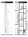
1
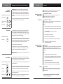
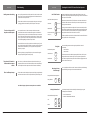
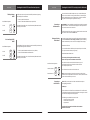
Broadcasting the best results.
If you haven’t used Pure Digital
Fiberlink® lately, you should
review our comprehensive line
of fiber based solutions today.
User’s Manual
Designed exclusively for the
A/V Professional, each
Pure Digital Fiberlink® is
designed and built with
decades of Pro A/V experience.
Convert your high-resolution DVI
Call your Sales Representative
or visit us online at
commspecial.com
computer sources into a SMPTE standard
HD or SD SDI signal for broadcasting
on air or integrating into a professional
Blue
video production system.
Blue
Scan Do® HD does not require that you
White
install any special software or hardware
White
on your computer.
Black
World Headquarters
DVI Computer Video to HD/SD-SDI Scan Converter
with Genlock Input and Fiber Optic Output
55 Cabot Court
Hauppauge, New York 11788 USA
Tel: (631) 273-0404
Fax: (631) 273-1638
[email protected]
Asia
Class 1 Laser Product
Communications Specialties Pte Ltd
100 Beach Road
#22-09 Shaw Tower
Singapore 189702
Tel: +65 6391 8790
Fax: +65 6396 0138
[email protected]
commspecial.com | scandohd.tv
©2007 Communications Specialties, Inc. All Rights Reserved.
Black
DVI Computer Video to HD/SD-SDI Scan Converter
with Genlock Input and Fiber Optic Output
Get updates at scandohd.tv
Single Color (B
World Headquarters
55 Cabot Court
Hauppauge, New York 11788 USA
Tel: (631) 273-0404
Fax: (631) 273-1638
[email protected]
Asia
CSI and the triangle designs are trademarks of
Communications Specialties, Inc.
Communications Specialties Pte Ltd
100 Beach Road
#22-09 Shaw Tower
Singapore 189702
Tel: +65 6391 8790
Fax: +65 6396 0138
[email protected]
P/N 126128 Rev. E
October 18, 2007
commspecial.com
Scan Do is a registered trademark of
Communications Specialties, Inc.
Pure Digital Fiberlink and the starburst logo is a registered
trademark of Communications Specialties, Inc.
Single Color (B
on Black Backg
Blue
Scan Do® HD
Contents
Black
What’s included with your new Scan Do® HD. . . . . . . . . . . . . . . . . . . . . . 3
Introduction. . . . . . . . . . . . . . . . . . . . . . . . . . . . . . . . . . . . . . . . . . . . . . . . . . . . 4
Installation . . . . . . . . . . . . . . . . . . . . . . . . . . . . . . . . . . . . . . . . . . . . . . . . . . . . . 5
Installation Steps. . . . . . . . . . . . . . . . . . . . . . . . . . . . . . . . . . . . . . . . . . . . . . . . 5
Available Outputs. . . . . . . . . . . . . . . . . . . . . . . . . . . . . . . . . . . . . . . . . . . . . . . 5
Supported DVI Input Types . . . . . . . . . . . . . . . . . . . . . . . . . . . . . . . . . . . . . . 5
Video Standard Selection. . . . . . . . . . . . . . . . . . . . . . . . . . . . . . . . . . . . . . . . 5
Operation. . . . . . . . . . . . . . . . . . . . . . . . . . . . . . . . . . . . . . . . . . . . . . . . . . . . . . . 6
General Front Panel Operation:
Moving the Image. . . . . . . . . . . . . . . . . . . . . . . . . . . . . . . . . . . . . . . . . . . . . 7
Sizing the Image . . . . . . . . . . . . . . . . . . . . . . . . . . . . . . . . . . . . . . . . . . . . . . 7
Changing the Image Appearance. . . . . . . . . . . . . . . . . . . . . . . . . . . . . . 8
Genlock Mode . . . . . . . . . . . . . . . . . . . . . . . . . . . . . . . . . . . . . . . . . . . . . . . . 8
Genlock Phasing . . . . . . . . . . . . . . . . . . . . . . . . . . . . . . . . . . . . . . . . . . . . . . 8
Anti-Flicker Function. . . . . . . . . . . . . . . . . . . . . . . . . . . . . . . . . . . . . . . . . . 9
Test Signals . . . . . . . . . . . . . . . . . . . . . . . . . . . . . . . . . . . . . . . . . . . . . . . . . . . 9
Returning to Factory Default Settings. . . . . . . . . . . . . . . . . . . . . . . . . . 9
Locking the Front Panel . . . . . . . . . . . . . . . . . . . . . . . . . . . . . . . . . . . . . . . 9
Fiber Optic Output On/Off. . . . . . . . . . . . . . . . . . . . . . . . . . . . . . . . . . . 10
On Screen Display (OSD) On/Off. . . . . . . . . . . . . . . . . . . . . . . . . . . . . 10
Viewing the IP Address. . . . . . . . . . . . . . . . . . . . . . . . . . . . . . . . . . . . . . . 11
Connecting to the RS-232 Port. . . . . . . . . . . . . . . . . . . . . . . . . . . . . . . . 11
Troubleshooting . . . . . . . . . . . . . . . . . . . . . . . . . . . . . . . . . . . . . . . . . . . . . . . 12
Accessories . . . . . . . . . . . . . . . . . . . . . . . . . . . . . . . . . . . . . . . . . . . . . . . . . . . . 13
Statement of Warranty . . . . . . . . . . . . . . . . . . . . . . . . . . . . . . . . . . . . . . . . . 14
Certification Information. . . . . . . . . . . . . . . . . . . . . . . . . . . . . . . . . . . . . . . 15
Specifications. . . . . . . . . . . . . . . . . . . . . . . . . . . . . . . . . . . . . . . . . . . . . . . . . . 16
About Your Scan Do® HD and Notes. . . . . . . . . . . . . . . . . . . . . . . . . . . . . . 17
Scan Do® HD Functions at a Glance . . . . . . . . . . . . . . . . . . . . . . . . . . . . . . 19
Scan Do® HD User’s Manual
PROC CONTROL Button Operation
Change Line Count
LINE
COUNT
Choose Parameter
Change Vertical Rate
VERT
RATE
Increase or Decrease
Setting
Reset Setting:
+
Change Rate Division
RATE
DIV
Toggle Interlaced or
Progressive
I/P
Turn On/Off
PAN
Move Left or Right
Upper right corner
Lower right corner
Choose Parameter
DLY
Reset Offset to Zero
+
+
+
+
Decrease Zoom
1:1 Ratio, when in
H Only or V Only modes:
Scan Do® HD User’s Manual
+
ADV
Anti-Flicker Button Operation
GENLOCK +
Turn Off
GENLOCK +
+
+
Turn On
GENLOCK
+
Phasing
Turn Off
GENLOCK
+
Phasing
GENLOCK +
GENLOCK +
Manual Mode
ANTI
Until Led is on
FLICKER
Change Value Increase Anti-Flicker Level ( 1- 8 )
ANTI
While Led is on
FLICKER
Move Cursor
100% Color Bars
TEST
75% Color Bars
TEST
1x
2x
View the IP Address
Enter Edit Mode
IP Address Button Operation
ANTI
Until Led is off
FLICKER
+
PROC
+ CONTROL
Turn On
Auto Mode
Test Button Operation
Increase Zoom
Full Screen,
both H & V:
DLY
Zoom
Full Screen,
maintain aspect ratio:
ADV
+
Zoom Button Operation
Choose Parameter
ZOOM
On Screen Display ( OSD )
On/Off Button Operation
GENLOCK
Phasing
Set Advance
Lower left corner
Unlock
PAN
Genlock Phasing Button Operation
+
Upper left corner
ZOOM +
GENLOCK
Set Delay
Center horizontally
Lock
Fiber Optic On/Off Button Operation
or
or
Center vertically
or
Front Panel
Lock/Unlock Button Operation
Until Led is on
Move Up or Down
PROC
CONTROL
Genlock Button Operation
PAN Button Operation
Controlling the Scan Do® HD Remotely:
Connecting to the Ethernet Port. . . . . . . . . . . . . . . . . . . . . . . . . . . . . . 11
Page 2
Output Format Button Operation
Enter Pan Mode
Setting the Output Format . . . . . . . . . . . . . . . . . . . . . . . . . . . . . . . . . . . . 6
Front Panel Quick Reference Chart
White
or
or
Save Changes
GENLOCK +
Cancel Changes
GENLOCK
+
Phasing
Reset Ethernet Port
GENLOCK
+
Phasing
Factory Defaults Button Operation
Factory Defaults
TEST +
ANTI
FLICKER
Singl
(631) 273-0404 | commspecial.com
Check for Scan Do® Updates at:
scandohd.tv
Page 19
Singl
on Bl
Scan Do® HD
Notes
Scan Do® HD
What’s Included with your Scan Do® HD
1 - Scan Do® HD DVI Computer Video to HD/SD-SDI Scan Converter
1 - AC power line cord
1 - DVI Computer input cable
1 - CAT5 Ethernet cable
1 - RS-232 serial cable
1 - User’s Manual ( This document )
1 - Remote Control Manual
1 - Scan Do HD Front Panel Quick Reference Chart
1 - Rack Mounting Kit
1 - Accessory Pack ( Replacement fuse, rubber feet )
Available Optional Accessories:
• AC line cords for North America, Japan, UK, Europe or Australia
• Fiber Optic to Electrical Receiver for HD/SD-SDI optical output
• Expand Scan Do HD’s input capabilities: CSI’s Model 2100 performs
broadcast quality VGA or Component Video to DVI conversion.
• Fiber Optic and Coaxial Cables
For more about available accessories for your Scan Do® HD,
please see page 13.
Page 18
Scan Do® HD User’s Manual
Scan Do® HD User’s Manual
Page 3
Scan Do® HD
Introduction
Scan Do® HD
Thank you for purchasing Scan Do® HD, the high-performance DVI
computer video to HD/SD-SDI scan converter.
With Scan Do® HD, you now have the ability to convert your high-resolution
DVI computer video sources into a SMPTE standard HD or SD SDI signal for
broadcasting on air or integrating into a professional video production system.
Scan Do® HD does not require that you install any special software or hardware on
your computer.
Like all the products from Communications Specialties, Scan Do® HD comes with
our continuing commitment to provide support. Should you need to contact us
for support, our office is open Monday through Friday, from 8:30 AM to 5:00 PM
Eastern Time. Our Singapore office is open Monday through Friday, from 9:00 AM
to 5:00 PM Singapore time.
We also offer a comprehensive web site for your added convenience.
Visit us at scandohd.tv
About Your Scan Do® HD
Serial Number:
Date of Purchase:
Purchased From:
Installed By:
Installation Location:
Configuration:
To avoid fire and/or personal injury,
please observe these safety
and operating precautions:
Use the Proper Power Cord. Use only the proper power cord specified for this
product and certified for the country of use.
Ground the Product. This product is grounded through the grounding
conductor of the power cord. To avoid electric shock, the grounding conductor
must be connected to the earth ground. Before making connections to the input
and output of the product, make sure that the product is properly grounded.
Prevent Electrical Circuit Overloading. The unit operates from a single-phase
power source with the neutral conductor at or near earth ground. The line
conductor is fused for over-current protection. A protective ground connection
through the grounding conductor in the power cord is essential for safe
operation. Ensure that the available AC line power is sufficient to meet the power
requirements of the unit without exceeding the rated load for the supply circuit
and its wiring.
Observe These Rack Mount Installation Precautions. If the product is to be
rack mounted, make sure the following are observed:
* The unit operates correctly in ambient temperatures from 0 degrees C to +50 degrees C. Leave space for cooling by ensuring standard side clearance for
rack mounting or 2 inches of side clearance for table top use. Also, ensure rear
clearance of approximately 3 inches so that cables are not damaged by sharp
bends.
* Reduced air flow through and around the unit may have an adverse effect on
the operation and safety of the unit. Make sure that air flow is adequate to
ensure the ambient temperature does not rise above or below the specified
levels. When rack mounted, no equipment or other item is to be placed directly on top of the unit as this will make the mounting of the unit unsafe and unstable.
Page 4
Scan Do® HD User’s Manual
Scan Do® HD User’s Manual
Page 17
Specifications
Scan Do® HD
Input Resolutions
Input/Output
Output Resolutions
Scan Do® HD
Follow these steps for
a simple and successful
Scan Do® HD Installation
• DVI-D single link resolutions
• RGB, Progressive or Interlaced, up to 1920 x 1200 @ 60 Hz
• Pixel clock frequency 25 to 165 MHz
Genlock
Processing Controls
Image Size & Positioning
Control Interfaces
Additional Features
Dimensions
Power
Page 16
Step 1:
Power Off both your computer and the Scan Do HD and disconnect
your DVI monitor from the DVI monitor port on your computer.
Step 2:
Using the supplied DVI input cable provided with the Scan Do HD,
connect one end to the DVI monitor port on your computer and the
other to the connector on the rear panel of the Scan Do HD marked DVI-D Input.
Step 3:
Connect your DVI monitor, if you have one, to the Scan Do HD
connector labeled DVI-D Loop Through. Use the cable that is attached
to your monitor for this purpose.
Step 4:
Connect the AC line cord provided with the Scan Do HD to the AC
power connector. Plug the AC line cord to the wall outlet to provide
power.
Step 5:
Connect the Scan Do HD’s HD/SD-SDI output to your video equipment.
If desired, you may use all outputs simultaneously. (Refer to the next
section.)
Step 6:
Turn On the Scan Do HD first. Then, turn On the DVI monitor. Finally,
turn On your computer. The green input LED’s on the front panel
labeled Locked and Valid should illuminate, indicating the unit is
receiving a valid signal from the computer.
• Input: DVI-D, or DVI-I (digital signal only) single link with active loop-through
• Coaxial SDI output x 2; per SMPTE 292 & 259
• Optical SDI output x 1; per SMPTE 292 & 297
(1310 nm, single mode or multimode, SC/PC, -8.0 dBm nominal output power)
10-bit HD-SDI per SMPTE 292:
• 720/60/P
• 720/59.94/P
• 720/29.97/P
• 720/25/P
• 1035/60/I
• 1035/59.94/I
• 1080/50/I
• 1080/30/P
• 1080/24/P
• 1080/23.98/P
• 720/50/P
• 720/24/P
• 1080/60/I
• 1080/29.97/P
• 720/30/P
• 720/23.98/P
• 1080/59.94/I
• 1080/25/P
10-bit SD-SDI per SMPTE 259:
• 525/59.94/I (NTSC) • 625/50/I (PAL)
Video Processing
Installation Instructions
• 10-bit, all digital
• NTSC/PAL black burst or HD tri-level sync
• HD resolutions will genlock to NTSC/PAL black burst at the same vertical rate
• Passive loop-through
• H, V and Clock phasing with a range of one output vertical period
and resolution of 840 pS
Available Outputs
• Brightness
• Contrast
• Hue
• Color Saturation
• Sharpness
HD/SD-SDI (2): These outputs generate a SMPTE 292M or 259M compatible serial
digital signal. These outputs simultaneously produce the same signal and are
not capable of producing two different resolutions. The signal produced at these
outputs is determined by the settings for Line Count, Vert Rate, I/P, and Rate Div.
Note: If one of the HD/SD-SDI Outputs is not used, it should be terminated at the
connector in 75 ohms to improve the eye pattern of the output that is used.
Fiber Optic: This output is an optical version of the copper HD/SD-SDI outputs.
This optical output is in accordance with SMPTE 292M or 297M and uses an SC
optical connector. This output will support either single mode or multimode
(62.5u or 50u) fiber types. The factory default is off.
• Separate H & V positioning
• Zoom and Shrink; H & V separate or together
• 10/100 Base-T ethernet LAN port with internal HTML host
• RS-232 port
• Front panel push button
DVI Input Types Supported
• Variable flicker reduction
• Test pattern generator: color bars at 100% and 75% Saturation
• Multiple pre-set storage and recall settings through remote control interfaces
• On Screen Display (OSD)
• Factory defaults reset
• Rack mount kit included
• RoHS compliant
• 16.75 W (without rackmount ears) x 1.75 H x 10 D (inches)
• 425 W x 44 H x 254 D (mm)
• Weight: 5.5 pounds; 2.49 kg
Scan Do® HD will only support DVI single-link digital video signals. If a DVI-I source
is used, only the single-link digital signals will be processed.
Video Standard Selection
The output video standard and timing is established by a combination of settings
of the Line Count, Vert Rate, I/P, and Rate Div front panel settings.
The Scan Do HD will only allow valid SMPTE standards to be chosen. Please refer
to the section “Setting the Output Format” for instructions on selecting the video
standard from the front panel.
• Internal universal input AC power supply
• 95 - 250 volts AC, 47 - 63 Hz, 20 watts
Scan Do® HD User’s Manual
DVI-D Loop Through: This output is for a connection to a local DVI monitor.
It will show what is present on the DVI input. If the Scan Do HD is powered on, the
EDID information from the monitor connected to this output will be passed to the
computer's DVI port when the computer is booted. If no monitor is connected to
this output, then the Scan Do HD will provide EDID information to the computer.
Scan Do® HD User’s Manual
Page 5
Scan Do® HD
Setting the Output Format
Output Format Button Operation
Change Line Count
LINE
COUNT
Change Vertical Rate
VERT
RATE
Change Rate Division
RATE
DIV
Toggle Interlaced or
Progressive
I/P
Special Operation Notes:
For NTSC or PAL output formats, you
need only select 483 or 576 using the
LINE COUNT button. All other selections
are implied when either of these Line
Count selections are made.
If, at any time, the Scan Do HD detects
that no more valid selections can be
made, no additional LEDs will illuminate
and it will set your selections as the
Output Format after a 2-3 second delay.
After pressing LINE COUNT, you can
choose to configure Vertical Rate, Rate
Division and I/P in any order.
If you accidentally enter Output Format
mode, please wait 4-6 seconds and the
Scan Do HD will not change the Output
Format and will exit Output Format
mode.
Page 6
Operating the Scan Do® HD - General Front Panel Operation
The desired output format is established through a combination of four front
panel buttons:
Scan Do® HD
FCC Statement
WARNING:
This equipment generates, uses and can radiate radio frequency energy and if
not installed and used in accordance with the instruction manual, may cause
interference to radio communications. It has been tested and found to comply
with the limits for a Class A computing device pursuant to Subpart B of Part 15
of FCC Rules, which are designed to provide reasonable protection against such
interference when operated in a commercial environment. Operation of this
equipment in a residential area is likely to cause interference in which case the
user, at his own expense, will be required to take whatever measures may be
required to correct the interference.
CE Information
Standards to which conformity is declared:
EMC
EN 55022: 1994, CISPR 22: 1993, Class A Limit
EN 50082-1: 1992
IEC 801-2: 1991
IEC 801-3: 1984
IEC 801-4: 1988
Line Count ( LINE COUNT button ):
Determines the number of active horizontal lines in the image.
Vertical Rate ( VERT RATE button ):
Determines the base vertical refresh rate of the output. This is the number of
frames per second if the output is progressive and the number of fields per
second if the output is interlaced.
Rate Division ( RATE DIV button ):
Determines if the base Vert Rate is to be divided by 1.001 or not. For example, to
set the output vertical field rate to 59.94 the user would set the Vert Rate to "60",
the Rate Div to "1/1.001".
Interlaced/Progressive ( I/P Button ):
Determines if the output format is to be Interlaced or Progressive. Not all
options are available for all Line Counts and Vert Rates.
Note: The allowed output format combinations of the above are specified in the
Specifications section of this manual.
FDA & IEC Statement
To set a specific output format:
Step 1:
Press the LINE COUNT button. All the LEDs will blink slowly.
Continue to press the Line Count button until you have selected
the value you want and wait 2-3 seconds. Any additional options
will then illuminate.
Step 2: After making your Line Count selection, the valid Vertical Rates,
Rate Divisions and I/P will illuminate and the default selections will
blink. Invalid selections will not illuminate.
If the default options are desired, no further action is required.
If you wish to change the Vertical Rate, press the VERT RATE button
to select the value you want and wait 2-3 seconds.
Step 3:
After making your Vertical Rate selection, the valid Rate Division and I/P settings will illuminate and the default selections will
blink. Invalid selections will not illuminate.
If the default options are desired, no further action is required.
If you wish to change the Rate Division, press the RATE DIVISION
button to select the value you want and wait 2-3 seconds.
Step 4:
After making your Rate Division selection, the valid I/P settings
will illuminate and the default selection will blink.
Invalid selections will not illuminate.
If the default options are desired, no further action is required.
If you wish to change the I/P, press the I/P button
to select the value you want and wait 2-3 seconds.
The Output Format will now be set and your selected options
will be illuminated.
Scan Do® HD User’s Manual
Certification
Turn off unit or laser before connecting
or disconnecting optical cable!
Complies with FDA performance standard for laser products, Title 21,
Code of Federal Regulations, Sub-Chapter J and IEC 60825-1
The fiber optic transmitting element in the Scan Do® HD contains a solid state Laser Diode
located within the optical connector. This device emits invisible infrared electromagnetic
radiation which can be harmful to human eyes. The radiation from this optical connector,
if viewed at close range without a fiber optic cable connected to the optical connector,
may be of sufficient intensity to cause instantaneous damage to the retina of the eye.
Direct viewing of this radiation should be avoided at all times.
WARNING
TO REDUCE THE RISK OF FIRE OR ELECTRONIC SHOCK, DO
NOT EXPOSE THIS APPLIANCE TO RAIN OR MOISTURE.
CAUTION
RISK OF ELECTRIC SHOCK. DO NOT OPEN!
CAUTION
TO REDUCE THE RISK OF ELECTRONIC SHOCK, DO NOT REMOVE
COVER. NO USER SERVICEABLE PARTS INSIDE. REFER SERVICING
TO QUALIFIED SERVICE PERSONNEL.
This symbol warns the user of uninsulated
voltage within the unit that can cause
dangerous electronic shocks.
Scan Do® HD User’s Manual
This symbol alerts the user that there are
important operating and maintenance
instructions in the literature accompanying
this unit.
In the literature accompanying this unit,
this symbol warns the user of dangerous
conditions to avoid.
Page 15
Scan Do® HD
Warranty
Operating the Scan Do® HD - General Front Panel Operation
Scan Do® HD
Communications Specialties, Inc. (CSI) warrants that, for a period
of three years after purchase by the Buyer, Scan Do® HD will be free from defects
in material and workmanship under normal use and service. A Return Material
Authorization (RMA) number must be obtained from CSI before any equipment
is returned by the Buyer. All materials must be shipped to CSI at the expense and
risk of the Buyer.
Moving the Image
PAN Button Operation
Pressing certain combinations of arrow buttons simultaneously will perform
specific functions when in the Pan mode:
CSI’s obligation under this warranty will be limited, at its option, to either the
repair or replacement of defective units, including free materials and labor. In no
event shall CSI be responsible for any incidental or consequential damages or loss
of profits or goodwill.
Enter Pan Mode
CSI shall not be obligated to replace or repair equipment that has been damaged
by fire, war, acts of God, or similar causes, or equipment that has been serviced by
unauthorized personnel, altered, improperly installed, or abused.
Move Up or Down
or
Center vertically
+
RMA numbers and repairs can be obtained from:
Communications Specialties, Inc.
55 Cabot Court
Hauppauge, NY 11788 USA
Tel: (631) 273-0404
Fax: (631) 273-1638
Upper left corner
Lower left corner
* UP and DOWN arrows: Centers the image vertically
or
+
+
+
Upper right corner
Communications Specialties Pte Ltd
100 Beach Road
#22-09 Shaw Tower
Singapore 189702
Tel: +65 6391 8790
Fax: +65 6396 0138
Until Led is on
Center horizontally
or, in the Asia Pacific Region:
PAN
Move Left or Right
Lower right corner
+
+
Sizing the Image
RMA numbers can also be obtained from our web site: commspecial.com
Zoom Button Operation
Please have your serial number (located underneath Scan Do HD) available.
Choose Parameter
Increase Zoom
1:1 Ratio, when in
H Only or V Only modes:
Page 14
Scan Do® HD User’s Manual
Scan Do® HD User’s Manual
* LEFT and UP arrows: Places the top left corner of the input image in the top left
corner of the output
* LEFT and DOWN arrows: Places the bottom left corner of the input image in the
bottom left corner of the output
* RIGHT and UP arrows: Places the top right corner of the input image in the top
right corner of the output
* RIGHT and DOWN arrows: Places the bottom right corner of the input image in
the bottom right corner of the output
ZOOM: This button will size the image either by increasing or decreasing the
visible size in the raster. The UP and DOWN arrows are used to increase and
decrease respectively the size of the image. Press and hold for a series of fine
steps followed by a more coarse adjustment.
Pressing certain combinations of arrow buttons simultaneously will perform
specific functions when in the Zoom mode:
Decrease Zoom
Full Screen,
both H & V:
* LEFT and RIGHT arrows: Centers the image horizontally
When in H&V mode, both the Horizontal and Vertical outputs will be affected.
When in H Only mode, only the Horizontal output will be affected.
When in V Only mode, only the Vertical output will be affected.
Zoom
Full Screen,
maintain aspect ratio:
PAN: Press PAN to enter Pan Mode. The LED to the right of the button will light to
indicate the function is active. Use the LEFT, right, up or down arrow keys to
position your image. Press and hold for a series of fine steps followed by a more
coarse adjustment.
+
+
+
* UP and DOWN arrows: Zooms the image in one direction while keeping the
input aspect ratio the same by proportionately zooming the opposite
direction.
*
When in H Only or V Only mode, the UP and DOWN arrows provide
a 1:1 input/output ratio.
LEFT and Right arrows: Zooms the image to full screen both horizontally and vertically when in H&V mode, horizontally when in H Only mode,
and vertically when in V Only mode.
Page 7
Operating the Scan Do® HD - General Front Panel Operation
Scan Do® HD
Changing the
Image Appearance
PROC CONTROL Button Operation
Choose Parameter
PROC
CONTROL
PROC CONTROL: This function alters the displayed image's appearance by
varying the Brightness, Contrast, Hue, Saturation and Sharpness. The PROC
CONTROL button is pressed to sequence through the different image process
functions. Once the desired function is selected, use the UP and DOWN arrows
to increase or decrease respectively the degree of augmentation to that image
parameter.
Pressing the UP and DOWN arrows simultaneously, while in the PROC CONTROL
mode, will return the active function to its default state.
Increase or Decrease
Setting
or
Reset Setting:
+
Accessories
Scan Do® HD
The following accessories are available for Scan Do® HD. They may be ordered
from your dealer or directly from Communications Specialties, Inc.
Convert Scan Do’s Optical
Output to Copper
DVI over Fiber
Pure Digital Fiberlink® 3151 Series
The 3151 Series is the ideal solution for broadcast professionals that need to
bridge their fiber backbone with a copper backbone.
Get more information online at commspecial.com\
Pure Digital Fiberlink® 7500 Series
DVI transmission (up to 1920x1200) and stereo audio over one single mode fiber
without compression, scaling or adjustments.
Features:
• Transmits single-link DVI (640 x 480 up to 1920 x 1200 - 165 MHz pixel clock)
Genlock Mode
Genlock Button Operation
Turn On/Off
The Genlock button turns the genlock mode On and Off. When the genlock
mode is on, the unit looks at the genlock input and determines if a signal is
present. During this time the Searching LED will be lit. If a signal is present, the
unit determines if its format is compatible with the output format selected. If the
genlock input is valid, the Locked LED will illuminate.
• Uses no compression, color space conversion or scaling
for crystal clear signals
The Scan Do HD will accept either NTSC/PAL composite video or HD tri-level sync.
The genlock vertical rate must match the output vertical rate in order to achieve
genlock but the horizontal rates do not have to match. Therefore, it is possible to
lock to an NTSC signal and produce a 1080i/59.94 output, for example.
GENLOCK
The factory default setting is genlock mode off.
To genlock the Scan Do HD, connect a genlock signal to the Genlock Input
connector on the rear panel. There is a passive loop through from the genlock
input which is accessible on the Genlock Loop Through connector.
Genlock Phasing Button Operation
Choose Parameter
Set Delay
Set Advance
Reset Offset to Zero
Page 8
GENLOCK
Phasing
Expanding Scan Do® HD’s
Input Capabilities
ADV
DLY
+
ADV
• Supports up to 50 feet (15m) DVI input cable
• Requires no adjustments, equalization or de-skewing during installation
CSI’s Model 2100
CSI’s Model 2100 VGA or Component Video to HDMI/DVI Converter was designed
specifically to expand the Scan Do® HD’s input capabilities. The 2100 uses no
scaling, which could add unwanted artifacts, making it ideal to use in a broadcast
environment.
Press the GENLOCK PHASING button to sequence through the three LEDs to select
the parameter to phase.
•Compliant with HDMI specification 1.0
•Supports up to 1600x1200 @ 60 Hz VGA input or up to 1080p input
with stereo audio to HDMI (with audio) or single-link DVI (without audio).
Cabling
Fiber Optic Cable
We can provide you with optic cable of varying types and lengths. Fiber optic
cabling is available in PVC, Plenum and Armor Jacketed. Please contact a Sales
Representative today.
Please visit commspecial.com for the latest products, specifications
and other breakthrough products.
NOTE: Clock Phasing movement is in 840 picosecond (pS) increments and may
not be visible on some TV waveform monitors and rasterizers.
Scan Do® HD User’s Manual
•Connects computers with analog RGBHV (VGA) video output or DVD players
with component output to HD ready Plasma, LCD, DLP TV, or Scan Do® HD
The Genlock Phasing button, along with the DLY and ADV arrow buttons will
allow for phasing the output of the Scan Do HD relative to the genlock reference.
Horizontal, Vertical and Pixel Clock phasing can be adjusted.
NOTE: For NTSC and PAL output formats, set the Vertical Phasing to Zero Offset
before adjusting any phasing.
• Only one fiber used - no pixel skewing
Features:
•No scaling is performed resulting in crystal clear output.
When the desired genlock phasing mode is enabled, the Left/DLY and Right/ADV
arrow buttons become the phasing delay and advance functions. Pressing the DLY
and ADV buttons simultaneously will reset the phasing mode to zero offset.
DLY
• Advanced input circuit equalizes and re-clocks noisy
and distorted DVI input signals
NOTE: If the Genlock Loop Through is not used, it should be terminated at the
connector in 75 ohms.
Genlock Phasing
• Supports HDTV resolutions of 480p, 720p, 1080i and 1080p (DVI format only)
Scan Do® HD User’s Manual
Page 13
Scan Do® HD
Nothing seems to be working
Troubleshooting
• Are any of the green LEDs lit on the front panel? If not, check to make sure that
the AC power cord is connected and plugged into the AC wall outlet and the
power switch on the rear panel is On.
• Check to make sure that the computer is properly sending out a DVI-D signal
by plugging the DVI monitor directly into the computer’s video output.
There is no video on the DVI
Loop-thru or the SDI outputs
The color on the TV monitor is
different than the computer
monitor
Operating the Scan Do® HD - General Front Panel Operation
Scan Do® HD
• It is important for most PC's with a DVI output to have the DVI monitor
connected at the time the PC is booted. When using the Scan Do HD with a
PC having a DVI output, make sure the Scan Do HD's DVI input is connected to
the PC's DVI output and the Scan Do HD is On before the PC is booted. Failure
to do so may cause the PC to fail to recognize a DVI monitor is connected and
shut off all DVI signalling from the DVI output of the PC.
Anti-Flicker Function
Anti-Flicker Button Operation
Auto Mode
ANTI
Until Led is off
FLICKER
Manual Mode
ANTI
Until Led is on
FLICKER
Increase Anti-Flicker Level ( 1- 8 )
ANTI
While Led is on
FLICKER
• Press the Test button to see if you get color bars on the SDI outputs. If you do
get color bars, then the problem is related to your input signal. Check the items
mentioned in the above bullet. If you do not get color bars, the problem is
related to your output.
Test Button Operation
• When using a laptop, try turning off the laptop’s LCD screen and having the
DVI signal output through the external port only.
100% Color Bars
TEST
75% Color Bars
TEST
1x
2x
• The colors on your SDI monitor will never exactly match the colors on your
computer monitor because each of these devices reproduce color differently.
It is also likely that the color temperature of each monitor is set differently.
• Check to make sure that Fiber Optic Output is turned On by pressing GENLOCK
and the UP arrow buttons on the front panel. The factory default setting is off.
Pressing the ANTI-FLICKER button will put the function in manual mode and the
LED will be lit. Sequential pressing of the button will increase the anti-flicker level
from 1 (least reduction) to 8 (most reduction). Pressing it again after level 8 will
extinguish the LED and return the function to auto mode.
Scan Do HD will generate several test signals in place of the converted
video output:
• 100% Color bars
• 75% Color bars
These test patterns can be enabled by pressing the TEST button. The first press
will generate the 100% Color bars signal. The second press will generate the
75% color bar signal and the next press will shut off the test signal generator and
return to the converted output.
Returning to Factory
Default Settings
There is no fiber optic output
When the ANTI-FLICKER LED is off, the function is in automatic mode where the
best level of flicker reduction is selected for you based on the input and output
timing parameters detected.
If OSD is enabled, the mode and value of the Anti-Flicker function will be shown in
the upper left corner of the output display.
Test Signals
The ANTI-FLICKER button will step through 8 levels of flicker reduction. This
function is used primarily for interlaced output settings to reduce vertical flicker at
the expense of vertical detail.
You may quickly return all Scan Do® HD functions to their factory default settings
by simultaneously pressing the TEST and ANTI-FLICKER buttons.
Factory Defaults Button Operation
Factory Defaults
TEST +
ANTI
FLICKER
For additional support, please visit commspecial.com or scandohd.tv
Locking the Button Panel
* To Lock: ZOOM and PAN
* To Unlock: ZOOM and PROC CONTROL
Lock/Unlock Button Operation
Page 12
Scan Do® HD User’s Manual
Lock
ZOOM +
Unlock
ZOOM
Scan Do® HD User’s Manual
The front panel may be locked or unlocked by simultaneously pressing the
following button combinations:
PAN
PROC
+ CONTROL
Page 9
Operating the Scan Do® HD - General Front Panel Operation
Scan Do® HD
Fiber Optic Output
On/Off
Scan Do HD can be controlled remotely in two ways. A standard Ethernet port
can be used to control the unit using a standard browser (i.e. Internet Explorer,
Firefox) enabled with Java version 1.6 (JRE 6) or later. It can also be controlled
using ASCII command strings through the RS-232 serial port.
The fiber optic output may be turned On and Off by simultaneously pressing
the following button combinations:
On/Off Button Operation
* To turn On: GENLOCK and UP arrow
* To turn Off : GENLOCK and DOWN arrow (Factory Default)
Turn On
GENLOCK +
The Genlock Phasing LEDs H, CLK, and V, will momentarily illuminate when the
above key presses are made.
Turn Off
GENLOCK +
Operating the Scan Do® HD - Controlling the Scan Do® HD Remotely
Scan Do® HD
Connecting to
the Ethernet Port
The default setting for the unit is to accept an IP address from the router to which
it is connected. This is referred to as DHCP mode.
Viewing and Setting
the IP Address
On Screen Display (OSD)
On/Off
Turn On
GENLOCK
+
Phasing
Turn Off
GENLOCK
+
Phasing
To see the IP settings the unit has acquired from the router after the connection
is made, ensure that the On Screen Display is enabled and press the following
buttons simultaneously for an 30 second on-screen display of the IP settings:
GENLOCK and LEFT arrow
The OSD feature of the Scan Do HD may be turned On and Off by simultaneously
pressing the following button combinations:
On/Off Button Operation
10/100 BASE-T: The rear panel Ethernet port will accept a standard 10/100 Base-T
Ethernet connection. The unit will automatically adjust to either speed from the
hub, switch or router that it is connected to.
If you connect the ethernet cable after you have powered on your Scan Do HD,
you may have reset the ethernet port by pressing:
* To turn On: GENLOCK PHASING and UP arrow (Factory Default)
* To turn Off: GENLOCK PHASING and DOWN arrow
GENLOCK PHASING and RIGHT arrow
The Genlock Phasing LEDs H, CLK, and V, will momentarily illuminate when the
above key presses are made.
The unit may also be assigned an IP address manually.
Please refer to your Scan Do® HD Remote Control manual.
IP Address Button Operation
View the IP Address
GENLOCK +
Reset Ethernet Port
GENLOCK
+
Phasing
Connecting to
the RS-232 Port
Once the Scan Do HD is connected, launch the browser on your PC.
In the Address bar of the browser enter the IP address of the unit.
For example: http://192.168.1.54
You will now see the control screen of the Scan Do HD.
Note: It is important that your browser have Java version 1.6 (JRE 6) or later
installed. This is normally standard on most browsers. However, the latest version
of Java can be downloaded at: java.sun.com
RS-232: This port is designed to work with a standard RS-232 serial port.
The signalling parameters are:
19200, 8, N, 1
There is no hardware or software flow control and Generic TTY should be used. A
"straight-through" DB-9 M/F cable should be used when connecting to a standard
PC. Scan Do® HD is designed to be DCE equipment.
The following pins on the DB-9F connector are used:
2 - Data Transmit from Scan Do HD
3 - Data Receive into Scan Do HD
5 - Signal Ground
A complete list of commands can be found in the Scan Do® HD
Remote Control manual.
Page 10
Scan Do® HD User’s Manual
Scan Do® HD User’s Manual
Page 11