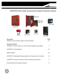
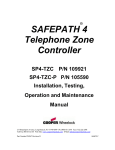
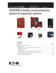
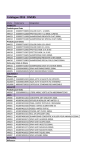
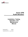
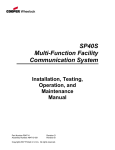
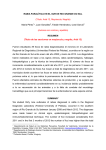
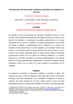
1
273 Branchport Avenue
Long Branch, N.J. 07740
(800) 631-2148
www.wheelockinc.com
Thank you for using our products.
INSTALLATION INSTRUCTIONS
ADDRESSABLE PAGING SPLITTER
(FOR SP40/2, SPB-160, SPB-80/4, and SPB-320)
Use this product according to this instruction manual. Please keep this instruction manual for future reference.
MODEL NUMBER:
109920 SP4-APS
1.0 GENERAL:
The Addressable Paging Splitter module (SP4-APS) is designed to be used with Wheelock’s SP40/2 SAFEPATH4 panel and
the SP4-TZC Zone Controller. The SP4-APS can also be mounted in SAFEPATH4 Audio Booster (SPB-160, SPB-80/4, and
SPB-320) panels. The SP4-APS provides a means for expanding one supervised audio output zone to four Class B or two
Class A supervised zones. The SP4-APS also provides two expansion outputs that can be used to add additional audio
booster modules in Class A or B configuration. The SP4-APS is UL Listed under Standard 864, Control Units for Fire
Protective Signaling Systems. It is for indoor use only.
One SP4-APS can be mounted inside the SP40/2 panel. The use of the Splitter Mounting Bracket (SPMB4Z) is required
when mounting the SP4-APS splitter(s) inside the Audio Booster panels.
The Addressable Paging Splitter module (SP4-APS) is also used to expand and distribute supervised telephone paging and
background music to selected zones when the SAFEPATH4 system is not in the alarm condition. When the SAFEPATH4
system is in the alarm condition all telephone paging and background music inputs are silenced and the emergency message
is broadcast on all zones. The SP4-APS is used with the Telephone Zone Controller (SP4-TZC) and controls the distribution
of the telephone paging and background music functions.
NOTE: Use of the Telephone Zone Controller (SP4-TZC) is supplementary.
The SP4-APS contains 16 LED indicators used to monitor and troubleshoot the module.
Refer to the Installation Instructions for the Telephone Zone Controller (SP4-TZC) P84567 when connecting the SP4-APS
modules for telephone paging and background music operation.
NOTE: All CAUTIONS and WARNINGS are identified by the symbol
letters.
. All warnings are printed in bold capital
WARNING: PLEASE READ THESE INSTRUCTIONS CAREFULLY BEFORE USING THIS PRODUCT.
FAILURE TO COMPLY WITH ANY OF THE FOLLOWING INSTRUCTIONS, CAUTIONS AND WARNINGS
COULD RESULT IN IMPROPER APPLICATION, INSTALLATION AND/OR OPERATION OF THESE
PRODUCTS IN AN EMERGENCY SITUATION, WHICH COULD RESULT IN PROPERTY DAMAGE AND
SERIOUS INJURY OR DEATH TO YOU AND/OR OTHERS.
2.0 SPECIFICATIONS:
The SP4-APS has a maximum power output per zone that cannot exceed what is listed in Table 1.
Table 1: SP4-APS Specifications
Rated
Voltage
24VDC
Rated
Current
0.120A
Audio Input
Voltage
25VRMS
70.7VRMS
Max Power
Per Zone
40W
40W
The total audio power output from all zones on the SP4-APS cannot exceed the audio input power.
Copyright 2005 Wheelock, Inc. All rights reserved.
P84577 G
Sheet 1 of 14
2.1
WIRING SPECIFICATIONS:
Cable Size: All terminal blocks accept #12 - #18 American Wire Gauge (AWG) for single wire connection.
3.0 WIRING INSTRUCTIONS:
NOTE: The terminal blocks on the SP4-APS are removable. To remove a terminal block, pull the block straight up from the
circuit board as shown in Figure 1. Attach wires to the desired connections, then plug the terminal block back on the board
being careful to match and align the pins.
Figure 1: Removable Terminal Block
Figure 2 shows the PC board layout with the locations of all terminal blocks.
TB7
OUT IN TB6 Z1
ALARM
OUT
IN
RS-485
Z2 TB3 Z3
Z4 TB4 EX1
EX2
TB5
SW1
NAC
D38
D34
D39
D40
CC
SP4-APS
D45
24 VDC
OUT IN
POWER
TB1
JP1
D37
D32
D35
D36
B
CLASS
A
SW2
D41
D33
D42
D43
D44
JP1
Shorted = 70Vrms
Open = 25Vrms
AUDIO
TROUBLE
IN
TB2
Figure 2: SP4-APS PC Board
Terminals for the RS-485 connections are used with the SP4-TZC and are explained in the SP4-TZC installation instructions.
3.1 Audio Zone Output Wiring
The SP4-APS can be configured for either “CLASS A” or “CLASS B”. It cannot do both at the same time. The maximum
audio power output on any zone is 40 watts. Expansion (EX1, EX2) terminals follow the Class A or B setting that applies to
all zones.
Instead of speakers, up to four SPB-160 or SPB-80/4 (or two SPB-320) Audio Boosters may be connected to an audio output
zone, provided that nothing else is on that zone. The total number of Audio Boosters combined shall not exceed 33.
NOTE: Factory setting is for Class B Wiring.
3.1.1 “CLASS A” Audio Wiring:
When an installation requires “CLASS A” audio field wiring on the SP4-APS module, the Class Selector Switch (SW2)
must be set for “CLASS A”. Note that no end-of-line resistors (UL Listed 10K Ohm, EOLR) are used on any of
the SP4-APS module audio output zones as shown in Figure 3. Zones Z1 and Z2 are connected in Class A
configuration as well as Z3 and Z4. Figure 3 shows the SP4-APS with SW2 and the audio field wiring set for “CLASS
A”.
The audio zone outputs are either 25Vrms or 70.7Vrms matching the audio input voltage. Remember, the SP40/2 has a
maximum audio output to the splitter of 40 watts, while the Audio Boosters have a maximum audio output to the splitter
of 80 watts.
P84577 G
Sheet 2 of 14
When circuit is not used, jumper
negative to negative and positive
to positive.
TB7
OUT IN TB6 Z1
ALARM
OUT
IN
RS-485
Z2 TB3 Z3
Z4 TB4 EX1
EX2
TB5
SW1
NAC
D38
D34
D39
D40
CC
SP4-APS
D45
D41
D33
D42
D43
D44
JP1
24 VDC
OUT IN
POWER
SW2
D37
D32
D35
D36
B
CLASS
A
TB1
JP1
Shorted = 70Vrms
Open = 25Vrms
AUDIO
TROUBLE
IN
TB2
Figure 3: “CLASS A” Zone Connections
Any unused “CLASS A” zone must be jumpered negative to negative and positive to positive. If the Expansion (EX1,
EX2) terminals are not used, jumpers are required. See Figure 3.
3.1.2 “CLASS B” Audio Wiring:
When an installation requires “CLASS B” audio field wiring, the Addressable Paging Splitter module’s Class Selector
Switch (SW2) must be set for “CLASS B.” Note that end-of-line resistors (UL Listed 10K Ohm, EOLR) are
required at the end of each audio output zone even if no speakers are present on a zone. End-of-line resistors are
required on the EX1 and EX2 connections whether they are used or not. Figure 4 shows the SP4-APS set for CLASS B
audio field wiring:
The audio zone outputs are either 25Vrms or 70.7Vrms matching the audio input voltage. Remember, the SP40/2 has a
maximum audio output to the splitter of 40 watts, while the Audio Boosters have a maximum audio output to the SP4APS of 80 watts.
All circuits are terminated with an
UL Listed 10K Ohm EOLR
EOLR
EOLR
EOLR
EOLR
EOLR
EOLR
TB7
OUT IN TB6 Z1
ALARM
OUT
IN
RS-485
Z2 TB3 Z3
Z4 TB4 EX1
EX2
TB5
SW1
NAC
D38
D34
D39
D40
CC
SP4-APS
D45
24 VDC
OUT IN
POWER
TB1
JP1
D37
D32
D35
D36
B
CLASS
A
SW2
D41
D33
D42
D43
D44
JP1
Shorted = 70Vrms
Open = 25Vrms
AUDIO
TROUBLE
IN
TB2
Figure 4: “CLASS B” Zone Connections
P84577 G
Sheet 3 of 14
3.2 Other Wiring
3.2.1 Expansion Circuit Wiring
The Expansion Circuits (EX1, EX2) are used to link additional audio booster panels (SPB-160, SPB-80/4, and SPB-320)
through the SP4-APS. The audio zone outputs are either 25Vrms or 70.7Vrms matching the audio input voltage. EX1
and EX2 are current limited outputs. If an over current condition is detected, the affected Expansion Zone(s) will
disable their audio output. When the over current condition has been cleared and the affected Expansion Zone(s) go
back to “Normal” condition, the audio output will be re-enabled. To ensure that current limiting works properly, for
25Vrms JP1 must be open, for 70Vrms JP1 must be closed. SPB-160 and SPB-80/4 enclosures contain one audio
booster module, while the SPB-320 contains two. The SP40/2 has a maximum audio output to the splitter of 40 watts,
while the Audio Boosters have a maximum audio output to the splitter of 80 watts. Each audio booster module
connected to the expansion circuits uses 1.2 watts. There is a limit of 33 Audio Boosters that can be connected to an
SP40/2 using SPB-160 or SPB-80/4 models. Each SPB-320 counts as two SPB-160 models.
The wiring of EX1 and EX2 for “CLASS A” or “CLASS B” is determined by the wiring of the zone outputs and switch
SW2 setting. If SW2 is set for “CLASS A”, then all zone outputs and expansion outputs must be wired for “CLASS A”.
When using the SP4-APS in “CLASS B” configuration, end-of-line resistors (UL Listed 10K Ohm, EOLR) must be
used at the end of each expansion circuit.
3.2.2 24VDC Wiring
24 VDC
OUT IN
POWER
JP1
The SP4-APS requires 24VDC input in order to operate. Wire the 24VDC from +/- 24VDC connections on the SP40/2
or the DC OUT connections on the applicable audio booster to the +/- 24VDC IN connections on the splitter. If two
SP4-APS are used on an SPB-160 or two are used with each SPB-160 in the SPB-320 audio booster enclosure, wire the
24VDC OUT connections on the first SP4-APS to the +/- 24VDC IN connection on the second splitter. Observe correct
polarity. See Figure 5 for connection locations.
TB1
JP1
Shorted = 70Vrms
Open = 25Vrms
AUDIO
TROUBLE
IN
TB2
Figure 5: 24VDC Connections
3.2.3 AUDIO IN wiring
The SP4-APS AUDIO IN uses the Audio Out from the SP40/2 or an audio booster, which is either 25Vrms or
70.7Vrms. The total audio output from all zones on the SP4-APS must not exceed its audio input power. See Table 2.
See Figure 2 for the location of the AUDIO IN. The SP4-APS uses 8 watts of audio power to operate (1.35 watts per
zone.)
Table 2: Maximum Audio Input Power to the Splitter from SP4 Products
SafePath4 Product
Max number
of SP4-APS
Requires SPMB4Z
(Purchased Separately)
Max Audio Power for
Each SP4-APS
SP40/2
1
No
40W
SPB-80/4
1
Yes (1)
80W
SPB-160
2
Yes (1)
80W
SPB-320
4
Yes (2)
80W
P84577 G
Sheet 4 of 14
4.0 USING THE SP4-APS WITH THE SP40/2
One SP4-APS can be connected to the SP40/2 panel. It is to be mounted inside the panel enclosure onto the backplane in the
upper right hand corner.
4.1 MOUNTING INSTRUCTIONS: (SP40/2)
Figure 6 shows the mounting location of the SP4-APS Splitter to the backplane of the SP40/2 panel. Figure 7 shows the
correct mounting procedure.
SP4-APS
MOUNTING STUDS
RIGHT
SIDE
TOP
MOUNTING SCREW (4)
INDICATIONS
When the GREEN "AC" light is ON, the system is energized.
When the YELLOW "TROUBLE" light is ON, there is a fault in the system
which MUST BE CORRECTED.
When the RED "STROBE" light is ON,, the strobe circuit is active.
WARNING
STATUS
AC
IF THE YELLOW "TROUBLE" LIGHT IS ON, THIS UNIT MAY NOT BE ABLE TO PROVIDE EMERGENCY
MESSAGE ANNOUNCEMENT CAPABILITIES AND COULD RESULT IN PROPERTY DAMAGE, SERIOUS INJURY,
OR DEATH TO YOU AND/OR OTHERS. IN THE EVENT THE "TROUBLE" LIGHT IS ON, YOU SHOULD
CONTACT YOUR SERVICE REPRESENTATIVE IMMEDIATELY.
MICROPHONE OPERATION
1. Hold the microphone within two inches of the mouth and press the
push-to-talk switch on the microphone.
2. Deliver the message. Activation of the microphone will deliver the message
to all circuits.
SP4-APS COVER
TROUBLE ALARM
COVER STANDOFFS (4)
AUDIBLE
TROUBLE
SILENCE
FOR ADDITIONAL INFORMATION
REFER TO THE OPERATION AND INSTALLATION MANUAL.
SP4-APS PC BOARD
BEFORE REMOVING THIS PANEL.
CAUTION
DO NOT ATTEMPT TO REMOVE OR REPLACE
MODULAR PC BOARDS INSIDE WITHOUT
DISCONNECTING ALL POWER SOURCES TO
THIS UNIT FIRST. FAILURE TO DO SO MAY
RESULT IN DAMAGE TO THE PC BOARDS.
+
-
DISCONNECTING - FIRST DISCONNECT
BATTERY POWER AT BATTERY TERMINALS
THEN DISCONNECT AC POWER AT THE
POWER SOURCE.
BGM
VOLUME
MOUNTING STUDS
RECONNECTING - FIRST RECONNECT AC
POWER AT THE POWER SOURCE. THEN
RECONNECT BATTERY POWER AT THE BATTERY
TERMINALS.
SP40/2 BACKPLANE
Figure 6:
SP4-APS Mounting Location in SP40/2 Enclosure
Figure 7:
SP4-APS Mounting in SP40/2 Enclosure
1.
Position the SP4-APS PC board so that the side with most of the terminal blocks are pointing to the top of the
SP40/2 enclosure and the writing on the PC board can be read. Align the mounting holes on the SP4-APS PC board
with the backplane mounting studs.
2.
Using the supplied screws, studs, and standoffs, screw the male end of the 4 cover standoffs through the SP4-APS
PC board and to the 4 mounting studs on the SP40/2 backplane. Tighten all standoffs snug plus 1/4 turn.
3.
Attach wiring in accordance with this section and Figure 7.
4.
Align the SP4-APS cover with the holes in the cover standoffs and mount the cover using the 4 mounting screws.
Tighten the screws hand tight.
The CC (Contact Closure) Mode Wiring is used when the SP40/2 and Audio boosters are used or when a single SP40/2 is
used with one SP4-APS. The Alarm In and Out terminals on the SP4-APS are supervised. If multiple splitters are used,
ONLY the SP4-APS connected to the SP40/2 is configured for CC Multi-mode.
P84577 G
Sheet 5 of 14
Figure 8 shows an SP4-APS Splitter set for CC Mode and installed with the SP40/2. Figure 8 also shows the proper
separation of Power Limited and Non-Power Limited wiring for the SP40/2.
ZONES OUT
TO SPEAKERS OR UP TO FOUR SPB-160'S OR
SPB-80/4'S (OR TWO SPB-320'S) PER ZONE
(Power Limited)
L
EXPANSION OUT
TO AUDIO BOOSTERS
(Power Limited)
CC ALARM
INPUT
(Power Limited)
120VAC INPUT
(Non-Power Limited)
N
N
L
TB7
OUT IN TB6 Z1
ALARM
OUT
IN
RS-485
Z2 TB3 Z3
Z4 TB4 EX1
EX2
TB5
SW1
NAC
D38
D34
D39
D40
CC
D41
D33
D42
D43
D44
24 VDC
OUT IN
SW1 = CC
SW2
JP1
D37
D32
D35
D36
B
CLASS
A
POWER
AC
SP4-APS
D45
JP1
Shorted = 70Vrms
Open = 25Vrms
TB1
AUDIO
TROUBLE
IN
TB2
+
24V
BAT
IN
TB1
AC
D11GRN
1
2
3
AC
4
ON
D9
SW2
W1
D22
D35
RECORD
D34
D36
TBL
YEL
D13
D14
STB
RED
+
STB OUT _
+
W2
D37
STB
SHORT
AMP
STB IN _
TB2
A
L
M
D39
STB
OPEN
SW3
TB3
123R
2
1
3
NO
NC
COM
NO
T
R NC
B COM
4
ON
BATTERY WIRING
(Non-Power Limited)
AUDIO
(Power Limited)
RET +
_
SW1
D10
BAT
DV
MIC
U8
+
+
F2
_
L
_
N
TB7
_
AC
+
24VDC
(Power Limited)
W8
W3
BGM
SW4
NAC
W5
W4
L
D55 V
L
D58
J4
100V
P84014 REV
BATTERY
+
_
NR
_+
TEL
+
_
BGM
+
_
TB5
TONE
D49
D54
AUDIO
SHORT
+
AUX
IN
AUX
J2
1V
25V
70V
100V
CC/NAC
+
_
AUX IN
+
_
RUN POWER LIMITED WIRING
AWAY FROM NON-POWER
LIMITED WIRING USING
THE KNOCKOUTS ON THE
RIGHT SIDE OF THE PANEL.
TB6
J3
AUDIO
OPEN
DV
GF
70V
25V
+
_
AUDIO OUT_
CC
W7
_+
TB4
TEL
MIC1
IN3
IN2
IN1
10K OHM
EOLR
D60
W6
E1
BATTERY
Figure 8:
Power Limited Wiring Diagram
For Connecting The SP4-APS To The SP40/2.
Refer to the SP4-TZC Installation manual for wiring multiple SP4-APS modules together for telephone paging
and background music.
P84577 G
Sheet 6 of 14
4.3 SP40/2 OPERATION
Refer to the SP40/2 Installation, Operation, Maintenance, and Troubleshooting Manual for proper operation instructions of
the panel.
5.0 USING THE SP4-APS WITH THE AUDIO BOOSTER (SPB-80/4, SPB-160 and SPB-320)
5.1 MOUNTING INSTRUCTIONS: (SPB-80/4 and SPB-160)
The SP4-APS modules are mounted inside the SPB-80/4 and the SPB-160 enclosures using the Splitter Mounting Bracket
(SPMB-4Z - purchased separately).
The Splitter Mounting Bracket can be used to mount two SP4-APS modules to the SPB-160 audio booster and one to the
SPB-80/4. The bracket is to be mounted over the 24VDC Power Supply. Figure 9 shows the mounting location of the SP4APS Splitter to the Splitter Mounting Bracket (SPMB4Z).
L
N
PS-
PS+
24VDC
POWER SUPPLY
+
+
+
+
+
ZONE
ZONE
ZONE 4
AUDIO
+
IN
IN
+
+
-
+
+
-
-
-
-
+
SPLITTER MOUNTING
BRACKET (SPMB4Z)
EX2
ZONE 3
24 VDC
OUT
-
POWER
EX1
ZONE 2
-
TROUBLE
+
+
+
+
+
+
+
+
+
-
+
-
-
+
-
+
-
+
-
IN
IN
Z4
CLASS B
WIRING
ZONE 2
AUDIO
Z3
ZONE 1
ZONE 3
24 VDC
Z2
TROUBLE
-
-
CLASS A
WIRING
ZONE 4
IN
Z1
ALARM
ZONE 1
ZONE 2
ZONE 2
-
+
-
OUT
RS 485
CLASS B
WIRING
-
OUT
-
IN
-
EX2
-
EX1
-
Z4
ZONE 1
ZONE 1
OUT
Z3
-
Z2
ALARM
CLASS A
WIRING
POWER
Z1
-
RS 485
IN
-
OUT
+
TB1
IN
OUT
ADDRESSABLE PAGING
SPLITTER (SP4-APS)
Figure 9:
SP4-APS Mounting Location for the SPB-80/4 and SPB-160
Figure 10 shows the correct mounting location.
SPLITTER COVER
SPLITTER PC BOARD
(4) #6-32 SCREW
(4) COVER STANDOFFS
SPLITTER MOUNTING
BRACKET
(SPMB4Z)
(4) #8-32 KEPS NUT
BACKPLATE
Figure 10:
Mounting Diagram for the SP4-APS Splitter and SPMB-4Z Mounting Bracket
P84577 G
Sheet 7 of 14
1.
2.
3.
4.
5.
6.
Mount the Splitter Mounting Bracket (SPMB4Z) to the SPB-160 or SPB-80/4 according to the SPMB4Z installation
instructions (P84252).
Position the SP4-APS PC board with the main terminal blocks pointing to the top of the Audio Booster enclosure. Align
the mounting holes on the PC board with the mounting studs.
Screw the male end of the 4 cover standoffs through the SP4-APS PC board and to the 4 Locking Female Spacers on the
SPMB-4Z. Tighten standoffs snug plus 1/4 turn.
Attach wiring and set switches in accordance with this installation instruction and the defined configuration.
Align the SP4-APS cover with the holes in the cover spacers and mount the cover using the 4 mounting screws. Tighten
the screws hand tight.
Repeat Steps 2 through 5 when installing second splitter in the SPB-160 Audio Booster.
NOTE: One SPMB-4Z mounting bracket can support two SP4-APS splitters.
5.2 SPB 80/4 AND SPB-160 WIRING
Figure 11 shows the correct wiring of the splitter to the SPB-160. Wiring a single splitter to the SPB-80/4 uses the same
procedure.
Figure 11 also shows the proper separation of Power Limited and Non-Power Limited wiring for the SPB-160 and SPB-80.
Run Power Limited ALARM wiring from
Splitter #2 IN to Splitter #1 OUT. Run
Splitter #1 IN down the left side, across
the bottom of the enclosure, and up the
right side EXP OUT terminals on the
Audio Booster.
Run Power Limited output
zones away from Non-power
Limited wiring using the
knockouts on the left side of
the panel.
EX1 and EX2 are not used when the SP4-APS
is connected to an Audio Booster.
Terminate as follows:
"CLASS A" = Jumper - to - and + to +.
"CLASS B" = UL Listed 10K Ohm EOLR across
each EX zone.
Place Power Limited Splitter
output wire run at least 1/4"
above the top of the splitter
circuit board.
SPLITTER
ZONES Z1,Z2,Z3,Z4
(Power Limited)
120VAC INPUT
(Non-Power Limited)
L
N
24VDC
(Non-Power Limited)
GND
L
N
_
PS+
PS
P82798 REV.C
E1
Run Power Limited
Audio wiring above
the top and down the
right side of the
splitter module(s).
TB7
Run 24VDC Non-power
Limited wiring below the
Splitter module(s) and
away from Power Limited
wiring. Place wire run at
least 1/4" above the top of
the SPB circuit board
TB7
OUT
IN TB6 Z1
ALARM
Z2 TB3 Z3
Z4 TB4 EX1
EX2
TB5
OUT
IN TB6 Z1
ALARM
OUT
IN
RS-485
SW1
JP1
B
CLASS
A
AUDIO
TROUBLE
IN
JP1
Shorted = 70Vrms
Open = 25Vrms
24 VDC
OUT IN
POWER
TB2
TB1
SW2
D44
D37
D32
D35
D36
SW2
D37
D32
D35
D36
24 VDC
OUT IN
TB1
TB5
SP4-APS
D45
D41
D33
D42
D43
D41
D33
D42
D43
D38
D34
D39
D40
D38
D34
D39
D40
SP4-APS
B
POWER
EX2
CC
D44
A
Z4 TB4 EX1
NAC
CC
CLASS
Z2 TB3 Z3
SW1
NAC
D45
JP1
OUT
IN
RS-485
JP1
Shorted = 70Vrms
Open = 25Vrms
AUDIO
TROUBLE
IN
TB2
SW1 = NAC
F2
TB1
L
AC IN
N
TRANSFORMER
TB4
DC IN
J1
J4
DC OUT
F1
25
70
BATTERY
D59
AC
AC TRB
D27
LVL
AUD2 OPEN
D30
D33
W7
TB2
Wire Power Limited circuits
away from Non-power Limited
wiring using the knockouts on
the left side of the panel.
D26
J3
BAT TRB
J5
AUD2 SHORT
D29
W2
25
70
25
70
TB5
AUD IN
AUD2 OUT
AUD1
SHORT
AUD RET
J2
AUX IN
R23
25
70
D28
AUX
TRB
AUX RET
AUD1 OUT
D32
STB2 OUT
AUD1 OPEN
TROUBLE
D31
D24
SW1
Wire Non-Power Limited
circuits using top right
side of the panel.
Place Battery wire run
at least 1/4" above
the top of the SPB
circuit board.
STB2 and STB1 are used
on the SPB-80/4 only.
(Power Limited)
STB1 OUT
W1
W3
TB6
D22
EXP SHORT
D77
AMP TRB
EXP OUT
NO CON
EXP OPEN
SW4
C T
NO R
NC B
D76
STB IN and STB RET are
used on the SPB-80/4 Only.
(Power Limited)
W10
STB IN
GF
D34
STB RET
W5
W8
TB3
W4
EXP OUT
W6
D75
BATTERY
SPB-160, SPB-80/4
PC BOARD
Run the Power Limited wiring
along the right side and to the
bottom of the enclosure.
BATTERY
Figure 11:
Power Limited Wiring Diagram
For Connecting Two SP4-APS Splitters To An SPB-160 (Or One To An SPB-80/4).
P84577 G
Sheet 8 of 14
5.3 MOUNTING INSTRUCTIONS: (SPB-320)
The SP4-APS modules are mounted inside SPB-320 enclosure using two Splitter Mounting Brackets (SPMB4Z - purchased
separately). Each SPMB4Z is mounted above the corresponding SPB-160 module as shown in Figure 12.
1.
Mount the Splitter Mounting Bracket (SPMB4Z) to the SPB-320 according to the SPMB4Z installation instructions
(P84252).
Mount the splitters to the mounting bracket according to the mounting instructions in Section 5.1 Mounting Instruction
(SPB-160 and SPB-80/4).
RUN ALL POWER LIMITED WIRING
USING THE LEFT SIDE OF THE PANEL.
AUDIO
IN
-
+
TROUBLE
IN
+
OUT
-
+
+
ZONE 4
24 VDC
POWER
+
+
+
-
-
+
+
-
-
+
+
ZONE 1
-
TROUBLE
IN
+
+
+
+
+
+
+
+
-
+
+
-
+
-
+
-
+
-
+
-
AUDIO
EX2
EX1
ZONE 3
ZONE 2
ZONE 4
Z4
ZONE 2
ZONE 3
IN
Z3
Z2
CLASS B
WIRING
ZONE 1
ZONE 2
Z1
IN
ALARM
-
-
+
-
OUT
RS 485
CLASS A
WIRING
24 VDC
OUT
IN
OUT
-
EX2
ZONE 1
ZONE 1
ZONE 2
POWER
EX1
-
Z4
-
Z3
-
Z2
CLASS B
WIRING
-
Z1
IN
ALARM
-
OUT
RS 485
-
IN
OUT
CLASS A
WIRING
-
ALARM, ZONE
OUTPUTS, AND
RS485
(POWER LIMITED)
RUN ALL NON-POWER LIMITED WIRING
USING THE RIGHT SIDE OF THE PANEL.
T3
2.
F2
TB1
P82798 REV.C
L
AC
N
TRANSFORMER
1
DC IN
DC OUT
F1
BATTERY
D59
AC
D27
_
AC TRB
J3
BAT TRB
25
70
AUD2 SHORT
D29
TB5
AUD IN
F1
J5
AUD2 OUT
AUD1
SHORT
J2
R23
25
70
AUX IN
D28
AUX
TRB
AUD1 OUT
D32
AUD1 OPEN
TROUBLE
AUX RET
E1
AUD RET
GND
TB2
D26
N
AUD2 OPEN
D30
AC VOLTAGE
(NON-POWER LIMITED)
L
70
25
LVL
D33
PS
J4
PS+
J1
25
70
W7
AUDIO INPUT
(POWER LIMITED)
24VDC
(NON-POWER LIMITED)
TB4
D31
D24
SW1
TB6
D22
EXP SHORT
D77
AMP TRB
EXP OUT AND
TRB CONTACTS
(POWER LIMITED)
EXP OUT
SPARE
EXP OPEN
C T
NO R
NC B
D76
W10
GF
D34
W5
W4
ALARM, ZONE
OUTPUTS, AND
RS485
(POWER LIMITED)
N
W8
D75
OUT
RS 485
Z1
IN
Z3
Z2
Z4
EX1
+
+
+
+
+
+
-
-
-
-
ALARM
+
+
+
+
+
+
+
+
-
+
-
+
-
+
-
+
-
-
+
-
+
-
IN
OUT
-
EX2
-
EX1
-
Z4
-
Z3
-
Z2
-
Z1
-
RS 485
IN
120VAC INPUT
(NON-POWER LIMITED)
-
OUT
L
E1
GND
IN
OUT
N
L
L
EXP OUT
W6
N
EX2
F1
ALARM
N
ZONE 3
IN
OUT
+
-
+
24 VDC
POWER
-
+
TROUBLE
AUDIO
IN
IN
+
AUDIO
IN
-
-
+
ZONE 3
ZONE 4
-
24 VDC
OUT
PS+
ZONE 2
ZONE 2
ZONE 4
_
PS
ZONE 1
ZONE 1
ZONE 2
ZONE 2
L
CLASS B
WIRING
TROUBLE
P82798 REV.C
ZONE 1
ZONE 1
POWER
CLASS A
WIRING
+
CLASS B
WIRING
-
CLASS A
WIRING
F2
TB1
L
AC
N
TRANSFORMER
BATTERY LEADS
(NON-POWER LIMITED)
T3
TB4
1
DC IN
J1
J4
DC OUT
F1
25
70
BATTERY
D59
AC
AC TRB
AUDIO RETURN
(POWER LIMITED)
D27
J3
70
25
LVL
W7
AUD2 OPEN
D30
D33
D26
BAT TRB
J5
AUD2 SHORT
D29
TB2
25
70
TB5
AUD IN
AUD2 OUT
AUD1
SHORT
AUD RET
J2
R23
25
70
AUX IN
D28
AUX
TRB
AUX RET
AUD1 OUT
D32
AUD1 OPEN
TROUBLE
D31
D24
SW1
TB6
D22
EXP SHORT
D77
AMP TRB
EXP OUT AND
TRB CONTACTS
(POWER LIMITED)
EXP OUT
SPARE
EXP OPEN
C T
NO R
NC B
D76
W10
GF
D34
W5
W8
W4
EXP OUT
W6
Battery #4
D75
Battery #1
1
Battery #2
Battery #3
PLACE WIRE RUN AT LEAST 1/4" ABOVE THE TOP OF THE CIRCUIT BOARD AND
AT LEAST 1/4" FROM POWER LIMITED WIRING.
Figure 12:
Power Limited Diagram Showing Four SP4-APS Splitters In An SPB-320
Figure 12 shows the proper separation of Power Limited and Non-Power Limited wiring for the SPB-320 audio booster.
P84577 G
Sheet 9 of 14
5.4 SPB-320 Wiring
Figure 13 shows the proper wiring for the two SP4-APS modules attached to the top SPB-160 module in the SPB-320. All
other wiring for the lower SPB-160 module is done the same way as the top module.
EX1 and EX2 are not used when the SP4-APS
is connected to an Audio Booster.
Terminate as follows:
"CLASS A": Jumper to , and to .
"CLASS B" 10K Ohm EOLR across each EX zone.
Audio Zones Out
10K Ohm
EOLR
GND
TB7
TB5
NAC
CC
JP1
24 VDC
OUT IN
TB1
SW1 = NAC
D41
D33
D42
D43
JP1
Shorted = 70Vrms
Open = 25Vrms
AUDIO
TROUBLE
IN
B
CLASS
A
24 VDC
OUT IN
POWER
TB2
EX2
F1
TB5
N
PS
SP4-APS
D44
D37
D32
D35
D36
D37
D32
D35
D36
A
SW2
B
CLASS
Z4 TB4 EX1
L
D45
JP1
SP4-APS
Z2 TB3 Z3
SW1
CC
D44
POWER
OUT IN TB6 Z1
ALARM
OUT
IN
RS-485
TB1
JP1
Shorted = 70Vrms
Open = 25Vrms
AUDIO
TROUBLE
IN
TB2
F2
TB1
L
AC
N
TRANSFORMER
TB4
DC IN
J1
J4
DC OUT
F1
25
70
BATTERY
D59
AC
AC TRB
D27
LVL
W7
J3
70
25
AUD2 OPEN
D30
D33
D26
BAT TRB
J5
AUD2 SHORT
D29
TB2
_
PS+
P82798 REV.C
EX2
NAC
D45
D41
D33
D42
D43
Z4 TB4 EX1
D38
D34
D39
D40
D38
D34
D39
D40
Z2 TB3 Z3
SW1
POWER SUPPLY
OUT
IN TB6 Z1
ALARM
OUT
IN
RS-485
SW2
TB7
E1
25
70
TB5
AUD IN
AUD2 OUT
AUD1
SHORT
AUD RET
J2
R23
25
70
AUX IN
D28
AUX
TRB
STB2 OUT
AUD1 OPEN
TROUBLE
AUX RET
AUD1 OUT
D32
D31
D24
SW1
STB1 OUT
TB6
D22
EXP SHORT
D77
AMP TRB
EXP OUT
SPARE
C T
NO R
NC B
EXP OPEN
D76
W10
GF
D34
W5
W8
W4
W6
EXP OUT
D75
Figure 13:
Wiring Diagram
For Connecting Two SP4-APS Splitters To One Of The Two SPB-160 PC Boards IN An SPB-320.
P84577 G
Sheet 10 of 14
6.0 OPERATING INSTRUCTIONS:
Figure 14 shows the SP4-APS PC board layout.
TB7
OUT IN TB6 Z1
ALARM
OUT
IN
RS-485
Z2 TB3 Z3
Z4 TB4 EX1
EX2
TB5
SW1
NAC
D38
D34
D39
D40
CC
SP4-APS
D45
24 VDC
OUT IN
POWER
TB1
JP1
D37
D32
D35
D36
B
CLASS
A
SW2
D41
D33
D42
D43
D44
JP1
Shorted = 70Vrms
Open = 25Vrms
AUDIO
TROUBLE
IN
TB2
Figure 14:
SP4-APS PC Board Layout
6.1 MODES OF OPERATION:
6.1.1
STANDBY MODE:
Standby mode occurs when the Addressable Paging Splitter is not in ALARM and is not selected for BGM or a
Telephone Page. Standby mode is indicated when only the GREEN power LED indicator is ON.
6.1.2
BACKGROUND MUSIC MODE:
Background Music Mode occurs when the SP4-TZC sends BGM commands to Addressable Paging Splitter
Modules (s) via RS-485 digital control signals. By default, The SP4-TZC selects all available zones on all SP4APS for BGM so that each SP4-APS enables its four available audio output zones. Zone specific BGM selection
can be accomplished through the SP4-TZC module using the SP4 Telzone Programmer software. See the SP4-TZC
installation sheet (P84567) for further information.
6.1.3
TELEPHONE PAGING MODE:
Paging Mode occurs when telephone-paging commands are sent from the SP4-TZC to the SP4-APS Splitter(s) via
RS-485 digital control signals (See Figure 13 for location). See the SP4-TZC installation sheet (P84567) for further
information on the RS485 connections. When the addressed SP4-APS receives the paging command, it enables the
selected zones audio output relays to allow audio to pass. The SP4-TZC will send commands to all networked SP4APS modules not selected for paging to turn off their audio output zones.
6.1.4
ALARM MODE:
Alarm Mode occurs when an alarm signal initiates the SP40/2 into an alarm condition, or when the SP4-APS
ALARM input or output wiring is in trouble. When the SP4-APS module is in ALARM, it turns on all audio output
zones and ignores any SP4-TZC paging and/or BGM commands. When the SP4-APS is installed with an SP-40/2
it must be set for “CC MODE” (Contact Closure). When the SP4-APS is installed with an Audio Booster product it
must be set for “NAC MODE.” The SP4-APS uses 3.0mA at 24VDC in the NAC mode. See Figure 14 for the
location of the ALARM terminals.
P84577 G
Sheet 11 of 14
7.0 TROUBLESHOOTING PROCEDURES:
The SP4-APS supervises all output zones and the module itself for trouble conditions. If a trouble condition is detected the
yellow GENERAL TROUBLE LED indicator is “ON”.
•
If the SP4-APS is connected to the SP40/2, the TROUBLE and the AUDIO SHORT LED indicators on the SP40/2 will
also be “ON”.
•
If the SP4-APS is connected to an Audio Booster (SPB-160, SPB-80/4, SPB-320), the TROUBLE and the AUDIO
SHORT LED indicators on the Audio Booster will also be “ON”.
AUDIO TROUBLE LEDS
TB7
OUT IN TB6 Z1
ALARM
OUT
IN
RS-485
Zone 1 Zone 1 Zone 2 Zone 2
Short Open Short Open
Z2 TB3 Z3
Z4 TB4 EX1
EX2
TB5
SW1
NAC
B
CLASS
A
EX1
Open
EX2
Short
EX2
Open
24 VDC
OUT IN
POWER
TB1
POWER
LED
NETWORK
TROUBLE
LEDS
SW2
D41
D33
D42
D43
D44
JP1
EX1
Short
SP4-APS
D45
D37
D32
D35
D36
Zone 3 Zone 3 Zone 4 Zone 4
Short Open Short Open
D38
D34
D39
D40
CC
JP1
Shorted = 70Vrms
Open = 25Vrms
RS-485
IN-TRB
RS-485
OUT-TRB
AUDIO
TROUBLE
IN
TB2
GENERAL
TROUBLE
LED
Figure 15:
SP4-APS Power and Trouble LED Indicators
Figure 15 shows the Power and Trouble LED indicators on the SP4-APS PC board.
1.
Ensure that the green POWER LED is “ON”. If no LED's are lighted, check the 24VDC input power.
2.
Verify that SW1 (NAC/CC) switch is set to the desired position.
3.
Verify the SW2 (CLASS A or B) is set to the correct zone circuit configuration.
4.
Verify wiring is correct.
5.
If the yellow TROUBLE LED is “ON” an output circuit supervision trouble or module trouble is indicated. Remove the
SP4-APS cover and observe the 12 yellow AUDIO TROUBLE LED's as shown in Figure 14 to determine the reason
for the trouble using Table 3. (NETWORK TROUBLE LEDS are used when the SP4-APS is used with the Telephone
Zone Controller (SP4-TZC)).
6.
For each SHORT LED “ON”, check the speaker output wiring for that zone for a short or a faulty speaker appliance.
7.
For each OPEN LED “ON”, check the speaker wire run for that zone for an open or that the end of line resistor (if
applicable) is missing.
P84577 G
Sheet 12 of 14
Table 3 shows the SP4-APS trouble conditions, LED indicators, and a Remarks section in order to help diagnose the trouble.
Table 3: Troubleshooting
SP4-APS Trouble Conditions
Trouble Name
Reports
Trouble
Audio Zone LEDs
General
Zone (X)
TROUBLE SHORT
LED
LED
Zone (X)
OPEN
LED
RS485
LEDs
RS 485
TRB
LED
Remarks
Zone Audio Output
Major Short
X
X
X
Shorted Wiring or Appliance on Audio Zone. Audio
Zone disabled. See Note 1.
Zone Audio Output
Minor Short
X
X
X
Shorted Wiring or Appliance on Audio Zone. Audio
enabled. See Note 1
Zone Audio Output
Open
X
X
Alarm Short
X
X
Alarm wiring shorted together. See Note
(“NAC Mode” Only)
Alarm Open
X
X
Alarm wiring open or not connected. See Note 1.
(“NAC Mode” or “CC Mode”)
Open wiring on Audio Zone or End of Line Resistor
missing. Audio Zone enabled to the point of the open.
See Note 1.
X
RS485 IN Short
X
RS485 IN wiring shorted together. Subsequent SP4APS’s will have the RS485 IN LED ON.
RS485 IN Open
X
RS485 IN wiring open. No communication to SP4APS and subsequent splitters. Subsequent SP4-APS’s
will have the RS485 IN LED ON
RS485 OUT Short
X
RS485 OUT wiring shorted together. No
communication to subsequent SP4-APS’s. Subsequent
SP4-APS’s will have the RS485 IN LED ON.
RS485 OUT Open
X
RS485 OUT wiring open. No communication to
subsequent SP4-APS’s. Subsequent SP4-APS’s will
have the RS485 IN LED ON
24VDC Wiring
Disconnected
X
All LED indicator will be OFF. See Note 2.
Ground Fault on
any terminal except
RS485
X
No indication on SP4-APS. Trouble LED and Ground
Fault LED indicators will light on the SP40/2 or
Audio Booster powering the SP4-APS.
NOTE 1: All SP4-APS trouble conditions, except RS485 trouble conditions, will cause a trouble condition on the SP40/2 or Audio
Booster (SPB-160, SPB-80/4, SPB-320) that is powering the SP4-APS. The TROUBLE and AUDIO SHORT LED
indicators will light on the corresponding SP40/2 or Audio Booster.
NOTE 2: If the 24VDC input wiring from the Audio Source (SP40/2 or Audio Booster) is not connected to the SP4-APS and the
Audio Input is connected, the TROUBLE LED on the Audio Source will be ON as well as the AUDIO SHORT trouble
LED. The SP4-APS will play audio out of all zones.
ANY MATERIAL EXTRAPOLATED FROM THIS DOCUMENT OR FROM WHEELOCK MANUALS OR OTHER
DOCUMENTS DESCRIBING THE PRODUCT FOR USE IN PROMOTIONAL OR ADVERTISING CLAIMS, OR FOR ANY
OTHER USE, INCLUDING DESCRIPTION OF THE PRODUCT'S APPLICATION, OPERATION, INSTALLATION AND
TESTING IS USED AT THE SOLE RISK OF THE USER AND WHEELOCK WILL NOT HAVE ANY LIABILITY FOR SUCH
USE.
P84577 G
Sheet 13 of 14
Limited Warranty
Wheelock products must be used within their published specifications and must be PROPERLY specified, applied, installed,
operated, maintained and operationally tested in accordance with these instructions at the time of installation and at least
twice a year or more often and in accordance with local, state and federal codes, regulations and laws. Specification,
application, installation, operation, maintenance and testing must be performed by qualified personnel for proper operation in
accordance with all of the latest National Fire Protection Association (NFPA), Underwriters' Laboratories (UL),
Underwriters’ Laboratories of Canada (ULC), National Electrical Code (NEC), Occupational Safety and Health
Administration (OSHA), local, state, county, province, district, federal and other applicable building and fire standards,
guidelines, regulations, laws and codes including, but not limited to, all appendices and amendments and the requirements of
the local authority having jurisdiction (AHJ). Wheelock products when properly specified, applied, installed, operated,
maintained and operationally tested as provided above are warranted against mechanical and electrical defects for a period of
three years from date of manufacture (as determined by date code). Correction of defects by repair or replacement shall be at
Wheelock's sole discretion and shall constitute fulfillment of all obligations under this warranty. THE FOREGOING
LIMITED WARRANTY SHALL IMMEDIATELY TERMINATE IN THE EVENT ANY PART NOT FURNISHED BY
WHEELOCK IS INSTALLED IN THE PRODUCT. THE FOREGOING LIMITED WARRANTY SPECIFICALLY
EXCLUDES ANY SOFTWARE REQUIRED FOR THE OPERATION OF OR INCLUDED IN A PRODUCT.
WHEELOCK MAKES NO REPRESENTATION OR WARRANTY OF ANY OTHER KIND, EXPRESS, IMPLIED OR
STATUTORY WHETHER AS TO MERCHANTABILITY, FITNESS FOR A PARTICULAR PURPOSE OR ANY
OTHER MATTER.
USERS ARE SOLELY RESPONSIBLE FOR DETERMINING WHETHER A PRODUCT IS SUITABLE FOR THE
USER'S PURPOSES, OR WHETHER IT WILL ACHIEVE THE USER'S INTENDED RESULTS. THERE IS NO
WARRANTY AGAINST DAMAGE RESULTING FROM MISAPPLICATION, IMPROPER SPECIFICATION, ABUSE,
ACCIDENT OR OTHER OPERATING CONDITIONS BEYOND WHEELOCK'S CONTROL.
SOME WHEELOCK PRODUCTS CONTAIN SOFTWARE. WITH RESPECT TO THOSE PRODUCTS, WHEELOCK
DOES NOT WARRANTY THAT THE OPERATION OF THE SOFTWARE WILL BE UNINTERRUPTED OR ERRORFREE OR THAT THE SOFTWARE WILL MEET ANY OTHER STANDARD OF PERFORMANCE, OR THAT THE
FUNCTIONS OR PERFORMANCE OF THE SOFTWARE WILL MEET THE USER'S REQUIREMENTS. WHEELOCK
SHALL NOT BE LIABLE FOR ANY DELAYS, BREAKDOWNS, INTERRUPTIONS, LOSS, DESTRUCTION,
ALTERATION, OR OTHER PROBLEMS IN THE USE OF A PRODUCT ARISING OUT OF OR CAUSED BY THE
SOFTWARE.
THE LIABILITY OF WHEELOCK ARISING OUT OF THE SUPPLYING OF A PRODUCT, OR ITS USE, WHETHER
ON WARRANTIES, NEGLIGENCE, OR OTHERWISE, SHALL NOT IN ANY CASE EXCEED THE COST OF
CORRECTING DEFECTS AS STATED IN THE LIMITED WARRANTY AND UPON EXPIRATION OF THE
WARRANTY PERIOD ALL SUCH LIABILITY SHALL TERMINATE. WHEELOCK IS NOT LIABLE FOR LABOR
COSTS INCURRED IN REMOVAL, REINSTALLATION OR REPAIR OF THE PRODUCT BY ANYONE OTHER
THAN WHEELOCK OR FOR DAMAGE OF ANY TYPE WHATSOEVER, INCLUDING BUT NOT LIMITED TO,
LOSS OF PROFIT OR INCIDENTAL OR CONSEQUENTIAL DAMAGES. THE FOREGOING SHALL CONSTITUTE
THE SOLE REMEDY OF THE PURCHASER AND THE EXCLUSIVE LIABILITY OF WHEELOCK.
IN NO CASE WILL WHEELOCK'S LIABILITY EXCEED THE PURCHASE PRICE PAID FOR A PRODUCT.
Limitation of Liability
WHEELOCK'S LIABILITY ON ANY CLAIM OF ANY KIND, INCLUDING NEGLIGENCE AND BREACH OF
WARRANTY, FOR ANY LOSS OR DAMAGE RESULTING FROM, ARISING OUT OF, OR CONNECTED WITH
THIS CONTRACT, OR FROM THE MANUFACTURE, SALE, DELIVERY, RESALE, REPAIR OR USE OF ANY
PRODUCT COVERED BY THIS ORDER SHALL BE LIMITED TO THE PRICE APPLICABLE TO THE PRODUCT
OR PART THEREOF WHICH GIVES RISE TO THE CLAIM. WHEELOCK'S LIABILITY ON ANY CLAIM OF ANY
KIND SHALL CEASE IMMEDIATELY UPON THE INSTALLATION IN THE PRODUCT OF ANY PART NOT
FURNISHED BY WHEELOCK. IN NO EVENT SHALL WHEELOCK BE LIABLE FOR ANY CLAIM OF ANY KIND
UNLESS IT IS PROVEN THAT OUR PRODUCT WAS A DIRECT CAUSE OF SUCH CLAIM. FURTHER, IN NO
EVENT, INCLUDING IN THE CASE OF A CLAIM OF NEGLIGENCE, SHALL WHEELOCK BE LIABLE FOR
INCIDENTAL OR CONSEQUENTIAL DAMAGES. SOME STATES DO NOT ALLOW THE EXCLUSION OR
LIMITATION OF INCIDENTAL OR CONSEQUENTIAL DAMAGES, SO THE PRECEDING LIMITATION MAY NOT
APPLY TO ALL PURCHASERS.
3/05
P84577 G
Sheet 14 of 14