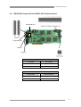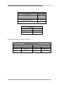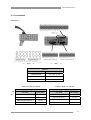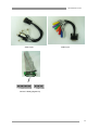
1
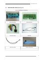
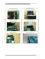
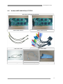
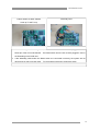
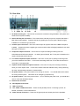
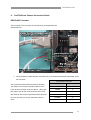
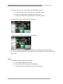
VENDOMA-MPG DVR (Digital Video Recorder) Hardware Installation Guide Version 1.00.00 © 2004 Aventura Technologies, Inc. VENDOMA DVR t INDEX 1. Features 4 2. Installation Notes 6 3. Products and Components 7 4. Install Capture Board 8 4-1. Vendoma MPG 12004 Board 8 4-2. Vendoma MPG 24008 Board Type A 10 4-3. Vendoma MPG 24008 Board Type B 12 4-4. Vendoma MPG 48016 Board Type A 14 4-5. Vendoma MPG 48016 Board Type B 17 20 5-1. Vendoma MPG 12004 Board 20 5-2. Vendoma MPG 24008, 24016 Board 21 5-3. Accessories 23 6. RS422/485 Converter 25 7. Vendoma System 27 9-1. Front View 27 9-2. Rear View 28 30 5. Pin number 8. P/T/Z Camera Connection Guide 2 VENDOMA DVR t Preface This guide book describes the individual hardware components and how to install them. For a description of the software and how to install it, please refer to the Installation and User Guide provided with your unit. This guide is for the following Aventura Technologies products: Vendoma MPG 12004, 24008, and 48016 capture boards. Board shapes and item names may be slightly different than those in this manual. We are looking forward to hearing your comments about our DVR. Should you have any questions, please contact us. E-Mail: [email protected] Telephone: 1 (800) 870 5330 Fax: (631) 434 7000 www.aventuratechnologies.com www.vendoma.com 3 VENDOMA DVR t 1. Features About Your Vendoma-MPG DVR 4, 8, or 16 Camera Input/Output Normal input condition: 75 Ohm, 1 Volt 1 4, 8, or 16 Sensor Inputs 4 channels, 4 sensors (16 sensors optional) 8 channels, 8 sensors (16 sensors optional) 16 channels, 16 sensors Note: DC 12 Volt power is required 1-16 Digital Outputs (Relay Outputs) 4 channels: 4 Relays (16 sensors optional) 8 channels 4 Relays (16 sensors optional) 16 channels 8 Relays (16 sensors optional) Note: DC 12 Volt power is required Sound Recording and Two Way Communications Capabilities 16 channel sound recording. Sound can be recorded locally on 16 channels; however, two-way voice communication can be done remotely on only one channel Multi-Viewing You can view 1, 4, 9, 10, or 16 cameras on your screen. A full screen option is also available. Pan/Tilt/Zoom/Focus Remote Control You can manipulate your Pan/Tilt/Zoom cameras via Vendoma Main. Auto Rebooting System If this feature is enabled, when the DVR detects a malfunction in the system, the system reboots and corrects the malfunctions. This is also called the Watchdog feature. 4 VENDOMA DVR t Motion Detection and Sensor Trigger You can set the DVR to record only when movements are detected, which saves storage space. Scheduled recording You can specify a recording schedule. Data Backup and Auto Backup Backed up data can be transferred to different media, such as DAT, CD, or DVD. You can also back up the data from a specific camera and view the date and time stamp on the footage. Like the scheduled recording, the data backup program can also be scheduled. Digitalized Video Search Recorded data can be played back digitally on one or more cameras at a time. By entering the date and the time, you can retrieve an image from the video. You can also edit, enlarge, save, and print images separately. Network Support (TCP/IP, ISDN, and PSTN Support) With network software, you can log in to Vendoma-Main remotely to view live recording, search and save video data locally, and even change the DVR’s settings. 5 VENDOMA DVR t 2. Installation Notes We recommend the following for ideal performance: Intel chip motherboards Intel Pentium 4 or equivalent (Nothing lower than a 2.0 GHz Celeron) 256 MB or more of RAM 80 GB or more hard disk space If you try to use a 160 GB hard drive or higher, your operating system should be updated with the latest service pack. Windows 2000 or Windows XP Screen savers and power management must be disabled System standby and energy saving mode for both the hard drive and the monitor should be disabled For sound recording DirectX 8.0 or higher must be installed ATI video cards are recommended, but any product higher than a 128 Radeon can be used 6 VENDOMA DVR t 3. Products and Components VENDOMA-MPG 12004 VENDOMA-MPG 24008 (120 Frames per second, 4 Channels) (240 Frames per second, 8 Channels) MPG 12004 Accessory MPG 24008 Accessory Type A MPG 24008 Accessory Type B MPG 48016 Accessory Type A MPG 48016 Accessory Type B The boards pictured above and their accessories may be subject to change by hardware upgrade. 7 VENDOMA DVR t 4. Install Capture Board 4-1. VENDOMA MPG 12004 Board MPG 12004 Board and Accessories MPG 12004 Board TV-Out, Sensor, Relay Video Input Audio Input Watchdog 8 VENDOMA DVR t 1 Connect audio input cable 2 Connect video input cable 3 Connect TV-OUT cable 4 Connect sensor relay cable 5 Connect Watchdog cable Assembly View Note: 1. After connecting the Watchdog cable, the other end of the cable must be plugged in to the Reset pin of the PC’s motherboard. The Reset switch from the PC must be plugged in next to the Watchdog on the DVR card. 2. If the Watchdog cable and/or the Reset switch are connected incorrectly, the system will not reboot and you may not have video. Try reconnecting the pins to restore the video. 9 VENDOMA DVR t 4-2. VENDOMA MPG 24008 Board Type A MPG 24008 Board and Accessories MPG 24008 Board TV-Out, Sensor, Relay Video Input cable Audio Input cable Watchdog 10 VENDOMA DVR t 1 Connect audio input cable 2 Connect video input cable 3 Connect TV-OUT cable 4 Connect sensor relay cable 5 Connect Watchdog cable Assembly View Note: 1. After connecting the Watchdog cable, the other end of the cable must be plugged in to the Reset pin of the PC’s motherboard. The Reset switch from the PC must be plugged in next to the Watchdog on the DVR card. 2. If the Watchdog cable and/or the Reset switch are connected incorrectly, the system will not reboot and you may not have video. Try reconnecting the pins to restore the video. 11 VENDOMA DVR t 4-3. VENDOMA MPG 24008 Board Type B MPG 24008 Board and Accessories MPG 24008 Board BNC Back panel Audio Input cable Watchdog Video Input cable Sensor & relay cable 12 VENDOMA DVR t 1 Connect Audio Input cable 2 Connect BNC cable 3 Connect Back panel cable 4 Connect Sensor Relay cable 5 Connect Watch dog cable Assembly View Note: 1. After connecting the Watchdog cable, the other end of the cable must be plugged in to the Reset pin of the PC’s motherboard. The Reset switch from the PC must be plugged in next to the Watchdog on the DVR card. 2. If the Watchdog cable and/or the Reset switch are connected incorrectly, the system will not reboot and you may not have video. Try reconnecting the pins to restore the video. 13 VENDOMA DVR t 4-4. Vendoma MPG 48016 Board (Board TYPE A) MPG 48016 Board and Accessories MPG 24008-1 Board MPG 24008-2 Board Video Input cable Audio Input cable TV-Out, Sensor, Relay 2EA Watchdog TV-OUT Loop 14 VENDOMA DVR t 1 Connect Video cable 2 Connect Audio cable (MPG 24008-1 & MPG 24008-2) (MPG 24008-1 & MPG 24008-2) 3 Connect TV-OUT cable 4 Insert Sensor Relay (MPG 24008-1 Only) (MPG 24008-1 & MPG 24008-2) 5 Connect Watch dog cable 6 MPG 24008-1 & MPG 24008-2 (MPG 24008-1 Only) Hook up TV-OUT Loop 15 VENDOMA DVR t Assembly View 1. After connecting the Watchdog cable, the other end of the cable must be plugged in to the Reset pin of the PC’s motherboard. The Reset switch from the PC must be plugged in next to the Watchdog on the DVR card. 2. If the Watchdog cable and/or the Reset switch are connected incorrectly, the system will not reboot and you may not have video. Try reconnecting the pins to restore the video. 16 VENDOMA DVR t 4-5. Vendoma MPG 48016 Board TYPE B MPG 48016 Board and Accessories MPG 24008-1 Board MPG 24008-2 Board Video Input cable Audio Input cable Watchdog TV-OUT Loop Sensor & relay cable 17 VENDOMA DVR t 1 Connect Audio cable 2 Connect BNC cable ( MPG 24008-1 & MPG 24008-2) ( MPG 24008-1 & MPG 24008-2) 3 Connect BNC cable 4 connect Back panel cable ( MPG 24008-1 & MPG 24008-2) 5 Insert Sensor Relay 6 Connect Watch dog cable ( MPG 24008-1 & MPG 24008-2) ( MPG 24008-1 Only) 18 VENDOMA DVR t 7 MPG 24008-1 & MPG 24008-2 Assembly View Hook up TV-OUT Loop 1. After connecting the Watchdog cable, the other end of the cable must be plugged in to the Reset pin of the PC’s motherboard. The Reset switch from the PC must be plugged in next to the Watchdog on the DVR card. 2. If the Watchdog cable and/or the Reset switch are connected incorrectly, the system will not reboot and you may not have video. Try reconnecting the pins to restore the video. 19 VENDOMA DVR t 5. Pin numbers 5-1. MPG4 12004 Capture Board Composite-OUT Composite-Out Video In Audio In Sensor & Relay(digital I/O) Pin name Pin number Sensor Input 0-3 1-4 Input Common 0-1 17, 18 Relay(Digital) Output 0-3 19-22 Output Common 0-1 23, 24 Watchdog Pin name Pin number Signal Ground 1, 3 Reset Signal 2, 4 20 VENDOMA DVR t 5-2. MPG 24008 Capture Board & MPG 48016 Capture Board Composite-Out Composite-Out Video In Audio In Video I/O Pin name Pin number Video In 1, 3, 5, 7 Signal 2, 4, 6, 8 Video I/O (Camera Connector) Group name Camera number A Camera 1-4 B Camera 5-8 21 VENDOMA DVR t Sensor & Relay(digital I/O) Pin name Pin number Sensor Input 0-7 1-8 Input Common 0-1 17, 18 Relay(Digital) Output 0-3 19-22 Output Common 0-1 23, 24 Watchdog Pin name Pin number Signal Ground 1, 3 Reset Signal 2, 4 Pin Arrangements of MPG 48016 are as follows: Video I/O (Camera Connector) MPG 24008-1 MPG 24008-2 Group name Camera number Group name Camera number A Camera 1-4 A Camera 9-12 B Camera 5-8 B Camera 13-16 22 VENDOMA DVR t 5-3. Accessories Back Board << Front >> << Rear >> Video I/o * Pig tail Pin name Pin number Signal Ground 1, 3, 5-29, 31, 33 Composite 2 Video in 0-15 4, 6, 8-30, 32, 34 Sensor & Relay 8 Channel Sensor & Relay 16 Channel Sensor & Relay(Digital I/O) Sensor & Relay(Digital I/O) Pin name Pin number Pin name Pin number Sensor Input 0-7 1-8 Sensor Input 0-7 1-8 Input Common 0-1 17, 18 Input Common 0-1 17, 18 Relay(Digital) Output 0-3 19-22 Relay(Digital) Output 0-3 19-22 Output Common 0-1 23, 24 Output Common 0-1 23, 24 23 VENDOMA DVR t Video Input 12345678G Audio Input GG4321 Sensor & Relay (Digital I/O) 24 VENDOMA DVR t 6. RS232 TO RS422/485 Converter This is the converter for controlling the Pan/Tilt/Zoom camera. 1. Connect the cable to computer serial Port. 2. You can select one of three Power connectors: - 1 : Power from Capture Board (+5V) 1 - 2 : Power from System Power Supply 2 - 3 : Power from System Power Supply 3 3. Connect data line from camera to this port. 4. Set the jumper switch for an RS-422 type Pan/Tilt/Zoom camera If you have an RS232 type Pan/Tilt/Zoom camera, connect the cable directly to the RS232 port. 25 VENDOMA DVR t RS-422/485 Pin number RS-422/485 Connector 1 2 3 4 5 6 Pin name Pin number - TxData 2 + TxData 3 - RxData 4 + RxData 5 Signal 1,5 26 VENDOMA DVR t 7. Vendoma System Assembly 7-1. Front Views 1. Cooling fan This fan removes the excessive heat generated in the system and enhances the system’s stability. 2. HDD LED When your hard disk drives (HDDs) are running, this light either blinks or remains steady). 3. Power LED This light is on when your system is powered on. 4. 3 ½” Floppy Drive (Optional) 5. CD-ROM or DVD-ROM 6. Reset switch 7. Power switch Push this button to power on the DVR. For normal operation, this switch should be used instead of the main power switch on the back of the DVR. Attention: Please do not use this power switch to stop the DVR Program. If you power off the DVR while it DVR Main is running, the current data and previously saved data may be damaged. Please follow the accepted directions for stopping the DVR program in the User Guide. 27 VENDOMA DVR t 7-2. Rear View 1. AC Power Cooling fan – This fan also removes the excessive heat generated in the system and enhances the system’s stability 2. Sensor & Relay I/O connectors – This is the sensor and relay-out port for systems that have a BNC back panel installed. Systems that have a pigtail type connector (also called a Dongle) installed do not need this type of sensor. 3. Camera input connectors – This is the camera input for systems that have a BNC back panel installed. Systems that have a pigtail type connector (also called a Dongle) installed do not need this type of In/Out port. 4. Composite output connector – This is the TV-out port for analog monitoring found on CAP2X6016 and CAP12016 boards. On other types of boards, the TV-out port is located on the capture board (see part #6 above). 5. Live video composite output connector – This is the TV-out port for analog monitoring when you use a Vendoma Live board. In this case, the analog views from TV-out are the same as in multi-view on Vendoma Main. 6. Capture board composite output connector – This is the TV-out port for analog monitoring when you use a capture card. In this case, camera views are attained one by one by switching all of the channels being viewed on Vendoma Main. 7. AC power switch – This power switch is for turning on the unit. You should not use this switch for turning off the system. This switch is for emergency purposes only. 8. AC power socket – This is the power socket. Prior to inserting the power cord, you should take care to notice the allowable voltage. 9. PS/2 mouse connector 10. PS/2 keyboard connector 11. USB connectors 12. LPT, COM1, COM2 connectors – These are the parallel ports for connecting a printer, an RS485, an RS422, or other serial device. 13. Game, Sound connectors – These are the game ports and sound ports for the speakers. 28 VENDOMA DVR t 14. Video output connector – This is for monitor (VGA) connector. 15. Pan/Tilt connector – If your system was equipped for Pan/Tilt/Zoom controls, then you have one of these connectors 16. LAN connector Please note that all DVRs must be connected an Uninterruptible Power Supply (a UPS) with line conditioning. At least a 550VA (1530 minutes) or more is recommended. 29 VENDOMA DVR t 6: Pan/Tilt/Zoom Camera Connection Guide RS232/485 Converter This converter is for the control of Pan/Tilt which are supported in the RS232/485 Port . 1. Connect DB9 pin cable between the serial Port in the motherboard board and RS232 port in this converter. RS-422/485 Connector This is what the RS 232-485 Connections look like, Pin name Pin number you need to connect the Controller Cable from the Ground 1 P/T/Z to this connection as shown above (RX+ and - TxData 2 RX-).When you do this, make sure that your P/T/Z’s + TxData 3 Dip switches are set to the specified camera Channel - RxData 4 and com port that you chose, otherwise it will not + RxData 5 Ground 6 work* 30 VENDOMA DVR t 2. For power connection, you may utilize one of the following 3 sources. - 1 : Connect the power cable from power unit to socket No.2 (+5V) - 2 : Connect the power cable from power unit to socket No.3 - 3 : Connect power cable from capture board to socket No.1(Option) 3. Set the jumper as follow, on RS-422 Pan/Tilt settings Set the jumper as follows, on RS-485 Pan/Tilt settings. 4. Connect the cable from RS485/422 port to PTZ driver as displayed in the following figure. 5. If you use the PTZ supported with 232 Pan/tilt, connect the cable from the PTZ to PC serial port directly. *NOTE: P/T/Z Cameras require 3 different wiring types. A. Coax Cable (RG59/RG6) –For Video B. Power Wire(1 Pair)-For AC 24/DC 12 Volt Power C. 1 Pair Wire (Positive and negative wire)-For P/T/Z Controls 31