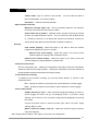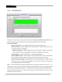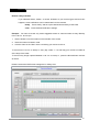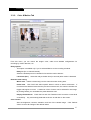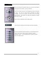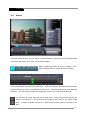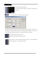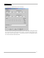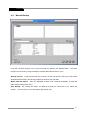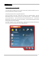
1
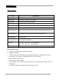
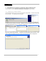
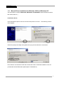
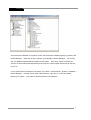
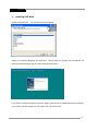
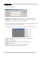
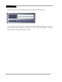
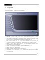
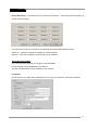
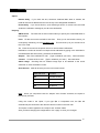
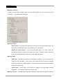
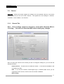
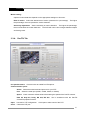
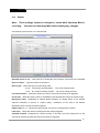
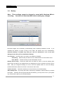
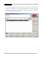
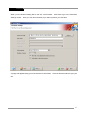
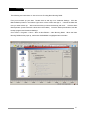
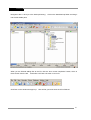
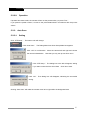
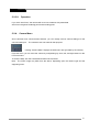
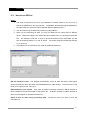
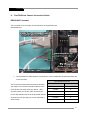
225 Vendoma-MPG DVR (Digital Video Recorder) Installation and User Guide Version 1.00.00 Vendoma © 2004 Aventura Technologies, Inc. Table of Contents Foreword 3 Features and Specifications 4 1. Driver Installation 6 1-1 Install Driver for Win 2000/XP (Automatic) 7 1-2. Install Driver for Win 2000/XP (Manual) 8 2. Installation of Program 10 3. Configuration 13 3-1. Disk Tool 14 3-2. System 16 3-3. Camera 23 3-3-1. General 23 3-3-2. Scheduling 25 3-3-3. Color & Motion 27 3-3-4. Pan/Tilt 28 3-4. Sensor 30 3-5. Backup 31 3-6. User Admin 33 4. Operation of program 37 4-1. Main Program 37 4-2. Search Program 38 4-3. Back up manual 43 4-3-1. Using Nero 4-4. Backup Viewer 4-5. Authentication Tool 5. Appendix 45 50 51 52 5-1. DVR Management 52 5-2. Pan Tilt (Sample) 53 5-3. How to use DB Tool 57 5-4. Direct Web 58 6. Pan/Tilt/Zoom Camera Connection Guide 61 2 Vendoma Foreword This manual describes how to use the Vendoma MPEG4 DVR Boards and their corresponding software. Following the commercial class DVR, we’ve released a 2nd generation DVR system which uses a hardware compression codec board. With the MPEG4 hardware codec, real time display and real time recording are attainable, both of which will be prevalent in the next DVR market. It is generally known to those in the DVR profession that MPEG4 technology is the best choice among presently introduced codec technology. The main advantages are better image quality, faster transmission, higher resolution, and multiple audio channels support. Looking at the features that are available with the software codec, you will find that the same features are also available with the hardware codec board. The most remarkable differences between the hardware and the software codec types are high speed transmission by remote viewings and multi-support in two way communications. Thanks to small-sized files, these features are possible. Moreover, it allows you to utilize remote viewing by high resolution (704 x 480 at NTSC) though the speed becomes slower. Since there are still many countries that only have dial-up modem connections, we’ve engineered our application to be compatible with modem connections. As the actual communications facilities are quite different for those equipped with 56 Kbps modem than those equipped with 100 MB LANs, it is very difficult to make software that works perfectly for both environments. We are striving to release the best solution for remote viewing without utilizing any commercial server. We are looking forward to hearing your comments about our DVR. Should you have any questions, please contact us. E-Mail: [email protected] Telephone: (800) 870 5330 Fax: (631) 434 7000 www.aventuratechnologies.com www.vendoma.com 3 Vendoma Features About Vendoma MPG 4, 8, or 16 Camera Input/Output Normal input condition: 75 Ohm, 1 Volt 1 4, 8, or 16 Sensor Inputs 4 channels, 4 sensors (16 sensors optional) 8 channels, 8 sensors (16 sensors optional) 16 channels, 16 sensors Note: DC 12 Volt power is required 1-16 Digital Outputs (Relay Outputs) 4 channels: 4 Relays (16 sensors optional) 8 channels 4 Relays (16 sensors optional) 16 channels 8 Relays (16 sensors optional) Note: DC 12 Volt power is required Sound Recording and Two Way Communications Capabilities 16 channel sound recording. Sound can be recorded locally on 16 channels; however, two-way voice communication can be done remotely on only one channel Multi-Viewing You can view 1, 4, 9, 10, or 16 cameras on your screen. A full screen option is also available. Pan/Tilt/Zoom/Focus Remote Control You can manipulate your Pan/Tilt/Zoom cameras via Vendoma Main. Auto Rebooting System If this feature is enabled, when the DVR detects a malfunction in the system, the system reboots and corrects the malfunctions. This is also called the Watchdog feature. 4 Vendoma Features (continued) Motion Detection and Sensor Trigger You can set the DVR to record only when movements are detected, which saves storage space. Scheduled recording You can specify a recording schedule. Data Backup and Auto Backup Backed up data can be transferred to different media, such as DAT, CD, or DVD. You can also back up the data from a specific camera and view the date and time stamp on the footage. Like the scheduled recording, the data backup program can also be scheduled. Digitalized Video Search Recorded data can be played back digitally on one or more cameras at a time. By entering the date and the time, you can retrieve an image from the video. You can also edit, enlarge, save, and print images separately. Network Support (TCP/IP, ISDN, and PSTN Support) With network software, you can log in to Vendoma-Main remotely to view live recording, search and save video data locally, and even change the DVR’s settings. 5 Vendoma Specifications: Item Specification Camera Input 4, 8, or 16 channels Sound Input 4 (4ch BD), 8 (8ch BD), 16 (16ch BD) Sensor Input 4 (4ch), 8 (8ch), optional 16 (16ch) Digital Output 4 (4ch), 4 (8ch), 8 (16ch), 16 optional Composite Output 1 Channel (Switching) Compression Codec MPEG 4 (Hardware) Recording Mode Watch, Normal, Motion Detection, Sensor, Event Scheduled Recording Remote Control Full remote control PSTN, ISDN, ADSL, LAN and TCP/IP Back-Up Media DAT, CD, DVD Pan/Tilt/Zoom/Focus RS-232/422/485 Interfaces Resolution 352 x 240, 704 x 480, 704 x 240 (NTSC) 352 x 288, 704 x 576, 704 x 288 (PAL) Image Format YUV We recommend using: At least an Intel 865 chipset motherboard or higher. 256MB or more RAM ATI video cards are recommended, but any product higher than a 128 Radeon can be used Intel Pentium 4 or equivalent (Nothing lower than a 2.0 GHz Celeron Windows 2000 or Windows XP. Screen savers must be disabled. System standby mode, monitor energy saving mode, and hard disk energy saving mode must be disabled. For sound recording, an amplifying microphone should be used 6 Vendoma 1: Automatic Driver Installation for Windows 2000 and Windows XP The same driver is used for MPG12004, MPG24008, and MPG48016 capture boards. 1-1: Install Driver for Windows 2000/XP Insert the MPEG4 capture card into a PCI slot and power on the machine. Insert the CD provided with your system. The following screens will appear. To install the driver manually, click Cancel. Browse to the driver installation folder on your CD drive (default path E:\Driver_2k_xp). Double click “installer.exe.” Click next to begin driver installation. “Installer.exe” will automatically detect the device. Click Install. When the installation process is complete, reboot the DVR to save the configurations. 7 Vendoma 1-2: Manual Driver Installation for Windows 2000 and Windows XP The same driver is used for MPG12004, MPG24008, and MPG48016 capture boards as well as both NTSC and PAL.) Install Basic Driver: Insert the MPEG4 capture card into a PCI slot and power on the unit. The following screens should appear: Follow the prompts and keep clicking Next until you get to the “Browse” screen below: Click “Browse” and locate the folder that contains the driver for Windows 2000/XP on the CD provided with the MPEG4 board (default path: E:\Win2kDriver) 8 Vendoma Once the driver installation is complete, confirm that it has been installed properly by checking the Device Manager. Right click on My Computer, go to Manage > Device Manager. You should see your MPEG4 Capture Boards installed on the system. Each entry equals 30 frames per second, so two entries equals 60 frames per second, four entries equals 120 frames per second, and so on. If your system does not detect the new device, go to Start > Control Panel > System > Hardware > Device Manager. Find the device under “Other Devices,” right click on it, and click Delete. Reboot your system. Your machine should detect the new hardware. 9 Vendoma 2: Installing DVR Main Double click setup.exe. The following screen will appear: Select your preferred language and click Next. Simply follow the prompts (we recommend you leave the default settings) and click “Next” through the prompts. If you want to install the program for NTSC, simply leave that as the default setting and click Next. If you wish to use the program for PAL, select “PAL” and click “Next.” 10 Vendoma The following screen will appear: USER NAME – Enter the desired username for the person who will be the DVR’s administrator. PASSWORD – Enter the desired password for the person who will be the DVR’s administrator. Confirm P/W – Type the password again to confirm correct spelling. Click OK to finish the setup. Several icons will be generated on your Windows desktop. Reboot the system to save the settings and finalize the installation. After rebooting, you will see the following programs under Start > Programs > Vendoma DVR: Auth Tool – A program for discerning whether or not a stored image has been altered. AVI Viewer – View AVI files Backup – Data backup program. Backup Viewer – A search program used to view previously backed up data. DVR Main – Main program. DVR Search – A program used to search for previously recorded data. DVR Setting – A program used to change the DVR’s settings. 11 Vendoma Any time you click on any of the above programs, the following screen will appear: As you can see, in order to alter, view, or back up any data recorded by the DVR, you must sign in with the administrator’s username and password. This is for security reasons. Any time someone logs in, the events are stored in a log file. 12 Vendoma 3: Configuration Click on "DVR Setting." The following screen will appear: Disk tool – A program wherein you can create a database file system specifically for storing and organizing recorded images. The Vendoma program creates its own file system so that the large amounts of DVR data will be treated safely in a dedicated disk area. Note: Prior to operating your DVR for the first time, databases must be created. The Vendoma program will not record video data unless you designate a database for storage. System – Change various settings, including initial view; network connecting options, automatic rebooting, site information, etc. Camera – Camera setup including digital outputs, scheduled recording, etc. Sensor – Sensor setup and link options. Backup – Automatic backup and manual backup settings. User admin – Here the Administrator can add and delete users and set the level of authority each user will have. 13 Vendoma 3-1: Disk Tool Note: These settings cannot be changed or saved while Vendoma Main is recording. You must exit Vendoma Main before making any changes. Total – The total capacity of hard disk space (in MB) in the selected hard drive. Used Disk – The amount of hard disk space (in MB) already used. Usable Disk – The amount of hard disk space (in MB) available to create more databases. Max Volume – The maximum amount of hard disk space (in MB) available to create a volume. Add Volume – The amount (size of volume) to be added. Delete Volume – Deletes all of the volumes from the selected hard drive. Clear Volume – This will delete all of the information in the created volume in all drives. This procedure cannot be undone! Before clearing the volume, be sure to back up your data onto a CD, a DVD, or other media. Create Volume – Create a volume of the size specified in “Add Volume” What is a Volume? A volume is a unit used in the Vendoma database file system. One volume equals 65MB of hard disk space. All image data is recorded in volumes. Once a volume is full, the program stores newly-recorded data at the beginning of the volume by overwriting the oldest data. Thus, important data must be backed up prior to overwriting. The next page describes how to create volumes using Disk Tool. 14 Vendoma How to create volumes: Note: Try not to create volumes on the same partition that hosts your operating system. Try to create all of your volumes on the second partition. Volumes can be created on multiple partitions. For this example, we will use the D: drive (since the C: drive hosts the operating system). Highlight the D: drive and notice the amount of hard disk space available for volumes In “Max Volume.” In the example below, the amount of MB available is 47. Enter 47 into the white box and click the Add button. Click “Add Volume” at the bottom of the screen. A confirmation box will pop up asking you if you are sure you want to create a volume that size. Click OK. The system will create and format the volume for you. Repeat the process for any remaining hard disk space. Note: You must create the volumes no larger than 2000 at a time. Creating volumes 2100 MB or larger will cause your system to malfunction. For instance, if the amount shown under Max Volume is 2400, create a volume sized at 2000, then create a second volume sized at 400. Prior to adjusting the sizes of the database(s) or deleting data, you must stop the DVR program. Do not attempt to clear data from the database while the DVR is recording. 15 Vendoma 3-2: System Note: These settings cannot be changed or saved while Vendoma Main is recording. You must exit Vendoma Main before making any changes. Site Information: Site Name: Enter the name of the site. This is the name that shows when you get email notifications. Site Location: Enter the address of the site. Network: Allow remote connections: Check this box if remote viewing has been enabled. Code: Enter a unique 10-digit code made up of both alphabetic and numeric characters. Method: If you are using a modem, you must configure Remote Access. Note: You should configure “incoming connections” under Windows 2000/XP. For further details, refer to the appendix in the Vendoma-Net Manual. IP/Num (Code): This is the destination (on a remote system) for event notification. Type the IP address for TCP/IP mode or the telephone number if you’re using a modem. However, if you’re using an IP Server, enter the code of the remote PC for notification. Note: Do not confuse this code with the code in “Use IP Server.” The Code in IP/Num (Code) is of the remote PC that will receive event notifications from the DVR. The Code in “Use IP Server” is the code of the DVR. 16 Vendoma Use IP Server: If you’re using an IP server and you have a dynamic (changing) IP address, it is more convenient to access the network without having to frequently check and/or change your IP address. This can be achieved by assigning a unique code to the DVR and then configuring that code into the DVR. Check the box for “Use IP server” and then click “Properties.” You will see the following: IP Server: In order to use this feature, please consult the distributor on how to use it. For this application, you must have a static IP address assigned to the IP server. Notify Interval: Notification will be sent just once in this time interval. Any other events occurring within this time will not be sent. NOTE: The code, maximum 10 digits, must be made with only letters and numbers and is case-sensitive. Should you create the exact same code twice, the code created the latest will overwrite the other. Remote notification of events: Enables event notifications to be sent anywhere if a trigger is detected. Check the box if you want to allow notification to be sent to a network PC, as long as you know the IP address and the Vendoma-Net program has been installed on that PC. Log Write: Logging information (by default) is stored in the C: drive. Checking this box enables relevant events to be logged and stored in the c: directory. Check the boxes for the events you wish to be logged. Screen: Initial screen: Sets the number of camera shots to be shown on the screen when you start the program. For instance, if you have a 16-channel system, and you choose the 9screen option, when you start Vendoma Main, the screen will be split into a 9-camera multi-view and you will not see the remaining 7 cameras. Large Screen: Makes your initial view a large screen view automatically. If you choose not to enable large screen mode, you can hit F5 to switch to large screen view. CCTV Monitor auto switching interval: Sets the interval time for camera switching through the Composite-Out port. Only one channel shot is shown on the screen at a 17 Vendoma time, then the view changes to the next camera in the cycle. PC Screen auto switching interval: Sets the interval time between the split screen shot and next split screen shot when you click the auto switching button. Auxiliary Functions: Keyboard lock (Windows key disable/enable): Disables the Shift, Ctrl, Alt, and the Windows Key on the keyboard. Enable hardware watchdog (Auto Reboot): Reboots your system when something abnormal happens. Note: For the watchdog feature to work, make sure Vendoma Main (“main.exe”) is in your startup folder. Audible alert on video loss: Makes a beeping alarm go off whenever video loss occurs. Schedule auto reboot of DVR: Here you can set the day and time that you want the DVR to reboot automatically, regardless of watchdog functions. Note: Your DVR must be rebooted at least every 30 days to avoid possible malfunctions, such as memory leaks, sluggish performance, etc. Creating a schedule for your system to automatically reboot will help you avoid these malfunctions. 18 Vendoma Sound Recording: Check this box if you want to record sound. Select the camera number you want to record sound on. You can search sound on a remote PC by selecting the channel that stored the sound. Select all: Click this to select all cameras for sound recording. Clear all: Click this to disable sound recording on all cameras. Sound Recording Notes: For sound recording, DirectX 8.0 or higher is recommended. Do not forget to use the amplification microphone. Two-way communication is only available on one channel. Use E-mail: Check the box if you want event notifications to be sent to you via e-mail, then click Properties. 19 Vendoma Option: Reboot Notify: If you check this box, whenever Vendoma Main starts or restarts, the DVR will send its IP address and the time of day to the designated IP address. Event Notify: If you check this box, upon detecting a sensor or motion event, the DVR sends the notification message by e-mail to the destination. Property: SMTP Server: The DVR will not send e-mail unless you specify the e-mail addresses of the recipient. From: Fill the account the mail will be sent from. Even you do not know the name, you must specify something, such as [email protected]. This will show up in your e-mail box as the “From” field. To: Enter the account of the person who is to receive these notifications. Notification e-mails can be sent to multiple e-mail addresses by typing in the individual email addresses with semicolons (;) between the addresses. Subject: Title of the notification e-mail. (Type in whatever you want.) See note below. Content: Contents of the e-mail. (Type in whatever you want.) See note below. Attach image: Checking this box enables image clips to be attached to the e-mail whenever an event notification is sent. Send Interval: Mail will be sent just once in this time interval. Reserved word Contents $$0 Camera Number $$1 Events $$2 Time $$3 IP address Note: When you compose the text for “Subject” and “Content” as above, the cipher to the left may be used: Using the codes in the cipher, if you type $$0 in composition text, the $$0 will automatically be converted to the relevant camera number in the sent mail. This cipher is ONLY applied to the “Subject” and “Content” fields. After you finish changing the configurations, click “Apply” to save your changes. 20 Vendoma Warning on disk full: In order to get an alert message when your hard disk is filling up check this box and click “Properties.” The following box will pop up: Warning at value: Last volume: If you have more than one volume and you check this radio button, you will receive your notification when you are filling up your last volume. Specify the used percent: If you select this radio button, you must choose the percentage at which you want to be notified, up to 99%. The target volume, mentioned here, may be changed subject to the next option (“Warning at disk.”) Warning at disk: Total disk: Total disk is the amount of the storage on the DVR. This accounts for ALL storage on the entire DVR. This amount is the total amount of all volumes, hard disk drives, and logical drives added together. You will receive the warning when all available space on the drive is full. Current disk: Current disk is the amount of storage in the disk that’s currently highlighted. This reflects the space for just one drive. Warning at a term: This feature gives the alarm in advance, before the limit hgas been reached. 21 Vendoma You set the number of days in advance that you want to be notified. First, determine the length of time (in days) that you wish to save DVR data, and how far in advance you want to be notified before the disk is full. When you want to be warned at the preset time before the hard disk is full, enter the desired time in hours and minutes. Start date: The starting day for recording. Warning time: This is the warning time (hours and minutes) on that calendar date to be due after “Saving duration (days)” since the saving has been started. Saving duration (days): The target number of saving days. Example: When the “Start date” is set at 2003/11/25, the “Warning time” is set as 09:00, and the “Saving duration (days)” is set to 10 days, then the warning goes off at 2003/12/5 at 9:00. Saving options on Warning: Select whether or not you want to allow your DVR to overwrite image data when the disk is full, or if you want to receive a message before it starts overwriting. Save on warning: Checking this box allows old data to be overwritten after the volumes have been filled. No save on warning: Checking this box does not allow the old files to be overwritten. When the disk is full, recording will stop, regardless of the recording schedule. Setting log off timeout: This is the time (in minutes) that you can be in the system before it logs you out. Any and all configurations made while you were logged in will be saved when you are logged out. If you need to make more configurations, you will need to log in again. 22 Vendoma 3-3: Camera Select All: Clicking this button applies the settings from the selected camera (in the above picture, camera #1) to all of the other cameras. This applies all of the settings in “General,” “Schedule,” “Color & Motion,” and “Pan/Tilt.” 3-3-1: General Tab Note: These settings cannot be changed or saved while Vendoma Main is recording. You must exit Vendoma Main before making any changes. After you select the number of the camera you wish to change the settings for, you can alter the settings as follows: Enable Camera: Check this box to enable the camera. If the camera is disabled, it will not capture any data. Note: If you see the Aventura Technologies logo in Vendoma Main where you are supposed to see a camera, check to see if the camera is disabled. Basic setting: 23 Vendoma Camera name: Type in a name for that camera. You can make the name of that camera display on the main program. Resolution: Select the desired resolution. Adjust camera frame rate: Maximum averaged frame rate: Set the recording speed as the maximum frame per second rate that the board can attain. Select frame rate by camera: Manually set the number of frames per second at which you want the DVR to record. You can choose to have the DVR record at 1 frame per second or at 30 frames per second, but whichever number you select will be lower than the rate the board is capable of attaining. Security: Hide camera (Display): Select this option if you want to block the camera images from appearing on the PC’s monitor. Remove from CCTV display: Select this option if you want to block camera images from going to the composite-out port. Remove from network display: Select this option if you want to block the camera images from being viewed on Vendoma-Net. Compress format & rate: Set the compression rate. Setting the compression rate higher slows the transmission speed but improves the image’s quality. Setting the compression rate lower speeds up the transmission speed but decreases the image’s quality. Pre & Post alarm recording: To enable pre & post alarm recording, you must first select “Motion” or “Sensor” in the Scheduling menu. Pre: Number of frames to record prior to a motion detection or sensor trigger. Post: Number of frames to record after a motion detection or sensor trigger. Event notify method: Audible warning on event: When event has triggered recording (a motion or sensor trigger), the alarm can go off (beeping) and/or a “red mark” image warning can be sent out. This “red mark” image warning disappears by clicking the screen. Use the drop-down menu to select the alarm type, either “red mark” image warning, Beep, or both. When a video loss happen, relay out: Select the number of relay-out when a video loss happens. After changing these settings, click "Apply" to save the new configuration. 24 Vendoma 3-3-2: Scheduling Tab On this menu, select each camera and set the desired time by hour and day-of-the-week for that camera to record (or choose “Select All” to apply those settings to all of the cameras.) Recording schedule: Normal (Lime green): All images captured from the camera are recorded. Sensor (Yellow): Record images at the set frame rate in “adjust camera frame rate” only when the sensor is triggered. Motion (Turquoise): Record images at the set frame rate in “adjust camera frame rate” only when more than set degree of movement is detected on the camera. Display (White): No recording is done. Video is simply displayed. Sensor & Motion (Pink): Record images at the set frame rate in “adjust camera frame rate” when the sensor is triggered or when movement is detected by the camera. Normal & Event (Orange): Record images at the set frame rate in “adjust camera frame rate” when no events have happened, but record with full frame rate within the card’s capability when an event happens. Note: You must select the recording schedule before you set the day and time it is to occur. For example, if you want to record only motion detection on Tuesdays from 12pm – 8pm, select Motion, then choose your day and time settings. The blocks will then change to the corresponding color. The picture shown above is set to record every image the camera captures on Sunday through Saturday for 24 hours per day. 25 Vendoma Remote notify schedule If you selected Sensor, Motion, or Sensor & Motion as your event triggers and an event happens, event notifications can be transmitted over the network. Notify: Press “Notify” and set up the desired time and day-of-the-week. Clear: Erase selected notification settings. Example: You want to record only motion-triggered events on camera number 5 every Monday from 7:00 a.m. to 8:00 p.m. 1. Select camera 5 from the buttons on the left side of the screen 2. Select the button for Motion mode 3. Click the chart on the "Mon" line at 7 and drag your mouse to the 19. To record from 7:00 a.m. to 8:00 p.m. every day, select 7 – 19 and drag your mouse to include all of the days of the week. To record every image captured between 7:00 a.m. to 8:00 p.m., press the Normal button and set as above. Please note that the DVR’s time settings are in military time. 26 Vendoma 3-3-3: Color & Motion Tab From this menu, you can control the image’s color, make more detailed configurations for recording by motion detection, etc. Relay options: This option is available only if you’ve selected Motion on the recording schedule. Relay 1-8 (for 16 channel boards): Select the desired ports to be enabled in line with the motion detector. Latch time (Sec): Select the relay activation time (in seconds) after motion is detected. Detection area setting: Whole area: Detect movement(s) over the camera’s entire viewing area. Partial area: Click "Add" and select specific areas in which to detect movements. If movements are detected more than the pre-set movement ratio, the camera considers it a trigger and begins to record. A maximum of ten of zones can be selected in one image. By clicking Delete, you can delete the preset detection area. Display detected area: Check the box and click "Detection test" to test the current level of sensitivity. Any movement(s) detected are shown as red dots on the screen. Color Control Alter the brightness, contrast, saturation, and hue of the camera image. Click "Default Value" to return all settings to the default values. 27 Vendoma Motion setting: Optimum motion detection depends on the appropriate settings on this menu. Rate of motion: Select the desired rate of motion (measured in a percentage). The higher the percentage, the more precise the motion detection. Sensitivity adjustment: Set the sensitivity of motion detection. The higher the percentage, the more sensitive the motion detection. The DVR will notice color changes between objects and back ground. 3-3-4: Pan/Tilt Tab Use pan/tilt camera: Check this box to enable Pan/Tilt options. Communication option: Select: Select the make/model and protocol for your PTZ. Port: Select the serial port (COM1, COM2, COM3, or COM4) Speed: Check camera’s default value before setting the speed of the Pan/Tilt camera. Data bit, Stop bit, Parity, RS 232, RS 422: Set in accordance with the Pan/Tilt camera’s equipment manual. Open: Use this for PTZ configuration. Click Open to take control of the PTZ. Close: Closes the PTZ port. 28 Vendoma Speed: P/T: Speed adjustment for the Pan/Tilt (depends upon the camera’s features.) F/Z: Speed adjustment of Focus/Zoom AP: Speed adjustment of Auto Pan. Camera menu: Clicking this button brings up the PTZ activation menu. Functions: Move the camera up, down, left, or right; focus in or out, and zoom in or out. Auto Scan (this is applicable to only the LPT-A100L). Auto scan: Scans from “start scan” to “stop scan” per the presets you made. Start scan: Define the starting position of the PTZ. Stop scan: Defines the ending position of the PTZ. Preset: Preset setup: Make the PTZ memorize appointed locations to view or scan, up to 20 locations maximum. Example: You want to program preset number one: Click “preset setup” and press the button for preset number one. Move the PTZ to the desired location and stop. Then click both of the buttons for preset number one and “preset setup.” Notes: 1. Depending upon the type of PTZ you have, features such as auto scan, camera menu, preset, speed, etc. may be different or not available. To see if these features are available on your PTZ, please refer to the manual provided with your PTZ. 3. If you see a port open error message on Windows XP, you may have to change the network port to 3003. To do this, go to your Windows desktop. Right click on Vendoma Main and click Properties. Click “Find Target.” Double click on “start.exe” and enter your username and password. Enter your username once and password twice, then go to the Advanced tab. Alter the ports as necessary and click OK to save the settings. 29 Vendoma 3-4: Sensor Note: These settings cannot be changed or saved while Vendoma Main is recording. You must exit Vendoma Main before making any changes. The following picture shows a 16 channel DVR: Selected sensor to use: Check the box to enable the use of sensors; uncheck the box to disable. Sensor location: Type the location of the sensor. Sensor type: Select the type of sensor being used: 0: N.O: N.O means “Normally Open.” The circuit is always open. 1: N.C: N.C means “Normally Closed.” The circuit is always closed. Connected camera: Select the camera you want to record when the sensor is triggered. Check time: Make the sensor check for availability at the selected time interval (in milliseconds). Emergency notify: Regardless of “Remote Notify Schedule” (in camera setup), if you checked “Remote notification of events” in “System Setup,” notification can be sent to the desired destination when a sensor has been triggered. Output relays 1 – 4: Choose the relay number you want to be linked with the sensor. Latch time: Select the sensor activating time after sensor triggered. Camera#, Preset#: Designate the camera number in line with PTZ and Preset point so the camera can watch that preset point when the sensor is triggered. 30 Vendoma 3-5: Backup Note: These settings cannot be changed or saved while Vendoma Main is recording. You must exit Vendoma Main before making any changes. Recorded images can be backed up automatically when a Backup Schedule is made. If you schedule the backup in terms of days of the week, the backup will occur automatically. Automatic Backup is enabled only when you click the "backup.exe" icon on the main Settings screen after you’ve scheduled the backup! Use schedule: Check this box if you want to use a Backup Schedule. Scheduling: Select the day of week from the “schedule table” from the bottom menu. Hour, Minute: Choose the time you want the Backup to start. Backup device setup: Choose the hard drive and folder on which to save the backup data. Data can be recorded on any media shown as a storage drive on the computer as well as a CD or DVD. After you change the settings, be sure to click the "Update" button to save the settings. Updated information will then be shown on the chart on the screen. Camera selection: Select the cameras you want to back up on the selected day. Start backup timer: By clicking this button, the Back-Up schedule is valid whenever you reboot the system. If backup was set up and launched successfully, you may see an icon in your system tray, at the bottom right of your Windows desktop. 31 Vendoma << Example >> Backup (automatic) at 8:00 p.m. (20:00) every day: If you set the backup time as 20:00 every day, then actual backup will carry out every day from 20:00:01 of yesterday, to 20:00:00 of today. Actual backup execution starts from the time the previous backup was done and ends at the time when the backup is set to begin. This is the Automatic Backup feature. Manual backup gives you the option of setting the backup to any day and time that you want. Backup at 8:00 p.m. (20:00) every Saturday: If you have backup settings as 20:00 every Saturday, then backup will perform every Saturday from 20:00:01 of last Saturday to 20:00:00 on the current Saturday. When you’ve finished scheduling the backup, be sure to run the Backup program on the main DVR Settings screen (a turquoise button found at the bottom right of the screen). If you fail to do so, the scheduled backup will not work automatically. 32 Vendoma 3-6: User Admin Note: These settings cannot be changed or saved while Vendoma Main is recording. You must exit Vendoma Main before making any changes. User accounts can be added, deleted, or modified only by the DVR’s administrator. New User: Enter the desired username. Password and Confirm password: Enter the desired password for that user. Security Level: Select the level of the authority. Note that when you change the security level, the boxes in the Authority section automatically change to reflect that level of authority. However, you can customize each level of authority for each user by adding or removing privileges. Authority: Assign a level of authority to the user. Decide whether or not you want to allow that user to change the DVR’s settings, back up the information, shut down/restart the DVR, search previously recorded data, control the PTZ camera, or access the DVR through Vendoma-Net. After entering all of the information for the new user, click "Add/Modify" to save the settings. To delete an operator, select the user name in the bottom section and click "Delete." 33 Vendoma 4: Operating Vendoma Main 4-1: Main Program NOTE: DVR settings must be completed before attempting to operate Vendoma Main for the first time! Press F5 to toggle full screen mode. 34 Vendoma This button can be used for emergency recording regardless of whether or not you’ve set a recording schedule in Vendoma Settings. Click here to run a “Smart Search.” Click one of the split image profiles for multi-viewing. The screen can hold up to 33 different camera images for a 32 channel system, 16 images for a 16 channel system, and so on. The circular arrow allows you to cycle through camera images. The circular arrow with an A in it allows you to “auto-change” – meaning your cameras will automatically cycle themselves every few seconds. You can achieve full-screen viewing by pressing F5 or hitting the "+" button. When in full screen mode, you can return to menu view by hitting F5 or clicking the "-" button. F5 will enlarge the screen from menu mode to full-screen mode with the split image profiles at the bottom. Hitting F6 will enlarge the screen to complete full screen mode, with no menu options shown. On the 6- or 10-view split image screen, if you want to make camera number one the image in the big portion of the screen, simply right click on camera number one. Camera one will then be showing in the large image location. The blue and orange lights show the display/record status of each camera. No lights mean that the camera is not recording. Solid lights on the bottom row show that the images from the camera are being recorded. The solid lights on the middle row indicate that images are coming from the camera. The camera number is shown above the light. Blinking lights, if any, on the middle row indicate that the camera has not been enabled in Vendoma Settings. This shows the status of the four digital outputs. A depressed button means that the sensor relay has been activated; a raised button means the relay has not been activated. You can also manually activate the sensor 35 Vendoma The current date and time appears on the screen. The numbers and the circles on the bottom part of the screen indicate the total number of volumes and the number of volumes being used. The left tab activates the Search program while Vendoma Main is still running. The center tab activates Vendoma Settings while Vendoma Main has been temporarily paused. The right button exits Vendoma Main. Click "CAMERA" to open the Camera Control menu. Click "IMAGE" to open the Image Control menu, in which you can edit the brightness, contrast, etc. This brings up the login box where you must enter your username and password. You can manage DVR features as long as you have the authority to do so. Click here to open the menus for PTZ and image control. The picture at left shows the menu for DVRs that support PTZs with preset and tour functions. This display may differ depending on the type of camera you have. The picture at right shows the preset numbers. By clicking the preset number (if you’ve already programmed them) will move the camera to the designated spot. Instructions for setting up these presets can be found in section 3-3-4 of this book. Clicking the Tour button makes the PTZ move to all of the locations in order. The tour will run through all presets that have been set up, from 1 through 20. 36 Vendoma The circle of buttons at the bottom allows you to move the PTZ camera in the directions of the arrows. A/P is for Auto Pan. The circle of buttons at the top is for selecting the camera and altering the view. The zoom and focus buttons manipulate the camera accordingly. Use the up and down arrow tabs to select the desired camera number. The number in the center circle indicates the camera that’s being controlled. Power1, Power2, and Power3 are for auxiliary power. Click this button to bring up the menu below for image manipulation. By clicking the left and right arrow buttons, you can select the camera view you want to alter, and then alter the brightness, contrast, saturation, and hue. Click the default button to restore the system back to the default values. 37 Vendoma 4-2: Search Using the Search function, you can search for data recorded by each camera for any date and time. This option also allows you to save, edit, and print images. Select a split image profile to view the images. The + button enlarges and the – button shrinks the image. The camera number is shown on the right pane. The hour is shown horizontally along the bottom and the minutes are shown horizontally along on the top. And white dotted lines mean data was recorded. To review data recorded at a certain time, click on one of the white dotted lines. The camera icon shown here denotes camera mode. Clicking the camera switches the search to sound mode. You can search sound data the same way you can search image data. To select a camera, use the up or down arrow to show groups of cameras 4 at a time. 38 Vendoma Choose the date you want to search. If the date menu does not appear on the screen, click "Date" at the bottom right. If you click “GOTO,” the following dialog box appears: On this menu, select the date, the time, and the camera you wish to search and click “GoTo.” If data exists for that particular date and time, the stored image files will appear. If data has not been stored for that particular date and time, the closest date and time is searched. Click Search to bring up the Search menu. Click Image Tool to bring up the image tool menu. Click "Save As" to save the current image "Print" to print it. Click "AVI Saving" to save the image as an “.avi” (motion picture) image. 39 Vendoma The following menu appears when you click “AVI Saving:” Choose the camera number(s) that have the data you want to save, select recording start and end time, choose the location you want the data to be stored in, and select the type of data you want. Click “Start” to start the saving process. If audio data was stored on the designated channel, the .avi file will include the audio data as well. 40 Vendoma Smart Search is a new feature that can conduct rapid searches when you specify the parameters, such as a certain date, certain time, and a certain camera and by limiting the searching parameter to a specific rate of motion or searching a specific area (mark the area by using the left button of the mouse). Search: Date, Time: The date and time you want to search. From: The hour you want the search to start. To: The hour you want the search to end. Camera: The camera number you want to search. Rate of Motion: Recording sensitivity at the area to be searched. Note: The higher the number in “rate of motion,” the higher sensitivity the camera has. The higher the sensitivity, the more precise the movement detection. Be aware that a higher rate of motion creates a larger data file and takes more time to search. The sensitivity is ranged as: high (80), medium (60), and low (40). Search: Search the data per the set criteria. Stop: Stops the search. Clear area: Deletes the designated area from the smart search. Skip frame: If you don’t want to view a huge amount of stored data, you can reduce the size of the data file by skipping the desired number of frames in this box. Use these buttons to “play,” “reverse play,” and “stop” the data. Save: Saves the data you searched. If you chose JPEG for your compression type, the data will be saved as “.jpg” files. If you use MPEG compression, the data will be saved as “.bmp” files. Print: Prints the data you searched. Close: Close the smart searching process. 41 Vendoma This SEARCH menu appears when the "Search" button is clicked. The top two arrow buttons are for fast play forward and backward. The middle right button plays the images slowly. The bottom left and right buttons advance or reverse the images frame by frame. This menu appears when you click "Image tool." Use the various options (Zoom In/Out, Sharpen, Soften, and Black & White) to adjust the images accordingly. Click this tab to exit "DVR Search." 42 Vendoma 4-3: Manual Backup From this, the data backup can be done manually by selecting the desired folder. Automatic backups can be done by using the backup schedule described in section 3-4-2. Backup Process: At the top left side of the screen, choose the camera, date, hour, and minute desired for data backup. The backup progress is shown at top right side. Media Path Information: After you designate a folder to be a backup destination, choose that folder from the drop-down menu. Auto Startup: By clicking this button, the Backup command is valid even if you reboot the system. You will see an icon in the bottom right system tray. 43 Vendoma Erases all of the settings. Starts the backup in accordance with the current settings. You may be asked once more to verify the drive and folder chosen as the backup destination. Displays the start and the finish time of the backup. Runs "Backup Viewer." Indicates whether or not the backup is in standby mode. Exit from the back-up program. When copying backup data to other media (such as a DVD or CD), you must use the following naming convention: Name the folder according to the camera number, date, and time. You must use the same folder name on the backup media as the folder in the backup program. Example: Folder: date 20041201 (yyyy/mm/dd) Sub folder: camera number 08 Sub folder: hour 14 File Name: time 00.dat back up file at 00:01 – 00:59 minute 12.dat back up file at 12:01 – 12:59 minute If you set up a backup schedule, the backup program MUST be activated and be in stand-by mode!! 44 Vendoma To back data up to a CD or DVD If you want to back your data up to a CD or a DVD, use the “Nero” program provided with your unit. (We recommend that you use Nero 6 or higher.) The following instructions are for using Nero Start Smart: First you must back up your data. Double click on and sign in to Vendoma Settings. Click the Manual Backup button in the bottom right corner of the screen and sign in. Choose the date and time you want to back up. We recommend that you leave the backup path as C:. Click the Start Backup button (a red circle with a white dot in the middle.) Once the backup has finished, exit the backup program and Vendoma Settings. Go to Start > Programs > Nero > Nero Start Smart. When the Nero Smart Start window pops up, move your mouse over the yellow star and click Make Data Disk. 45 Vendoma Click on Add and pull the drop down menu to the location of the backup. If you backed up your files to the C: drive, navigate to the C: drive and find the backup folder. The folder will be named as the date the data was captured. For example, if you wanted to back up data from September 17, 2004, the folder would be named 20040917. 46 Vendoma When you are finished adding files to the CD, click Finished. Click Next to go to the Final Burn Settings screen. Here you can name the disk (if you want to) before you click Burn. A popup will appear letting you know that the CD is finished. Click OK and then Next to eject your CD. 47 Vendoma The following are instructions on how to burn a CD using Nero Burning ROM: First you must back up your data. Double click on and sign in to Vendoma Settings. Click the Manual Backup button in the bottom right corner of the screen and sign in. Choose the date and time you want to back up. We recommend that you leave the backup path as C:. Click the Start Backup button (a red circle with a white dot in the middle.) Once the backup has finished, exit the backup program and Vendoma Settings. Go to Start > Programs > Nero > Nero 6 Ultra Edition > Nero Burning ROM. When the Nero Burning ROM window pops up, make sure CDROM/ISO is highlighted and click New. 48 Vendoma Navigate to the C: drive (or to the backup directory). Click on the dated backup folder and drag it into the left middle pane. When you are finished adding files to the CD, click the “burn current compilation” button, which is the 9th button from the left. It looks like a CD with a lit match in front of it. Click Burn on the window that pops up. Nero will let you know when the CD is finished. 49 Vendoma 4-4: Backup Viewer Backed up data can be viewed by using the "Backup Viewer" program. You can view the data by date. You can view the backed up data by date. 50 Vendoma 4-5: Authentication Tool This program is used to decipher whether or not an image that has been saved by the Search or the Backup Viewer program has been altered. Click this button to “test” the image. If the test image is the real image clip, you will see a readout with the image’s information (as above). Nothing will appear if the image has been altered. End the program. 51 Vendoma 5: Appendix 5-1: DVR Management Network Port Setup: 1st – 4th: Enter the port number for your local network. Default: Click “default” to revert to the default settings. Watch Dog Option: Interval time: Sets the time interval of beep sound. Use Beep Sound: Turn the beeps on or off. By selecting “ON,” the watchdog beep sound will go off even if the main program was terminated by the operator. Upon finishing these configurations, log in with your user ID and password and click “OK.” 52 Vendoma 5-2: Pan/Tilt (This is a sample using Model HSD251) This example is for the HSD251. This is when camera number 1 is connected to HSD251(Full). This PTZ can support “PTZ Setup,” “Camera Menu,” “Preset,” “Auto Scan,” “Tour,” “P/T SPEED,” “Z/F SPEED,” “Zoom,” “Focus.” 5-2-1: PTZ Presets 5-2-1-1: Setting the Presets When you click the PTZ Setup button, the color of the button will change. When you click the Preset button, the color of button will change and the following “Preset Setup Mode” prompt appears. Click “OK” and move the camera to set the preset location. 53 Vendoma Click “PTZ Setup.” Click “Yes” to go from setting mode to the initial menu. Click the “Preset” button and the preset number to move the camera to the pre-designated point 5-2-1-2: Operating the PTZ Clicking the Preset button and the preset number moves the PTZ to the designated point. 5-2-2: Auto Tour 5-2-2-1: Creating an Auto Tour Click “PTZ Setup.” The button color will change. Click “Tour.” The Auto Tour Setup Mode prompt appears. The program receives data from the camera and shows the preset information. Select the preset number. Click “PTZ Setup.” A dialog box will appears asking if you want to save the tour data. Click Yes to save your tour. Click “OK.” A doalog box will appear indicating your data was successfully saved. Click OK to return to the initial menu. 54 Vendoma 5-2-2-2: Operation If presets have been made, the camera will act out the presets when you press “Tour.” If you press the preset number, it moves to the points determined in accordance with the pre-set values. 5-2-3: Auto Scan 5-2-3-1: Setting Click “PTZ Setup.” The button color will change. Click “Auto Scan.” The Dialog Menu/Auto Scan Setup Mode box appears. Click “OK” for confirmation. Move the camera left and right and choose the camera’s destination. Note that you only set up Auto Scan once. Click “PTZ Setup.” The dialog box to the left will appear, asking if you want to save the Auto Scan Data. Click Yes to save. Click “OK.” Then dialog box will disappear, indicating the successful saving. Clicking “Auto Scan” will make the camera move left or right within the designated area. 55 Vendoma 5-2-3-2: Operation If you click “Auto Scan,” the camera will move in accordance with preset data. Auto Scan recognizes a starting point and an ending point. 5-2-4: Camera Menu Since cameras have communication features, you can change various camera settings via the communication port. The camera menu was made for that purpose. Clicking “Camera Menu” displays the OSD menu box (provided by the camera). From this menu, you can move the camera by manipulating up, down, left, and right buttons on the PTZ control box. To save the data, click the Camera Menu Button twice and exit. Note: The PTZ’s image may differ from the above, depending upon the camera type and the supporting menu. 56 Vendoma 5-3: How to use DBTool Notes: 1. This utility is required if you move your database to another machine, and if you try to search the database on the new machine. Immediately after transferring the database to the other machine, check the volume data with DBTool (data base tool.) 2. You can search only the data that you want by using DBTool.” 3. When you are searching for data, you may find data from the same date on different drives. When this happens, the data of the drive nearest to the “A” drive will be searched first. For example, if both the “C” and “D” drives have data from the same date, you will then be searching both the “C” and “D” drives. The search program will take the data out of “C” drive first. 4. This DBTool can be used when you install an additional hard drive. DB file founded in Disk: The program automatically scans all hard disk drives (and logical drives) and lists the drives that have volumes/databases for video storage. Check the box for the drive you are going to use, then go to… DB Information of the system: Click “Add” and then the drive(s) checked in “DB file founded in Disk” is added to the DB Information of the system list. All drives checked in “DB file founded in Disk” will now appear on this DB information list. Select a drive to start saving (recording) data: Choose the drive you want to send the information to. 57 Vendoma How to search the data after transferring it from one hard drive to another machine: (1) Install hard drives. (2) Install Vendoma Main on the new hard drive. (3) Run the setup file, DBTool.exe. (4) Check the drives shown in “DB file founded in Disk.” (5) Click the “Add” button to add the checked drives to “DB Information of the system.” (6) Click “Modify” after you select the drive of “Select a drive to start saving data” to be stored (recorded) first. (7) Click “Apply” to finish. Notes: ¾ Make sure that the drives checked in “DB file founded in Disk” are shown in the drive names of “DB Information of the system,” too. ¾ From then on, you can search the data by running the Search program. ¾ “DVRDB” is the folder that is generated by the DVR program and holds the “volumes” created in Disk Tool. ¾ By copying just this folder to another machine with Vendoma Main, you can use it as another DVR data storage system. 5-4: Direct Web 5-4-1: Server Once the Direct Web program has been installed, an icon like the one circled at left will be generated and displayed in your system tray. This program was installed automatically with Vendoma main program. Note: If there is any collision against the firewall or port in the server with Direct Web, right click the tray icon, select “setup,” and change the port. We recommend that you leave the root setting as the default setting. 58 Vendoma 5-4-2: Client When you enter the IP address of direct web in “Address,” the following screen appears: After you enter the User ID and Password of someone authorized to access the Vendoma system, click LOG IN to connect. 59 Vendoma The following picture shows the web view after you connect to the Server using Direct Web: These buttons are for: 1 channel view 4 channel view 6 channel view 9 channel view 10 channel view 16 channel view Camera Switching Screen Enlarging These PTZ control tabs are for: Camera selection Zoom Out Zoom In Focus Out Focus In Camera direction manipulation 60 Vendoma 6: Pan/Tilt/Zoom Camera Connection Guide RS232/485 Converter This converter is for the control of Pan/Tilt which are supported in the RS232/485 Port . 1. Connect DB9 pin cable between the serial Port in the motherboard board and RS232 port in this converter. RS-422/485 Connector This is what the RS 232-485 Connections look like, Pin name Pin number you need to connect the Controller Cable from the Ground 1 P/T/Z to this connection as shown above (RX+ - TxData 2 and RX-).When you do this, make sure that your + TxData 3 P/T/Z’s Dip switches are set to the specified camera - RxData 4 Channel and com port that you chose, otherwise it + RxData 5 Ground 6 will not work* 61 Vendoma 2. For power connection, you may utilize one of the following 3 sources. - 1 : Connect the power cable from power unit to socket No.2 (+5V) - 2 : Connect the power cable from power unit to socket No.3 - 3 : Connect power cable from capture board to socket No.1(Option) 3. Set the jumper as follow, on RS-422 Pan/Tilt settings Set the jumper as follows, on RS-485 Pan/Tilt settings. 4. Connect the cable from RS485/422 port to PTZ driver as displayed in the following figure. 5. If you use the PTZ supported with 232 Pan/tilt, connect the cable from the PTZ to PC serial port directly. *NOTE: P/T/Z Cameras require 3 different wiring types. A. Coax Cable (RG59/RG6) –For Video B. Power Wire(1 Pair)-For AC 24/DC 12 Volt Power C. 1 Pair Wire (Positive and negative wire)-For P/T/Z Controls 62