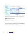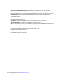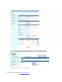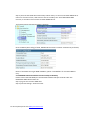
1
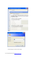
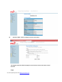
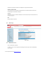
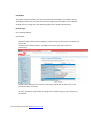
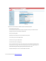
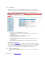
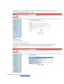
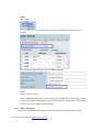
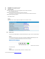
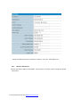
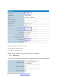
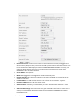
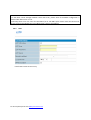
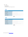
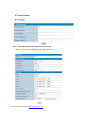
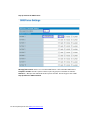
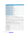
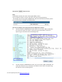
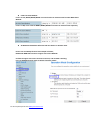
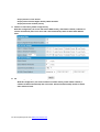
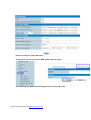
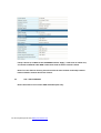
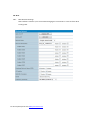
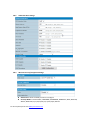
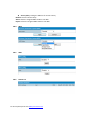
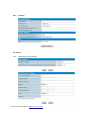
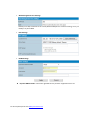
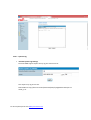
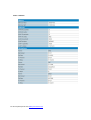
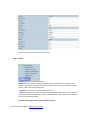
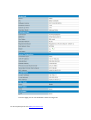
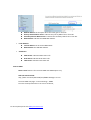
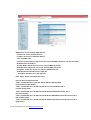
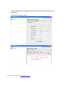
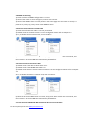
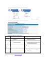
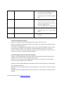
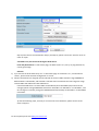
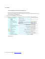
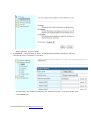
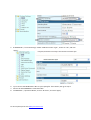
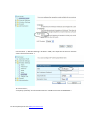
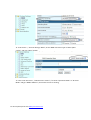
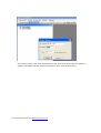
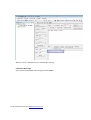
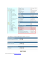
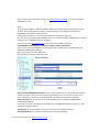
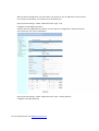
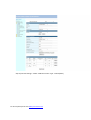
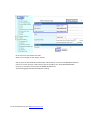
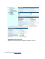
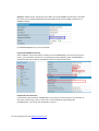
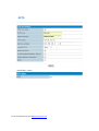
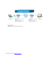
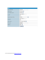
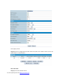
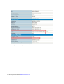
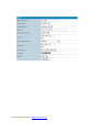
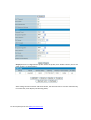
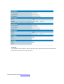
Proroute H685 3G and 4G Router User Manual Proroute.co.uk Proroute are a specialist provider of Cellular access equipment for Remote Internet connectivity and management of IT resources. The Proroute team are bringing a range of products to market to support professional installations where Broadband Wireless connectivity is essential to perform a particular function in industrial and domestic locations. This manual provides a detailed description of the functions and configuration parameters of the Proroute H685 3G and 4G to assist users in the implementation of the particular functions that may be required for bespoke installations. For more simple set up please follow the quick‐start guide provided with each product or download from www.proroute.co.uk. For all enquiries please visit www.proroute.co.uk Contents 1. Hardware Installation 1.1 1.2 1.3 1.4 1.5 1.6 1.7 1.8 Dimensions Connectors How to Install the unit SIM Card Terminal Block Grounding Power supply LED Functions 2. Overview 2.1 Logging onto the Router 2.2 Operation Mode ‐ How to configure Internet connectivity 2.2.1 WAN settings 2.2.2 WAN Cellular Network 2.2.3 Cell ICMP check 2.2.4 AP (Access point) Wi‐Fi Client 2.2.5 WAN – PPPoE (Xdsl 2.2.6 WAN Fixed IP 2.2.7 WAN DHCP (auto config) 2.3 LAN settings 2.3.1 Router IP Gateway IP 2.3.2 MAC binding 2.3.3 DNS Proxy 2.3.4 DHCP Client 2.3.5 Configuring Static Routing 2.4 VPN 2.4.1 IPSEC 2.4.2 PPTP 2.4.3 L2TP 2.4.4 Tunnel For all enquiries please visit www.proroute.co.uk 2.4.5 DTU Settings (Serial to Cellular Gateway Feature) 2.5 SMS/Voice Control 2.5.1 SMS 2.5.2 Voice 2.5.3 Alarm with SMS 2.6 Link Backup (Route Redundancy) 2.7 GPS – NOT STANDARD 2.8 Wi‐Fi 2.8.1 Basic Wireless Settings 2.8.2 Advanced Wi‐Fi settings 2.8.3 Wireless Security/Encryption Settings 2.8.4 WDS 2.8.5 WPS 2.8.6 Station List 2.8.7 Statistics 2.9 Firewall 2.9.1 MAC/IP/Port Filter Settings 2.9.2 Port Forwarding (Virtual Server Settings, NAT/NAPT) 2.9.3 DMZ Host 2.9.4 System Security 2.9.5 Content Filter Settings 2.10 Administration 2.10.1 Management 2.10.2 Router web port 2.10.3 Language, password and NTP settings 2.10.4 DDNS Settings 2.10.5 Firmware Upgrade 2.10.6 Settings Management 2.10.7 System Command 2.10.8 Systems Log 2.10.9 Statistics 2.10.10 Reboot For all enquiries please visit www.proroute.co.uk 2.10.11 Status 2.10.12 SNMP – Not standard 3. FAQ – Problem solving 3.1 Open Device Error 3.2 Read Error 3.3 Signal Strength has right number, but cannot dialup 3.4 Signal Strength shows 3.5 The router cannot be remote web visited 3.6 Signal shows 99 but still can connect to internet and get WAN IP 3.7 Router shows SIM card and network info, but cannot connect to internet 3.8 DDNS not working 3.9 Cannot Connect Router via RJ45 LAN 3.10 Cannot Connect H685 WiFi 3.11 Can Connect H685 WiFi via Manual IP but cannot via DHCP 3.12 Cannot get Cell WAN IP 3.13 Cannot power on 3.14 Sys log shows “connect script failed” 3.15 Proroute H685 is online, but cannot visit website. 3.16 Port forwarding not working 3.17 Serial DTU point‐to‐point solution not working 3.18 Can’t open device /dev/ttyUSBx. 3.19 PPTP is on, but cannot be through to PPTP Server 4. Test Samples 4.1 Two H685 make WiFi hotspot and WiFi client 4.2 GPS feature (For version with GPS feature only) 4.3 Port Forwarding (NAT, NAPT) test 4.4 Remote Web Login 4.5 WAN RJ45 Static (fixed IP) and Cellular Fail Over backup redundancy 4.6 WAN RJ45 DHCP and Cellular Fail Over backup redundancy 4.7 WAN RJ45 PPPoE and Cellular Fail Over backup redundancy 4.8 SMS Reboot/Cell UP/Cell Down control 4.9 LAN IP modification PPTP client connection 4.10 PPTP client connection 4.11 IPSec sample For all enquiries please visit www.proroute.co.uk 1. Hardware Installation This section describes the physical attributes of the Proroute H685. 1.1 Connectors For all enquiries please visit www.proroute.co.uk LAN: LAN RJ45 Ethernet port. WAN: WAN RJ45 Ethernet port. RST: sys reset button PWR: DC power socket. DC7~40V VCC: DC wire positive pole. DC7~40V GND: DC wire ground GND: Serial ground RX: serial receiving TX: serial transmission RST: reset router DIO0: digit I/O port 0 IDO1: digit I/O port 1 NC: no connection 1.2 Antenna connections. The PROROUTE UK/Euro version has 2 antenna connections for Cell and Wi‐Fi as follows: Feature Main Cellular Wi-Fi ANT1 ● ANT2 1.3 How to Install the unit For all enquiries please visit www.proroute.co.uk ANT3 ● ANT4 The Proroute H685 should be installed and configured correctly before putting the unit into service. The installation and configuration should be done by a trained and competent IT engineer. NOTE: DO NOT CONNECT/DISCONNECT THE POWER CABLE WHEN THE POWER IS SWITCHED ON AS THIS MAY DAMAGE THE UNIT 1.4 SIM Card The Proroute H685 has a removable panel on the reverse of the unit which is secured by 2 screws. To install the SIM remove the panel, insert the SIM card, which can only be placed one way, into to holder and push the holder down into position ensuring that it has properly made contact. If any force is needed then there is something wrong; recheck you have the SIM orientation correct. NOTE: NEVER INSERT THE SIM CARD WHEN THE POWER IS SWITCHED ON OR YOU MAY PERMANENTLY DAMAGE THE UNIT 1.5 Terminal Block The Proroute H685 has 2 options for connecting a power supply, via the mains power AC/DC adapter provided with the unit or via the designated pins on the connector provided. The connector can also be used to reset the unit or connect data: 14~24AWG is recommended. Please refer to the table 2‐4 for the interface definition of the power cable and connection sequence. It is recommended that the connections to the connector block be made when the block is removed from the unit to prevent providing intermittent power to the unit during install. When all wires are secured the connector can be placed into position Notes: The cables’ insulating striping length is approx. 7mm. For all enquiries please visit www.proroute.co.uk Attention: 1. The power cable should be connected correctly. Please double check before the unit is switched on as incorrect connections may destroy the equipment. 2. Power terminals: Pin 1 and Pin 2; 3. Here:Pin 2 is “GND”, PIN 1 is power input “Vin”(DC7~30V) PIN 1 2 3 4 5 Signal VCC GND TX RX PGND Description +7‐30V DC Input Ground Transmit Data Receive Data Ground 6 RST Reset 7 8 9 DIO0 DIO1 NC General Purpose I/O General Purpose I/O No connection For all enquiries please visit www.proroute.co.uk Note Current:12V/1A The Reset Pin has the same Function as the reset Button on the base of the unit. To activate, make a short connection to GND as follows: 1 sec low level will reboot. 3 seconds, the device will restore factory settings. Not standard Not standard I/O Terminal on router Port 3 (GND) Port 4 (RX) Port 5 (TX) DB9 Serial port (RS485 or RS232) Pin 5 Pin 3 Pin 2 Notes: RS232 functionality is not present on the standard unit. 1.6 Grounding To ensure a safe, stable and reliable operation the Router must be grounded properly. 1.7 Power supply Proroute H685 is designed to operate in complex environments where the power range can be very large. To improve the stability of the system, Proroute incorporates advanced power management technology. However, the DC power supply still needs careful attention and clear understanding as to the behaviour of the supply. Once the levels have been established and tested it is always best to keep them in this tested range for device stability. Proroute input power supply is +7~+ 30V, the standard configuration is 12V/1A. 1.8 LED Functions After the Antenna and Power are connected insert a valid SIM card and power on the Protoute series following the instructions provided previously. During the start‐up sequence the SYS LED will blink for a few seconds, this indicates the system start‐up is normal; following this if the CELL LED flashes and then remains on constantly this indicates the network is online; if the VPN light is on constantly, this indicates the VPN tunnel has been set up. The table below summarises the LED indication lights. For all enquiries please visit www.proroute.co.uk LED SYS Indication Light On for 25 seconds blink Off or still on after 25 seconds blink Description On for 25 seconds after power supply Off Ethernet connection abnormal On Ethernet is connected CELL On Off On VPN tunnel set-up VPN tunnel set-up failure or not activated Access to the Internet OK WIFI On Enable LAN VPN System set-up normally System set-up failure Data transmission in Ethernet For all enquiries please visit www.proroute.co.uk WAN Signal Off Disable blink Data transmission on WAN Off WAN connection abnormal or not active On WAN is connected Off No signal, or signal checking is not ready 4s blink 1 time Signal bar is 1 3s blink 1 time Signal bar is 2 2s blink 1 time Signal bar is 3 1s blink 1 time Signal bar is 4 1s blink 2 times Signal bar is 5 2. Overview The Proroute H685 has a built in Web Configuration Interface, including management and debugging tools. The following sections describe the necessary features and settings to configure your router. 2.1 Logging onto the Router To log on to the H685 launch your browser and type in the default IP address: 192.168.8.1. This address can also be found on the label on the reverse of the unit adjacent to the SIM card location. The most straight forward method of connecting your PC to the Router is via DHCP (Dynamic Host Control Protocol) and select ‘obtain an IP address automatically’ and ‘obtain a DNS connection automatically’ as the menu/diagram below shows: For all enquiries please visit www.proroute.co.uk Successful login will reveal the status page: For all enquiries please visit www.proroute.co.uk 2.2 Operation Mode ‐ How to configure Internet connectivity The diagram shows the default settings for normal internet access and remote control functions Bridge For all enquiries please visit www.proroute.co.uk All Ethernet and wireless interfaces are bridged into a single interface/network Gateway – default setting The first Ethernet port is treated as the WAN interface. The LAN and wireless interface are bridged together and treated as LAN ports AP Client The wireless interface is treated as a WAN port. The other Ethernet ports and the Wi‐Fi AP are treated as LAN ports NAT Network Address translation 2.2.1 WAN settings 2.2.2 WAN Cellular Network This is ‘Cell Network’ by default. In addition to this It can also support the following connection types: static IP, DHCP,PPPoE, L2TP and PPTP For all enquiries please visit www.proroute.co.uk Cell Modem The Cellular modem installed in the unit will support ETSI based HSPA+ or DC‐HSPA+ and LTE depending on which unit you have purchased. This will generally be Huawei or Sierra Wireless although this may change over time depending upon further product developments. Network Type Set to AUTO by default. Online Mode ‐ Keep Alive: Means always online. Regardless of there being any data present the Router will stay on line ‐ On Demand: The Router will dial – up /Make a connection when there is data for transmission ‐ The Idle time in Minutes is the time the router will go offline after no data is sent. In the case shown above, 5 minutes. On Time: The Router will go offline according to the schedule it is given. Up to 4 times can be selected. For all enquiries please visit www.proroute.co.uk ‐MAC Clone. Can be enabled or disabled if required. Disabled by default. ‐ Advanced Parameter Groups Click advanced Parameter Groups and this will expand to allow you to define the APN settings to connect to your Network and SIM card. Dial Up: UK setting *99# APN (Access Point Name): Given by your SIM service provider User: Given by your service SIM provider Password: Given by your SIM provider Command: Not used. For Debug only. Auth. Type (Authentication Type) Three options (Auto, PAP, CHAP/MS‐CHAP/MS‐CHAP2). Generally if you are using a normal internet SIM only then Auto is the right selection. If a Fixed IP SIM is being used then generally CHAP authentication is used. PIN code: Generally not in use or recommended. Leave blank. For all enquiries please visit www.proroute.co.uk When the APN settings, User and Password and other settings have been changed DO NOT FORGET to select Add/Edit. Advanced Cell Options If these are not known please leave all of these as default settings as per the following: For all enquiries please visit www.proroute.co.uk 2.2.3 Cell ICMP check This section refers to Internet Control Message Protocol or better known as the PING Reboot facility and allows the Router to maintain its connection with the network regardless of traffic status or prevailing network conditions. This is perhaps one of the most useful supportive functions to ensure that remote devices stay connected. Active: tick to enable ICMP/PING Reboot check feature Check method: fill in the checking domain name or IP. Click HOST/IP check button to verify before using it. Check interval time (sec): set the interval time of every check Check Count: set the checking count number Reboot Count Before Sleep: H685 Proroute stop checking after it has failed for set number of times. Sleep Time (min): Proroute H685 will sleep for det period before resuming check. Example shown in picture above: Proroute will check “www.google.com” and “8.8.8.8”, it will check 3 times. After the first check, it will repeate after 60 seconds. In total it will check 3 times. If all 3 times fail, Proroute H685 will reboot. If it reboots 3 times continuously, Proroute H685 goes to sleep and stops checking. The sleep time is 5 minutes. After 5 minutes, Proroute H685 resumes the checking cycle. 2.2.4 AP (Access point) Wi‐Fi Client Set PROROUTE as an AP client, PROROUTE will connect the upper WiFi router or WiFi AP. Step1) For all enquiries please visit www.proroute.co.uk PROROUTE web ‐‐ Operation Mode – Choose “AP Client”, and click apply button. Wait some time until the PROROUTE applies the settings. Step2) WIFI – AP Client Fill in the parameters. SSID: input the WiFi router’s SSID Security Mode: choose the correct one to match to the WiFi router/AP you want to connect. Encryption Type: choose the correct one to match to the WiFi router/AP you want to connect. For all enquiries please visit www.proroute.co.uk Step3) WIFI ‐‐ Basic Select the correct channel matched to the serving/upper WiFi Router/AP you want to connect. Then choose the same Channel in Proroute H685 as follows, Step4) Internet Settings – WAN At the “WAN Connection Type”, choose “DHCP (Auto Config)”, and click the “Apply” button. The Proroute H685 will automatically connect the WiFi Router and get local IP from the Wi‐ Fi router. This can checked at status info page. 2.2.5 WAN – PPPoE (Xdsl Set the Proroute H685 WAN to PPPoE, Proroute will connect to the upper PPPoE modem. For all enquiries please visit www.proroute.co.uk Step 1) Connect the RJ45 cable between PPPoE modem to PROROUTE WAN RJ45 port. Once connected, the PROROUTE Web Ethernet Port Status will display. Notes: you may not see the WAN RJ45 connection status. But it will flash to fresh the status every 30 seconds. Step 2) PROROUTE web – Operation Mode, choose “Gateway” mode Step 3) PROROUTE web – Internet Settings – WAN – WAN Connection Type, choose “PPPoE (ADSL)” WAN Connection Type: choose “PPPoE (ADSL)” For all enquiries please visit www.proroute.co.uk User Name: fill in the PPPoE username Password: fill in the PPPoE password Operation Mode: Keep Alive: PPPoE will remain online regardless if there is data transmission. Fill in the Redial Period time. On Demand: PPPoE dialup with data transmission on demand. Set the Idle Time. PPPoE will be offline if the set idle time has no data transmission. Manual: Manually dialup required. Click “Apply” button. Step 4) PROROUTE web – Status, it display the WAN IP once the PPPoE is online. 2.2.6 WAN Fixed IP Set the Proroute H685 WAN via a STATIC fixed IP fed by the upper router via STATIC fixed IP. Step 1) Connect RJ45 cable between Upper Router LAN RJ45 to PROROUTE WAN RJ45 port. Once it’s connected, the PROROUTE Web Ethernet Port Status will display. Notes: you may not see the WAN RJ45 connection status. But it will flash to fresh the status every 30 seconds. Step 2) PROROUTE web – Operation Mode, choose the “Gateway” mode For all enquiries please visit www.proroute.co.uk Step 3) PROROUTE web – Internet Settings – WAN – WAN Connection Type, choose “STATIC (fixed IP)” WAN Connection Type: choose “STATIC (fixed IP)” IP Address: fill in one IP Address. This IP Address should be same range of the Upper Router. For example, the Upper Router LAN IP is 192.168.1.1 and Subnet Mask is 255.255.255.0, you can fill in the parameters as above. Subnet Mask: fill in the Subnet Mask from the Upper Router. Default Gateway: fill in the Upper Router’s Gateway IP. Primary DNS Server: If your Upper Router supports DNS proxy, fill in the Upper Router’s LAN IP as Primary DNS Server. Or you can fill in the correct DNS Server IP. Secondary DNS Server: Fill in a working secondary DNS Server IP. Click the “Apply” button. Step 4) PROROUTE web – Status, it display the WAN IP once the STATIC (fixed IP) is online. For all enquiries please visit www.proroute.co.uk 2.2.7 WAN DHCP (auto configuration) Set PROROUTE WAN via DHCP (Auto config), the PROROUTE will connect to the upper router via DHCP. Step 1) Connect RJ45 cable between Upper Router LAN RJ45 to PROROUTE WAN RJ45 port. Once it’s connected, the PROROUTE Web Ethernet Port Status will display. Notes: you may not see the WAN RJ45 connection status. But it will flash to refresh the status every 30 seconds. Step 2) PROROUTE web – Operation Mode, choose “Gateway” mode Step 3) PROROUTE web – Internet Settings – WAN – WAN Connection Type, choose “DHCP (Auto config)” For all enquiries please visit www.proroute.co.uk WAN Connection Type: choose “DHCP (Auto config)” Click “Apply” button. Step 4) PROROUTE web – Status, it display the WAN IP once the DHCP (Auto config) is online. 2.3 LAN settings For all enquiries please visit www.proroute.co.uk Setting the LAN parameters, include the IP address, sub mask, VLAN, DHCP, etc. 2.3.1 Router IP Gateway IP Default, the Router LAN IP is 192.168.8.1. If users want to modify it, please change the related parameters. For all enquiries please visit www.proroute.co.uk IP Address: change to the value you need Start IP Address: for DHCP start IP End IP Address: for DHCP end IP Default Gateway: manually change it after you modify the IP Address. 2.3.2 MAC binding Proroute supports 3 groups of MAC Binding. The parameter value format is shown below: For all enquiries please visit www.proroute.co.uk 2.3.3 DNS Proxy Proroute’s default enables DNS Proxy. With this, the Proroute H685 can get obtain DNS info automatically and assign it to the PC/Device. If this is disabled, please input the correct DNS info for your PC/Device, otherwise, it may not work correctly. 2.3.4 DHCP Client Lists the Clients which gain IP address from DHCP. 2.3.5 Configuring Static Routing This section introduces the Routing Table and how to configure static router functions. Routing Table This page shows the key routing table of this router. New Static Router This page is about how to set the static routing function of the router. For all enquiries please visit www.proroute.co.uk Destination: please enter the Target Host or IP network segment Range: Host or Network can be selected Gateway: IP address of the next router. Interface: You can select the corresponding interface type. Comment: helpful mnemonics. Notice: The Gateway and LAN IP of the router must belong to the same network segment. If the destination IP address is not the same as the host, and then the Subnet Mask must be 255.255.255.255. If the destination IP address is an IP network segment, it must match with the Subnet Mask. For example, if the destination IP is 10.0.0.0, and the Subnet Mask is 255.0.0.0. 2.4 VPN 2.4.1 IPSEC For all enquiries please visit www.proroute.co.uk IPsec connect name: make sure the name in client and server are same, we suggest to use domain name (111.vpn1.com). if you want to build a point‐to‐point channel, the IPsec name have to be written as DEV+equipment ID+name (DEV281250D52F2A1452.vpn1.com), and make sure both the client and server are inputing Client equipment ID. You can find PROROUTE’s ID in the Status interface. Service Mode: Server/Client Mode: Main/Aggressive. The Aggressive mode is commonly used. Remote Gateway: This choice just appears in the Client mode and it is used to fill the IP address in the Server. Local IP address: Fill LAN IP of this device. You can fill an IP or a network segment. Remote IP address: Fill the IP of the other router. Authentication: Commonly, Pre‐Shared Key is chosen. And the Client and Server must choose the same key. Advanced AKE settings: There are some encryption methods in this field. You must use the settings in this field when VPN tunnel needs to be built between PROROUTE and other brand VPN server. For all enquiries please visit www.proroute.co.uk Example: Connected cisco 7200 and PROROUTE How to config PROROUTE as VPN clinet IPsec Name: make sure the name in client and server are same, we suggest to use domain name(111.vpn1.com). if you want to build a point‐to‐point channel, the IPsec name have to be written as DEV+equipment ID+name(DEV281250D52F2A1452.vpn1.com), and make sure both the client and server are inputing Client equipment ID. You can find PROROUTE’s ID in the Status interface. How to config CISCO 7200 as VPN Server For all enquiries please visit www.proroute.co.uk crypto keyring jordan pre‐shared‐key hostname jordan key test crypto isakmp profile jordan description china SZ shenzhen keyring jordan match identity host jordan keepalive 60 retry 10 crypto ipsec transform‐set vpnset esp‐des esp‐sha‐hmac crypto ipsec profile jordan set transform‐set vpnset set isakmp‐profile jordan crypto dynamic‐map jordan 1 set security‐association lifetime kilobytes 536870912 set security‐association lifetime seconds 43200 set transform‐set vpnset set isakmp‐profile jordan reverse‐route crypto map COREVPN 26 ipsec‐isakmp dynamic jordan For all enquiries please visit www.proroute.co.uk 2.4.2 PPTP PPTP feature works as Client only. PPTP VPN Active: tick it to enable VPN feature. PPTP User: fill in the username from the PPTP Server. PPTP Password: fill in the password from the PPTP Server. PPTP Server: fill in the PPTP Server which is IP address or domain name. Remote Lan/Mask: fill in the PPTP Server’s LAN range and submask. Local PPTP IP: default chooses “dhcp”. If you choose “static”, please fill in a local PPTP assigned IP, which depends on PPTP Server’s settings. MPPE Encryption: selection depends on PPTP Server’s settings. 40 bit Encryption(Default is 128 bit): selection depends on PPTP Server’s settings. Refuse Stateless Encryption: selection depends on PPTP Server’s settings. MPPC: Selection depends on PPTP Server’s settings. Click “apply” button to activate the settings. The PPTP client will try to connect the PPTP Server automatically. For all enquiries please visit www.proroute.co.uk Notes: 1) If the PPTP cannot through between client and server, please check if the MPPE configuration is matched with PPTP server or not. 2) Normally PPTP server has route for 192.168.1.1/24 or 192.168.0.1/24. Please check the PPTP server has the route of 192.168.8.0/24 if your H820 router is with IP 192.168.8.1 2.4.3 L2TP L2TP feature works as Client only. For all enquiries please visit www.proroute.co.uk 2.4.4 Tunnel Tunnel Feature The PROROUTE Tunnel feature supports two GRE. For all enquiries please visit www.proroute.co.uk IP Tunnel Feature 2.4.5 DTU Settings (Serial to Cellular Gateway Feature) Notes: this feature is for PROROUTE with DTU option only. For all enquiries please visit www.proroute.co.uk DTU status: open and close DTU DTU Serial setting serial baudrate: support 300/1200/2400/4800/9600/19200/38400/57600/115200bps serial parity: support none/odd/even serial databits: support 7 bits and 8 bits serial stopbit: support 1 bits and 2 bits serial flow control: support hardware/software DTU config mode: can configure as client or server. Protocol: support TCP/UDP server 1~server 4: fill in the centre server IP or Domain name and port. If you configure one server, the data will transfer to this server. If you configure one more servers, the data will transfer to all the servers at the same time. Send heart beat: open or close heart beat. heart beat interval time: set interval time to send each heart beat heart beat information: define the content of heart beat send delay time: waiting time to send data. Add id string to head: add an ID string in the data or heartbeat. 2.5 SMS/Voice Control 2.5.1 SMS Step 1) click “SMS/Voice” For all enquiries please visit www.proroute.co.uk Step 2) Activate the SMS feature Message/Voice status: select “on” to enable SMS feature. “off” to disable SMS feature. Telephone number: Sender’s phone number input. 10 groups are available to allocate. Number 1….10: input the dedicated sender’s phone number. Do not forget to Tick “SMS” Step 3) Define the SMS command For all enquiries please visit www.proroute.co.uk SMS Command: select “on” to enable it. “off” to disable it. Send ack SMS: If select “on”, the router will send command feedback to sender’s phone number. If select “off”, the router will not send command feedback to sender’s phone number. Reboot Router Command: input the command for “reboot” operation, default is “reboot”. Get Cell Status Command: input the command for “router cell status checking” operation, default is “cellstatus”. For example, if we send “cellstatus” to router, router will feedback the status to sender such as “Router SN: 086412090002 cell_link_up”, which indicated the router SN number and Cell Working Status. Cell link‐up Command: input the command for “router cell link up” operation, default is “cellup”. If router gets this command, the Router Cell will be online. Cell link‐down Command: input the command for “router cell link down” operation, default is “celldown”. If router gets this command, the Router Cell will be offline. DIO_0 Set Command: input the command for I/O port 0. For SMS feature, please keep the parameter default. DIO_0 Reset Command: input the command for I/O port 0. For SMS feature, please keep the parameter default. DIO_1 Set Command: input the command for I/O port 1. For SMS feature, please keep the parameter default. DIO_1 Reset Command: input the command for I/O port 1. For SMS feature, please keep the parameter default. DIO Status Command: input the command for I/O port status. For SMS feature, please keep the parameter default. For all enquiries please visit www.proroute.co.uk Step 4) Click button to save Note: 1) SIM Card inserted in the router must support SMS or Voice. 2) Try to add zone code or country code if the command cannot get working. For example, we set the number 13798257916, and if the command cannot work, please try to put the country code 86 as followed picture. Here set an example, we set the parameters for SMS/Voice as above. 1) Use the cell phone 13798257916 to send “down” to the router’s SIM Card Number, the router will receive the “down” command, and it will be off‐line. And in the System Log, we shall find a info as following marks. 2) Use the cell phone 13798257916 to send “up” to the router’s SIM Card Number, the router will receive the “up” command, and it will be online. And in the System Log, we shall find a info as following marks. For all enquiries please visit www.proroute.co.uk 2.5.2 Voice This feature enables the Router to send SMS to pre‐defined phone numbers for warnings and alarms. Step 1) enable Alarm feature Step 2) set the dedicated phone numbers for SMS Alarm For all enquiries please visit www.proroute.co.uk Step 3) Configure the voice command Normal signal count for check again: prevents repeating of alarms. With the setting above, the Proroute H685 checks the signal every 20s, if it sees the signal quality of Zero 10 times, Proroute H685 will send an Alarm via SMS. After the alarm, this feature will be locked, but Proroute H685 keeps checking signal quality every 20s, following this occurrence if the signal quality is measures better than Zero for 8 attempts then the alarm feature will be unlocked; then the alarm feature resumes normal operation. For all enquiries please visit www.proroute.co.uk 2.6 Link Backup (Route Redundancy) Operation Mode Active: disable or enable the link redundancy Back to Higher Primary When Possible: If you tick this option, the Proroute H685 will work on the backup link, whether it fails or not, it will return to main link if main link is available again. If you do not tick this option, the Proroute H685 will not switch back to main link when the current link fails. Link Priority Settings WAN1: Cellular Wireless WAN2: WiFi DHCP Wireless WAN3: Wired XXX (XXX=DHCP, STATIC, PPPOE) OFF: Check OFF Blank to disable or uncheck to enable the link redundancy Priority: High Priority, Middle Priority, Low Priority. Link Check Settings Check Count: for example, set it as 3. Router check link live 3 times. Check Interval Time(min): for example, set is as 2. Router check link live every 2 minutes. For all enquiries please visit www.proroute.co.uk Used The Same Method: If set it as YES, WAN1/WAN2/WAN3 use same check IP or domain name from ALL WAN Check Method. If set is as NO, users need set WAN1/WAN2/WAN3 live check IP or domain name separately. All WAN Check Method: define the link live check IP or domain name. How to use Link Backup feature? An example as follows, PROROUTE WAN RJ45 connects to upper side router LAN RJ45. Confirm the upper side router connects to internet, and its DHCP is working. First, Set PROROUTE work mode as default “Gateway mode”. For all enquiries please visit www.proroute.co.uk Step 1) activate it. Tick “Active” Step 2) click at “Back To Higher Primary When Possible” Step 3) Choose the network priority. A. Cellular as Low Priority, DHCP as High Priority With this configuration, the router will work at DHCP mainly, and if DHCP is failed, it switches to cellular automatically after some time. And it will automatically switch to DHCP when DHCP is fixed. B. Cellular as High Priority, DHCP as Low Priority With this configuration, the router will work at cellular mainly, and if cellular is failed, it switches to DHCP automatically after some time. And it will automatically switch to cellular when cellular is fixed. For all enquiries please visit www.proroute.co.uk DHCP: An example of a DHCP WiFi Client. Step 4) if Step 3 choose A, please set WAN as DHCP and click “Apply” The PROROUTE gets WAN IP and default gateway from the up‐side router. For all enquiries please visit www.proroute.co.uk If Step 3 choose B, set WAN as CELL NETWORK and click “Apply”, it will work on cellular first, and switch to LAN RJ45 cable WAN or WiFi client mode if cellular network is failed. Notes: for route fail over feature, please first make the main network and backup network both work before activate the fail over feature. 2.7 GPS – NOT STANDARD Notes: GPS feature is for Proroute H685 with GPS option only. For all enquiries please visit www.proroute.co.uk WAN Connection Type GPS Active: please click it once you need use the GPS feature. GPS Send to: Choose “Serial” or “TCP/IP” method. The router only receives the GPS signal, it will not process it. It will just send the received GPS signal to your GPS processor. If the GPS processor is connected to the 3G Router via Serial Port, then please choose “Serial”. If choose “TCP/IP” method, please configure the GPS to NET Settings. If choose “Serial” method, please configure the GPS to Serial Settings. GPS to NET Settings Sock type: tcp or udp Server: fill in the correct destination server IP or domain name Server port: fill in the correct destination server port For all enquiries please visit www.proroute.co.uk GPS to Serial Settings serial baud rate: 9600/19200/38400/57600/115200bps for choice serial parity: none/odd/even for choice serial data bits: 7/8 for choice serial stop bits: 1/2 for choice serial flow control: none/hardware/software for choice For all enquiries please visit www.proroute.co.uk 2.8 Wi‐Fi 2.8.1 Basic Wireless Settings. Note: Default is Channel 1, we recommend changing this to Channel 11 in the UK if the Wi‐Fi is being used. For all enquiries please visit www.proroute.co.uk Wireless Network Radio On/Off: If it indicates RADIO OFF, it means the radio is on. You can click RADIO OFF to disable it. If it indicates RADIO ON, it means the radio is off. You can click RADIO ON to enable it. In Summary – This is a COMMAND not a STATUS. WiFi On/Off: If it indicates WiFi OFF, it means the radio is on. You can click WiFi OFF to disable it. If it indicates WiFi ON, it means the radio is off. You can click WiFi ON to enable it If WiFi is ON, the WiFi LED will be light on. If WiFi is OFF, the WiFi LED will be off. . In Summary – This is a COMMAND not a STATUS. Network Mode: 802.11b/g/n mode selection Network Name(SSID): Input the SSID, Hidden & Isolated for option. If tick Hidden, the WiFi SSID will not broadcast. Multiple SSID1: Proroute H685 supports multiple SSID 8 groups totally. Broadcast Network Name (SSID): Enable or Disable SSID broadcast. BSSID: indicates the MAC of WiFi Frequency (Channel): current working frequency and channel. For all enquiries please visit www.proroute.co.uk 2.8.2 Advanced Wi‐Fi settings 2.8.3 Wireless Security/Encryption Settings SSID choice: select the SSID you want to configure Security Mode: include Disable, OPENWEB, SHAREDWEB, WEBAUTO, WPA, WPA‐PSK, WPA2, WPA2‐PSK, wpa‐psk/wpa2‐psk, wpa1/wpa2, 802.1X. For all enquiries please visit www.proroute.co.uk Access policy: setting the MAC list for access or deny. Disable: close the Access Policy. Allow: allow the assigned MAC enable to use WiFi Reject: refuse the assigned MAC enable to use WiFi 2.8.4 WDS 2.8.5 WPS 2.8.6 Station List For all enquiries please visit www.proroute.co.uk 2.8.7 Statistics 2.9 Firewall 2.9.1 MAC/IP/Port Filter Settings For all enquiries please visit www.proroute.co.uk 2.9.2 This section is mainly about MAC/IP/Port filter settings Basic Settings MAC/IP/Port Filtering: Disable or Enable Default Policy ‐‐ The packet that don't match with any rules would be: Dropped/Accepted MAC/IP/Port Filter Settings Source MAC address: Fill the MAC address which needs to filter. Dest IP Address: IP of the target destination computer( the computer which the data packet will be sent to) Destination Port Range: port range of target computer Source Port Range: port range of the computer which sends data Action: choose Accept or Drop Comment: input comment here Current MAC/IP/Port filtering rules in system The configured rules are displayed in this table. Port Forwarding (Virtual Server Settings, NAT/NAPT) – Also see Quick start guide for practical examples. For all enquiries please visit www.proroute.co.uk Port forwarding is the process used by your router or firewall to deliver the right network data to the right port. Computers and routers use ports as a way to organise network data. Different types of data, such as web sites, file downloads, and online games, are each assigned a port number. By using port forwarding, the router or firewall sends the correct data to the correct place. Virtual Server Settings: open and close Settings. IP address: fill the IP address of forwarding. The first blank is for local IP address, the second blank is for port. Port Range: fill the Port of forwarding. For all enquiries please visit www.proroute.co.uk 2.9.3 DMZ Host In computer networking, DMZ is a firewall configuration for securing local area networks LANs. DMZ Settings: opens and closes the DMZ feature. Disable: close DMZ feature Enable: enable the DMZ feature for assigned IP Enable Super DMZ: enable the DMZ feature for assigned MAC DMZ IP Address: Please Enter the IP address of the computer which you want to set as DMZ host DMZ MAC Address: Please Enter the MAC address of the computer which you want to set as DMZ host Except TCP port: disable or enable for TCP port Note: When DMZ host is settled, the computer is completely exposed to the external network; the firewall will not influence this host. For all enquiries please visit www.proroute.co.uk 2.9.4 System Security Includes Remote management, Ping from WAN Filter, Block Port Scan, Block SYN Flood and SPI Firewall (Stateful Packet Inspection). 2.9.5 Content Filter Settings You can setup Content Filters to restrict content access, this can include Webs Content Settings, URL filters and Host Filters. Proxy/Java/Activex Filter For all enquiries please visit www.proroute.co.uk Support Proxy, Java, ActiveX filter. Web URL Filter Fill in the URL for filter. Web Host Filter For all enquiries please visit www.proroute.co.uk 2.10 Administration 2.10.1 Management Language Settings Select Web display language. Default is English. Can OEM other languages. Administrator Settings Select Web display language. Default is English. Can OEM other languages. WatchDog For all enquiries please visit www.proroute.co.uk Web Management Port Settings Default port is 80, sometimes if the carrier/ISP block 80 port for remote incoming, can try to modify it to port 10000. NTP Settings DDNS Settings Dynamic DNS Provider: choose the right DNS server provider. Supported server list. For all enquiries please visit www.proroute.co.uk Account: fill in account info. Password: fill in password info. DDNS: fill in DDNS info. 2.10.2 Router web port Please input the web port of the router. Normally we use 80 or 10000. Please re‐power the router after changing the port number. 2.10.3 Language, password and NTP settings For all enquiries please visit www.proroute.co.uk Select Language Administrator Settings. The default both are admin. NTP Settings 2.10.4 Firmware Upgrade Upgrade the firmware to obtain latest functionality when available or if needed to activate new feautures. It takes about 2~5 minutes. Choose the correct firmware file, then click “Apply” button. Notes: Highly recommend to “Load Default” to the Proroute H685 after uploading the firmware. “Load Default” will cause all settings to be lost. Please backup/export the settings before “Load Default”. Or re‐configure the PROROUTE after “Load Default” For all enquiries please visit www.proroute.co.uk 2.10.5 Settings Management You can make a backup of current settings or restore the previous settings of the router . Export settings: click ‘export’ to export configuration files and then select save path. Import settings: click ‘browse’, select previous backup configuration files and then click ‘Import’. Then all the previous settings will be recovered. Load Factory Defaults: click ‘Load Default’ then all settings will be restored to factory settings. This is only to be used if all other options have not worked. 2.10.6 System Command Input the related command at command area. Click “Apply” button to execute. Then click “Refresh” button. The blank area will display the result. For all enquiries please visit www.proroute.co.uk 2.10.7 Systems Log Remote System Log Settings Proroute H685 support export the sys log into remote server. This requires sys log server tool. Download link: http://www. Proroute/download/tool/SyslogWatcherSetup‐4.2.0‐ win32_1.rar For all enquiries please visit www.proroute.co.uk Local System Log For all enquiries please visit www.proroute.co.uk 2.10.8 Statistics For all enquiries please visit www.proroute.co.uk Display the statistics information of system flow 2.10.9 Reboot Question: Why to use Reboot Feature? Answer: Router is similar a computer, whose performance depends on hardware and software. The Router’s performance becomes weaker after very long time working. With reboot, it will refresh the performance. Question: Is necessary to use the Reboot Feature? Answer: Not really. Our router has high reliable and stable performance. It not requires using reboot feature compulsively. However, Reboot Feature will double ensure the router to be more stable and reliable. Proroute H685 supports three types of Reboot Feature. For all enquiries please visit www.proroute.co.uk Reboot AT Time Settings Users can define the exact time to reboot for every day. Reboot AT Time Settings Users can set timer to reboot. Reboot AT Time Settings Manually click “Reboot” button to reboot immediately 2.10.10 Status For all enquiries please visit www.proroute.co.uk From this page you can see the Router’s basic running state. For all enquiries please visit www.proroute.co.uk Ethernet Port Status System Info Product Model: indicates the model name SN: indicates the product SN Software Version: software version reveals the status of software update. Hardware Version: indicates the hardware version System Up Time: this time directly reveals router working hours Operation Mode: indicates the router working mode Cell Network Info Cell Modem: indicates inside cellular module modem name IMEI/ESN: indicates IMEI or ESN info of inside cellular module modem Sim Status: indicates sim card status Selected Network: indicates the selected working network Registered Network: indicates the current working network carrier ID Sub Network Type: indicates the current working network type Signal: indicates the current network state of 2G/3G. 0 and 99 mean no signal. Cell state: indicates the cellular is online or offline Internet Configurations Connected Type: indicates the selected WAN type. For all enquiries please visit www.proroute.co.uk WPN IP address: the IP expose when the router gets on internet. Primary Domain Name Server: indicates the primary DNS of set or from ISP. Secondary Domain Name Server: indicates the secondary DNS of set or from ISP. MAC Address: indicates the WAN MAC address Local Network Local IP address: the Proroute H685 LAN IP MAC Address: the LAN MAC address VPN Status IPSEC Status: indicates IPSEC status info PPTP Status: indicates PPTP status info L2TP Status: indicates L2TP status info 2.10.11 SNMP Notes: SNMP feature is for Proroute H685 with SNMP option only. Soft tool download link: http://www. Proroute/download/tool/SNMP‐JManager‐v1.0.rar Proroute H685 web page – Internet Settings – SNMP Fill in the related parameters in the screen as follows, For all enquiries please visit www.proroute.co.uk SNMP Active: tick it to active SNMP feature. Contact Info: set the contact info here Location: set router’s installation address. User: set public name Host/Lan: set the network range to visit the router via SNMP, default we set all as 0.0.0.0./0 Writable: tick it to enable it. Security Mode: choose the correct one, only for SNMP V3 version. Authentication: choose the correct one, only for SNMP V3 version. Encryption: choose the correct one, only for SNMP V3 version. Authentication Password: fill in the right one. Encryption Password: fill in the right one. Click “Apply” button and reboot the router. Here list the most important OID: 1.3.6.1.4.1.2021.255.4.1.2.9.103.101.116.95.109.111.100.101.109.1 (read module modem model) 1.3.6.1.4.1.2021.255.4.1.2.10.103.101.116.95.117.112.116.105.109.101.1 (system running time) 1.3.6.1.4.1.2021.255.4.1.2.12.103.101.116.95.109.101.109.95.102.114.101.101.1 (memory capacity) 1.3.6.1.4.1.2021.255.4.1.2.15.103.101.116.95.99.101.108.108.95.115.116.97.116.117.115.1 (3G network status) 1.3.6.1.4.1.2021.255.4.1.2.15.103.101.116.95.108.50.116.112.95.115.116.97.116.117.115.1 (pptp status) For all enquiries please visit www.proroute.co.uk 1.3.6.1.4.1.2021.255.4.1.2.15.103.101.116.95.112.112.116.112.95.115.116.97.116.117.115.1 (l2tp status) List client side’s picture as follows, For all enquiries please visit www.proroute.co.uk 3. FAQ – Problem solving 3.1 Open Device Error With this error, most of time the module inside the router is loosen. Please try to fasten it. 3.2 Read Error With this error, it indicates the sim card is not well touched with sim card slot. Try to check the sim card is right put. Try to scrap the sim card slot and make it clean. 3.3 Signal Strength has right number, but cannot dialup Try to check the WAN port setting is correct. 3.4 Signal Strength shows 99 Here it shows 16, it means signal is okay. If shows 99, try to check the sim card is has enough balance. Or if the data business is supported. 3.5 The router cannot be remote web visited 1) Default the router’s web port is 80. Some network ISP block the 80 of incoming. So confirm with your ISP which port can be visited. Or you can change other port to try, such as port 10000. Refer to chapter 3.3.14.1.1 Router web port to operate. 2) Check if the router’s WAN IP can be ping through via the PC. 3.6 Signal shows 99 but still can connect to internet and get WAN IP Our router built‐in different types of modem inside, some modem cost this. But will not affect the use. 3.7 Router shows sim card and network info, but cannot connect to internet Check the sim card is with balance or limited service by the ISP. For all enquiries please visit www.proroute.co.uk 3.8 DDNS not working 1) Please confirm the DDNS configuration is correct. 2) Check if the router is online and get IP, and can visit internet. 3) Check if the WAN IP from sim card (shows in the status page once the router is online) is a public IP or privacy IP, privacy IP will make DDNS no work. 3.9 Cannot Connect Router via RJ45 LAN 1) Please check if Ethernet cable is correctly connected. 2) Double check PC network card IP is correct configured. Please refer to Chapter 3.2 3) Try to disable the PC network card, and re‐enable it. 4) Reset the Proroute H685. Power on router, keep press “RST” button until 12 seconds, and then release it. Proroute H685 will automatically load default. 3.10 Cannot Connect Proroute’s WiFi 1) Double check if the device’s WiFi switch is on. 2) Double check if the PROROUTE’s WiFi is on. 3) Double check Device’s wireless network card IP is correct configured. Please refer to Chapter 3.2 4) Try to disable the Device’s network card, and re‐enable it. 5) Reset the Proroute H685. Power on router, keep press “RST” button until 12 seconds, and then release it. Proroute H685 will automatically load default. 3.11 Can Connect PROROUTE WiFi via Manual IP but cannot via DHCP For all enquiries please visit www.proroute.co.uk 1) Try to disable the Device’s network card, and re‐enable it. 2) Reset the Proroute H685. Power on router, keep press “RST” button until 12 seconds, and then release it. Proroute H685 will automatically load default. 3.12 Cannot get Cell WAN IP Proroute H685 get cellular WAN IP once it’s online. If not get the WAN IP, the problem maybe: Item. May caused by Solution 1 Cellular WAN port is not right configured Refer to Chapter 3.3.3.1 Cellular WAN configuration to solve it. 2 SIM card has problem for data business or no balance Check the sim card with the ISP or network provider or sim card provider. Try another working sim card. 3 No network signal Move the router to another site to check. 4 VPN configuration is wrong You may configure the VPN in wrong way. Please check the WAN port configuration. 5 Cellular network problem Sometimes cellular network may get For all enquiries please visit www.proroute.co.uk problem or unstable. Try to move to another site to test. Or try to test with another ISP/Carrier SIM card 6 Module modem is defeated Send back the unit to factory for repair 3.13 Cannot power on Solution: 1. Check if the power adapter connector is loose from the router. 2. Try to replace a power adapter. PROROUTE series router uses 9V1A or 9V2A or 12V1A or 12V1A or 12V2A power adapter with 2.5mm connector 3. Router hardware damaged. Send back to factory for check or repair. 3.14 Sys log shows “connect script failed” Problem maybe: Item. May caused by Solution 1 A. Check sim card data business and balance. B. Get balance available 2. A. sim card no data business, or problem; B. sim card balance no available; WAN APN parameter is wrong 3 Network unstable problem Try later, or move to other network to try. 4 Module modem inside router setting wrong by uncertain operation Tell the module modem type (marked at the back cover of router) to technical support for help. 5 Module modem inside router only support 2G or 3G only Need contact sales for replacement or repair Check APN parameter of WAN port, then make it correct and try 3.15 Proroute H685 is online, but cannot visit website. Problem maybe: Item. May caused by Solution 1 DNS problem For all enquiries please visit www.proroute.co.uk Check the DNS server of PROROUTE is correct. The DNS is from the ISP once PROROUTE is online. Sometimes the ISP not give the right DNS server IP, you can try to set correct DNS manually at your PC or Device network card. 2. SIM card business problem Check APN parameter of WAN port, then make it correct and try. Double confirm with the ISP/Carrier if the sim card info is 100% correct. Try to change another sim card to try. 3 Signal is too weak Too weak signal may cause all the DNS resolution fails. Try to get better signal. 4 Network is too bad Contact ISP/Carrier to get better network 3.16 Port forwarding not working Question: I configure the port forwarding feature correctly, but still no work. Answer: first, please check the port if block by your ISP/Carrier, because some ISP/Carrier block some ports for security reason. For example, the PROROUTEm gets WAN IP 27.38.14.223. And the PROROUTE’s web port is 80. So from the other network, try to visit http:// 27.38.14.223:80 if can be okay. If no okay, it means the ISP/Carrier blocks the 10000 port. Then check with your ISP/Carrier which ports are open for use. Then re‐try the port forwarding feature. 3.17 Serial DTU point‐to‐point solution not working Problem: Take two PROROUTE. Both support Serial to cellular gateway feature (DTU feature). Configure one as client, the other as server. But no work. Answer: First, we confirm that the PROROUTE both are online, and the server’s IP is public IP that can be ping through from other networks. Second, we confirm both PROROUTE’s DTU feature (Serial to Cellular Feature) are working. We test an example as follows, PROROUTE DTU with vodafone SIM as client (in Germany)‐‐‐ China Telecom as server (In China): working PROROUTE DTU with vodafone SIM as server (in Germany)‐‐‐ China Telecom as client (In China): working For all enquiries please visit www.proroute.co.uk PROROUTE DTU with vodafone SIM as client (in Germany)‐‐‐‐ PROROUTE DTU with Vodafone SIM as server (in Germany) : no working This indicates the two Vodafone SIM cards cannot communicate each other. The Vodafone ISP limit the two internal SIM card’s communication. You have two ways to solve the problem. 1) Get another SIM card from another ISP to test. 2) Ask the Vodafone ISP to un‐limit two Vodafone SIM's communication. 3.18 Can’t open device /dev/ttyUSBx. Problem: Status page shows “Can’t open device /dev/ttyUSBx”. Solution: Step 1) Proroute H685 Web – Internet Settings – WAN, at Cell Modem, please choose “AUTO_DETECT” and click “Apply” button. Step 2) If step 1 cannot solve the issue, try to open the case, and scrap the module modem fingerprint, then re‐install it into the mini PCIe slot. And try Step 1) again. For all enquiries please visit www.proroute.co.uk Step 3) If the issue is still existed after Step 1) and Step 2), please contact our sales for return to check or repair. 3.19 PPTP is on, but cannot be through to PPTP Server Issue and phenomenon: in web status page, the PPTP shows “on”, but try to ping PPTP Server, cannot get through. Solution: 1) try to check if the PPTP Status keep “on” in web status page. If sometimes “on”, and sometimes “down”, please check the PPTP configuration is correct. 2) Check if the PPTP Server assigned remote LAN with Proroute’s LAN IP network range. PROROUTE default LAN IP is 192.168.8.1, and submask is 255.255.255.0. Sometimes the users forget to assign remote LAN IP 192.168.8.1 for PPTP VPN Server. If the PPTP VPN Server’s remote LAN IP is 192.168.1.0/24 or 192.168.0.0/24, and cannot be changed, please change PROROUTE LAN IP from 192.168.8.1 to 192.168.1.1 or 192.168.0.1, also do not forget to manually change the PROROUTE Default Gateway to 192.168.1.1 or 192.168.0.1 meanwhile. 3) with the following steps, normally it can solve the issue. Otherwise, please contact E‐Lins Sales or Support. For all enquiries please visit www.proroute.co.uk Test Samples 4.1 Two PROROUTE make WiFi hotspot and WiFi client Here we provide some practical examples of Proroutes applications Take two Proroute H685s. One will be the WiFi server, the other will be the WiFi Client. We call them PROROUTE‐s and PROROUTE‐c 1. Connect PC to the PROROUTE‐s with RJ45 cable. 2. At PROROUTE‐s and PROROUTE‐c, make sure the DHCP service for both routers are working. At PROROUTE‐s, For all enquiries please visit www.proroute.co.uk Select “Gateway”, and click “Apply”. 3. At PROROUTE‐s, “Wireless Settings‐‐Basic”, set Network Name (SSID) as “3G Router” (Here we recommend you use “3G Router” to test first) And write down the “Frequency (Channel)” and “Extension Channel”. as we shall use this value on the PROROUTE‐c. For all enquiries please visit www.proroute.co.uk 5. At PROROUTE‐s, “Internet Settings—WAN—WAN Connection Type:”, choose as “3G”, and click “Apply”. 6. Try to connect the PROROUTE‐s WiFi via your Laptop/PC. If this works, then go to step 7. 7. Connect PC with PROROUTE‐c with RJ45 cable. 8. at PROROUTE‐c, “Operation Mode”, choose “AP client”, and click “Apply” For all enquiries please visit www.proroute.co.uk 9. At Proroute ‐c, “Wireless Settings—AP Client—SSID”, here input the correct one. Here the value is from the Proroute ‐s. 10. at Proroute ‐c, “Frequency (Channel)” and “Extension Channel” should be the same as PROROUTE‐s For all enquiries please visit www.proroute.co.uk 11. At Proroute ‐c, “Internet Settings‐‐WAN”, set the WAN connection type as “DHCP (Auto config)”, and click “Apply” button. 12. Then check Proroute‐c, “Administration‐‐Status”, if it shows “Operation Mode” as “AP client Mode” and get “WAN IP Address”, that means the test is working. For all enquiries please visit www.proroute.co.uk 4.2 GPS feature (For version with GPS feature only) Note: the test is a simulation test to approve and show the feature. Please make it works for your application. Here we run a TCP server tool as the GPS TCP server. Step1: configure the GPS feature of the router. For all enquiries please visit www.proroute.co.uk Step 2: run the TCP server tool. Create server, here our server is a local network PC with IP 192.168.1.102 and port 10001. And we make a DMZ or NAT for this IP and port from the local router connected to internet with IP 27.38.13.57. In the router GPS configuration, we fill in “27.38.13.57” and port “10001”. For all enquiries please visit www.proroute.co.uk Once the link is okay, it will show the following screen. If the router doesn’t get the satellite, it appears and updates the GPS module info from the router to the TCP GPS server. For all enquiries please visit www.proroute.co.uk Picture: Feedback string if not get the satellite. If the router gets the satellite, it appears and updates the GPS module info from the router to the TCP GPS server with the following string format. For all enquiries please visit www.proroute.co.uk Picture: Feedback string if gets the satellite. 4.3 Port Forwarding (NAT, NAPT) test Note: the test is simulation only. Please ensure it works in your application. Note: Question: I configured the port forwarding feature correctly, but still not working. Answer: Please ask if the port is blocked by your ISP, some ISPs block certain ports for security reasons. For example, the Proroute gets WAN IP 27.38.14.223. And the Proroute’s default web port is 80. So from the other network, try to visit http:// 27.38.14.223:80 If not okay, it means the ISP blocks 80 port. Then check with your ISP which ports are open for use. Then re‐try the port forwarding feature. Step 1) Put Proroute online. For all enquiries please visit www.proroute.co.uk Step 2) configure the port forwarding feature for Proroute H685 Click Apply Button to finish the setting. It will show the result in the following picture. Step 3) Here we take a PC to be used as a TCP server/Remote Device. Connect the PC to Proroute H685 LAN port via RJ45 cable. And it gets an IP 10.10.10.100. For all enquiries please visit www.proroute.co.uk At the PC, run TCP&UDP_debug software Firstly, click Server Mode, and CreateServer, Secondly, fill in the parameters like this. The Local IP is the PC’s IP from Proroute H685. The Local Port is the port of the PC which will be mapped. Click Create Button to finish. Choose the created server, and click StartServer. It will show the following windows. Step 4) here we take another PC to be as a TCP client. This PC is connected to the internet via another network. Run TCPUDP_debug software tool, choose Client Mode, For all enquiries please visit www.proroute.co.uk and click CreateConn, Type: choose TCP, DestIP: fill in the Proroute H685’s WAN IP (here is 113.115.141.126), Port: 8000 (This port is external port for mapped port 10001). Click Create button to finish. Then check the DestIP, DestPort and Type, and click Connect button to link. For all enquiries please visit www.proroute.co.uk Once the link is done, at the Server PC’s side, it shows the following picture, which indicates the link is created. Step 5) Test the link for sending and receiving At client PC, type “test from client to server”, and click Send button. For all enquiries please visit www.proroute.co.uk At the server PC, it will receive the info the client PC. At Server PC, type “reply from server to client”, and click Send button. For all enquiries please visit www.proroute.co.uk At the client PC side, it will receive the related info from server PC side. For all enquiries please visit www.proroute.co.uk With this result, it indicates the port forwarding is working. 4.4 Remote Web Login Step 1) Put Proroute H685 online and get a public WAN IP. For all enquiries please visit www.proroute.co.uk Here the Proroute H685 gets WAN IP of 172.30.67.227, which is not a public IP, and cannot be ping tested via the test PC. So we cannot make the remote connection to the Proroute H685 web. Get a public IP for Proroute H685 first.and use SIM card to test. For all enquiries please visit www.proroute.co.uk Step 2) Make sure the “Remote Management” feature is activated. For all enquiries please visit www.proroute.co.uk Step 3) at the test PC, open the IE, and input http://183.43.55.249:80 to enter the Proroute PROROUTE’s’s web. Notes: 1) The Proroute H685’s’s web port default is 80. Some ISP block the port 80 because of some security. Then please confirm the ISP has the opened port, and change the web port for PROROUTE router before remote visiting. Please refer to Chapter 3.3.14.1.1 Router web port to change the web port. 2) If you cannot get a fixed public WAN IP, you can use Proroute H685’s’s DDNS feature. Refer to chapter 3.3.14.1.3 DDNS settings to configure. Then you can input http://ddns:port to visit the Proroute H685’s’s web port. 4.5 WAN RJ45 Static (fixed IP) and Cellular Fail Over backup redundancy Please connect the RJ45 WAN port and the upper Router LAN RJ45 port via RJ45 cable. The PROROUTE WAN LED should be on. Step 1) log into the Proroute H685 web. Step 2) Internet Settings – Route Fail Over Active/Pasive: tick it Back To Primary WAN When Possible: tick it (if you activate this, the router will automatically switch to primary main line from secondary line if primary main line resume to work. If you don’t activate this, the router will keep working in secondary line if primary line fails.) Router Priority: You can select main line and secondary line for Cellular and WAN RJ45 “STATIC/DHCP/PPPoE” For example, here we set Cellular as secondary line, and WAN RJ45 STATIC as main line. Then choose as the picture above. Check Count: fill in the number you want to check the line available detection. Checking Method: fill in a public IP address that can be ping through. For all enquiries please visit www.proroute.co.uk With the above configuration, the router will try to ping IP 74. 125.71.138 and if cannot connect in 3 attempts continuously, it will switch to the secondary line. Step 3) Internet Settings – WAN – WAN Connection Type – Cell. Configure the Cell WAN parameters. Please make sure PROROUTE Cell network is online after this configuration. Otherwise the fail over feature will not work in redundancy Step 4) Internet Settings – WAN – WAN Connection Type – STATIC (fixed IP) Configure the STATIC (fixed IP), For all enquiries please visit www.proroute.co.uk IP Address: fill in the assigned fixed LAN IP address from the upper router for PROROUTE. Here our upper router can assign a fixed LAN IP 192.168.1.128 for PROROUTE. Subnet Mask: the upper router’s subnet mask. Default Gateway: fill in the default gateway. Here the default gateway is 192.168.1.1 of upper router. Primary DNS Server: fill in a allocated DNS server Secondary DNS Server: fill in a allocatedDNS server. Notes: Do not forget to click the “Apply” button. Step 5) The Proroute H685 will automatically reboot and try to connect the STATIC WAN RJ45 as main line. If main line failed, it will switch to Cell as secondary line. And if STATIC WAN RJ45 resume to work, it will switch from Cell line to STATIC WAN RJ45 line. The following page indicated the Static fixed IP is working. For all enquiries please visit www.proroute.co.uk Once the Static (fixed IP) fails, PROROUTE will switch to cellular automatically as follows, 4.6 WAN RJ45 DHCP and Cellular Fail Over backup redundancy Please connect the RJ45 WAN port and the upper Router LAN RJ45 port via RJ45 cable. The PROROUTE WAN LED should be on. Step 1) log into the Proroute H685 web. Step 2) Internet Settings – Route Fail Over Active/Passive: select For all enquiries please visit www.proroute.co.uk Back To Primary WAN When Possible: select option (if you activate this, the router will automatically switch to primary main line from secondary line if the primary main line resumes. If you don’t activate this, the router will keep working on the secondary line if primary line fails.) Router Priority: You can select main line and secondary line for Cellular and WAN RJ45 “STATIC/DHCP/PPPoE” For example, here we set Cellular as secondary line, and WAN RJ45 DHCP as main line. Then configure as the picture above. Check Count: fill in the number of time you want to check the line is available. Checking Method: fill in a public IP address that can be ping tested. With the above configuration, the router will try to ping IP 74. 125.71.138 and if cannot connect for 3 times continuously, it will switch to secondary line. Step 3) Internet Settings – WAN – WAN Connection Type – Cell. Configure the Cell WAN parameters. Please make sure PROROUTE is Cell online after this configuration. Otherwise the fail over feature will not work in redundancy For all enquiries please visit www.proroute.co.uk Step 4) Internet Settings – WAN – WAN Connection Type – DHCP (Auto config) Choose “DHCP (Auto config)” at WAN Connection Type, and click “Apply” button Notes: Do not forget to click “Apply” button. For all enquiries please visit www.proroute.co.uk Step 5) The Proroute H685 will automatically reboot and try to connect the DHCP WAN RJ45 as main line. If main line fails, it will switch to Cell as secondary line. And if DHCP WAN RJ45 resumes, it will switch from Cell line to DHCP WAN RJ45 line. The following page indicated the DHCP is working. Once the DHCP (Auto config) is failed, PROROUTE will switch to cellular automatically as follows, Notes: if the DHCP cannot get WAN IP Address, please “Load Default” for Proroute H685 to retry. 4.7 WAN RJ45 PPPoE and Cellular Fail Over backup redundancy Please connect the RJ45 WAN port and the ADSL modem RJ45 port via RJ45 cable. The PROROUTE WAN LED should be on. Step 1) log into the Proroute H685 web. Step 2) Internet Settings – Route Fail Over For all enquiries please visit www.proroute.co.uk Active/Pasive: tick it Back To Primary WAN When Possible: tick it (if you activate this, the router will automatically switch to the primary main line from secondary line if the primary main line resumes. If you don’t activate this, the router will keep working on the secondary line if the primary line fails.) Router Priority: You can select main line and secondary line for Cellular and WAN RJ45 “STATIC/DHCP/PPPoE” For example, here we set Cellular as secondary line, and WAN RJ45 PPPOE as main line. Then configure as per the picture above. Check Count: fill in the number of time you want to check the line available detection. Checking Method: fill in a public IP address that can be ping through. With the above configuration, the router will try to ping IP 74. 125.71.138 and if cannot connect 3 times continuously, it will switch to secondary line. Step 3) Internet Settings – WAN – WAN Connection Type – Cell. Configure the Cell WAN parameters. Please make sure PROROUTE is Cell online after this configuration. Otherwise the fail over feature will not work in redundancy For all enquiries please visit www.proroute.co.uk Step 4) Internet Settings – WAN – WAN Connection Type – PPPoE (ADSL) For all enquiries please visit www.proroute.co.uk Fill in the correct parameters for xDSL. Notes: Do not forget to click “Apply” button. Step 5) The Proroute H685 will automatically reboot and try to connect the WAN RJ45 PPPoE as main line. If main line fails, it will switch to Cell as secondary line. And if WAN RJ45 PPPoE resumes, it will switch from Cell line to WAN RJ45 PPPoE line. The following page indicated the PPPoE is working. For all enquiries please visit www.proroute.co.uk Once the PPPoE (ADSL) is failed, PROROUTE will switch to cellular automatically as follows, 4.8 SMS Reboot/Cell UP/Cell Down control Step 1) follow Chapter 3.3.9 to configure the SMS feature. We configure it as follows, For all enquiries please visit www.proroute.co.uk For all enquiries please visit www.proroute.co.uk Step 2) for EVDO version, please keep your UIM Card can get CDMA1x network also, otherwise the router cannot support SMS feature because SMS cannot work on EVDO network but on CDMA1x network. For WCDMA/GSM/W‐LTE, it has no limitation. Step 3) CELL DOWN control test Send “celldown” from send’s phone number (here is 13798257916). In the System Log of the router, you can find the similar info "received index=0 msg (celldown) from (13798257916) !" The Router CELL will be offline, and WAN IP will be none as followed status. Step 4) CELL UP control test From sender’s phone number 13798257916, send "cellup" to router sim/uim card number. At the router "System Log", there is info similar "received index=0 msg (cellup) from (13798257916) ". The router cell will dialup to connect. For all enquiries please visit www.proroute.co.uk Step 5) CELL STATUS check test From sender’s phone number 13798257916, send "cellstatus" to router sim card number. At the router "System Log", there is info similar " received index=0 msg (cellstatus) from (13798257916) !". The router will feedback the CELL STATUS to sender’s phone number 13798257916. At 13798257916, we will get message of “Router SN:086412090002 cell_link_up”. 4.9 LAN IP modification Change Router’s LAN IP means changing its gateway IP. Step 1) go to Router Web – Internet Settings – LAN Step 2) modify the IP address For all enquiries please visit www.proroute.co.uk Step 3) modify the “Default Gateway” to reflect the “IP Address”, then click “Apply” button. 4.10 PPTP client connection PPTP Server’s Info: PPTP Server IP: 190.54.34.131 Username: vpnuser Password: tekrem9876 Remote LAN/Mask: 192.168.130.0/24 PPTP Server’s Assigned Network: 192.168.8.0/24 (If your PPTP Server is not Assigned toProroute PROROUTE’s IP network range, the PPTP can connect but cannot send data through. Also you can change PROROUTE LAN IP into the PPTP server’s assigned network such as 192.168.0.1 or 192.168.1.1, etc.) Step 1) Put the Proroute online. Step 2) Fill in the PPTP parameters as follows, For all enquiries please visit www.proroute.co.uk Step 3) check if the PPTP is connected. Router Web – Status, Step 4) Try to check if can connect with PPTP Server. For all enquiries please visit www.proroute.co.uk Notes: 1) If the PPTP cannot through between client and server, please check if the MPPE configuration is matched with PPTP server or not. 2) Normally PPTP server has route for 192.168.1.1/24 or 192.168.0.1/24. Please check the PPTP server has the route of 192.168.8.0/24 if your H820 router is with IP 192.168.8.1 1) 2) 3) 4) 4.11 IPSec sample Preparation before testing: Take two Proroute H685, one for IPSec Server, the other is for IPSec client. For formal application, it is recommend to use CISCO VPN Router for Server, and Proroute Router for Client. We configure Server Router gateway LAN IP as 192.168.8.1, and Client Router gateway LAN IP as 192.168.9.1. Please refer to the manual chapter Make Server Router and Client Router are both online. Here we use Cell connection for both routers. Sample topology is as follows, For all enquiries please visit www.proroute.co.uk IPSec Server Side Step 1) Activate the Server Router to be online. For all enquiries please visit www.proroute.co.uk Step 2) Fill in the IPSec parameters as follows, For all enquiries please visit www.proroute.co.uk And “Advance” as follows, For all enquiries please visit www.proroute.co.uk Click “Apply” button. Step 3) Active the configured IPsec profile. Select the profile, click “Enable” button, then it will show “Active” at “Active Status”. IPSec Client Side Step 1) Put the Client Router online. For all enquiries please visit www.proroute.co.uk Step 2) Fill in the IPSec parameters as follows, For all enquiries please visit www.proroute.co.uk And “Advance” as follows, For all enquiries please visit www.proroute.co.uk Step 3) Active the configured IPsec profile. Select the profile, click “Enable” button, then it will show “Active” at “Active Status”. After settings for Server Router and Client Router, the IPsec will start to connect automatically. For Client Side, it will display the following status, For all enquiries please visit www.proroute.co.uk For Server Side, it will display the following satus, Test Result: Try to ping from Client to Server, and from Server to Client. A positive response in the command prompt window indicates successful operation. For all enquiries please visit www.proroute.co.uk