1
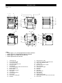
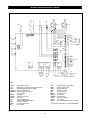
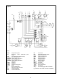
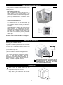
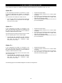
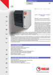
DESCRIPTION OF EQUIPMENT Control and safety thermostats The heater is controlled by three thermostats pre set to the following: Heat exchanger Stainless steel construction easily accessible for inspection and cleaning and maintenance operations. Patented exchange elements made in stainless steel modular sections with large surface area, trapezoidal in section with swirl impressions for which give thermal yields of over 90%. The exchange elements have no welded joints or seams near to the burner flame so as to avoid exposure of any weak points. LM Limit thermostat (100°C) Capillary type. Manual Reset Act as a safety device and shuts down the burner if the heater goes to overheat. The yellow light will flash when in overheat. The LIMIT thermostat is reset by the removal of the plastic cap situated on the control panel inside the heater, and manually pressing the reset button, after first ensuring that the fault has been rectified. (calibrated at 100°C). Replaced cap after resetting thermostat. Flue outlet with integral flue venter to assist dispersal of combustion gasses External casing Encloses all controls giving a good aesthetic appearance and streamlined look whilst allowing for easy inspection. The casing consists of removable panels also includes: A burner compartment, which is totally sealed off, with an inspection door; Radiant heat insulation on the surfaces closest to the heat exchanger; Outlet grille for directing the warm air complete with individually movable horizontal fins. vertical louvers are available on request TR Regulatory thermostat (0 – 90°C) Capillary type. Automatic reset. The thermostat monitors the temperature of the airflow and will shut down the burner if the set level is exceeded (calibrated at 70°C). Once the fan has sufficiently cooled the heat exchanger, the burner will automatically relight. The yellow indication light will flash until the burner relights. If this fault persists the cause should be investigated. SND Control probe (0 – 40°C) Connected in series with the thermostat TR. The probe will start the fan when the temperature reaches 30°C (approximately 30 seconds from burner ignition). When the desired room temperature is reached and the burner shuts down, the probe will allow the fan to run for approximately 3-4 minutes until the heat exchanger has cooled sufficiently. The probe also monitors the operation of the TR thermostat and if a fault is detected will change the yellow flashing light to a continuous on light. In addition to this the SND probe monitors the temperature of the return air and will switch off the fan prior to the 3-4 minute run on time if the heat exchanger has cooled sufficiently (this avoiding cold air flow from the heater). Fan assembly One, two or three axial high air flow single speed single phase fan/motors complete with guards give effective cooling of the combustion / heat exchanger.(single stage and two stage ) and two speed fans (Dual Power). The position of the fan(s) produce greater effective cooling of the combustion chamber, optimising the heat exchange and avoiding overheating. Control and protection equipment This is an electronic circuit board with ionisation flame detection and ignition controls. The equipment controls and monitors the operation of the burner in the following sequence. Checks the differential pressure switch operated by the flue venter is in the closed position and the flue venter is working; Checks the air temperature of the combustion chamber (below 100ºC) Opens the gas solenoid valve; Starts burner ignition; Detects flame signal from flame probe and allows normal heater operation Failure in any of the above sequence will result in the control box shutting the gas valve and stopping the heater The Heater will go to lockout and can be only be reset manually by pressing the red light on the front of the equipment. Differential air pressure switch This switch will shut the gas valve if the flue venter fails or there is an obstruction in the flue. Flue venter This consists of a centrifugal fan which Is run by an electric motor with self-cooling rotor the cooling air is supplied through a duct pipe situated in the axial fan air flow Indication lights These consist of three different coloured lights on the front of the heater: Green light – indicates normal working. Illuminates when the gas solenoid valve opens Yellow light – indicates the operation of the LM, TR and SND thermostat. Red light - to indicate lockout of the heater by the control circuit failure. Gas solenoid valve The multifunctional 1 stage gas valve (Single Stage) and 2 Stage gas valve (Two Stage and Dual Power) Safety solenoid valve A regulatory solenoid valve A pressure regulator A gas filter Reset button to reset the lockout Flue spigot A flue spigot (100mm) is situated at the rear of the heater for connection of flue pipes. Atmospheric multigas burner assembly Consisting of: Galvanized steel manifold Visual monitoring aperture for the electrodes and flame observation 1. 2 or 4 stainless steel burner bars Ignition and Detection electrodes. Combustion air spigot A combustion air spigot (100/150mm) with a safety mesh of less than 16 mm Ø on the rear of the heater allow for connection of combustion air pipes. Note: the type 6 - 7 models are equipped with two gas manifolds, each manifold has an ignition electrode. 5