1
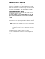
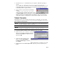
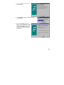
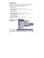
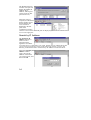
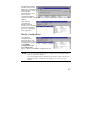
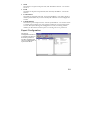
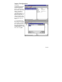
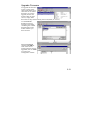
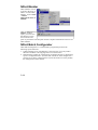
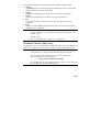
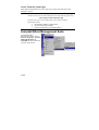
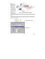
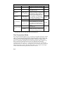
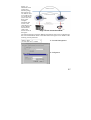
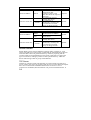
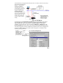
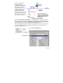
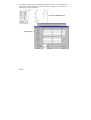
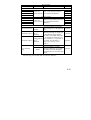
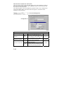
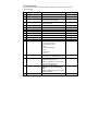
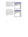
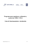
1 NPort Family Software Installation Guide Fourth Edition, May 2004 NPort Family Software Installation Guide The software described in this manual is furnished under a license agreement and may be used only in accordance with the terms of that agreement. Copyright Notice Copyright 2004 Moxa Technologies Co., Ltd. All rights reserved. Reproduction without permission is prohibited. Trademarks MOXA is a registered trademark of Moxa Technologies Co., Ltd. All other trademarks or registered marks in this manual belong to their respective manufacturers. Disclaimer Information in this document is subject to change without notice and does not represent a commitment on the part of Moxa. Moxa provides this document “as is,” without warranty of any kind, either expressed or implied, including, but not limited to, the particular purpose. Moxa reserves the right to make improvements and/or changes to this manual or the product(s) and/or program(s) described herein at any time. Information provided in this manual is intended to be accurate and reliable. However, Moxa Technologies assumes no responsibility for its use, or for any infringements on the rights of fourth parties which may result from its use. This manual could include unintentional technical or typographical errors. Changes are periodically made to the information herein, with the changes incorporated into new editions of the publication. MOXA Internet Services Customer satisfaction is our number one concern. To ensure that customers receive the full benefit of our products, Moxa Internet Services has been set up to provide technical support, driver updates, product information, and user’s manual updates. The following services are provided: E-mail for technical support: address: [email protected] Latest drivers and documents: address: http://www.moxa.com World Wide Web (WWW) site for product information: address: http://www.moxa.com Table of Contents 1 Introduction ........................................................................................1-1 NPort Family Features.....................................................................1-1 Operation Mode Specification Chart................................................1-2 How To Use This Manual.................................................................1-3 2 Initial IP Address Configuration .......................................................2-1 Initializing NPort’s IP Address..........................................................2-1 Factory Default IP Address..............................................................2-2 NPort Management Suite ................................................................2-2 ARP .................................................................................................2-2 Telnet Console .................................................................................2-3 Serial Console (19200, n, 8, 1)........................................................2-4 3 NPort Management Suite ..................................................................3-1 Installing NPort Management Suite .................................................3-1 Configurator .....................................................................................3-4 Broadcast Search .................................................................3-5 Search by IP Address ...........................................................3-6 Modify Configuration.............................................................3-7 Unlock Server .......................................................................3-8 Export Configuration .............................................................3-9 Import Configuration ...........................................................3-11 Upgrade Firmware ..............................................................3-13 NPort Monitor.................................................................................3-14 NPort Batch Configurator ..............................................................3-14 Windows Version (npbc.exe)..............................................3-15 Linux Version (npbc.tgz) .....................................................3-16 Uninstall NPort Management Suite ...............................................3-16 4 Real COM Installer .............................................................................4-1 Add Server Wizard ..........................................................................4-2 Reassigning COM Numbers............................................................4-5 5 Firmware Configuration ................................................................... 5-1 Server Configuration....................................................................... 5-2 Choosing the Proper Operation Mode............................................ 5-4 Host Based / Driver Mode.................................................... 5-4 Pair Connection Mode ......................................................... 5-6 Socket Modes ...................................................................... 5-8 Ethernet Modem Mode (NPort Express ONLY)................. 5-16 Serial Settings............................................................................... 5-21 Access Control.............................................................................. 5-21 Granting Access by IP Address ......................................... 5-22 Granting Access by Port .................................................... 5-22 Inputting IP Addresses....................................................... 5-23 A Revision History ...............................................................................A-1 1 1 Introduction In this chapter, we present the following topics: NPort Family Features Operation Mode Specification Chart How To Use This Manual NPort Family Features The Moxa NPort Family of products covered by the software discussed in this guide consists of NPort Express (DE-211/311), NPort Server Lite (DE-301/302/331/332), and NPort Server Pro (DE-303/308). These products come with the following features: Long range connection through the Intranet/Internet between host and serial device. Secure access control to network hosts. Easy configuration and management. Easy serial port expansion under Host Based / Driver Mode: Up to 128 ports for one Windows 95/98/ME host. Up to 256 ports for one Windows NT/2000/XP host. Serial connection speed of up to 230.4 Kbps. Supports MAC-based IP address configuration. Supports Windows Real COM and Linux Real TTY drivers. Supports configuration export and import for easy deployment. Easy serial device programming with Moxa PComm Lite Serial Control Library—download PComm Lite for free from the Moxa website at www.moxa.com. 1-1 Operation Mode Specification Chart Model NPort Express DE-311 NPort Express DE-211 Windows Real COM driver √ √ √ √ √ √ Linux fixed tty driver √ √ √ √ √ √ Linux real tty driver √ √ √ √ √ √ TCP Server √ √ √ √ √ √ TCP Client √ √ √ √ √ √ UDP Server/Client √ √ √ √ √ √ Pair Connection √ √ √ √ Ethernet Modem √ √ √ Operation Mode NPort Express Module DE-311M NPort Server NPort Server NPort Server Lite DE-301, Lite DE-302, Pro DE-308, DE-331 DE-304, DE-303 DE-332, DE-334 Windows Real COM driver supports Windows 95/98/ME and Windows NT/2000/XP. 1-2 How To Use This Manual First time installation See Chapter 2 for instructions on how to configure your NPort product’s IP address. Configuration See Chapter 3 for instructions on how to install NPort Management Suite, and how to use Configurator, a useful Windows GUI . See Chapter 5 for instructions on how to configure your NPort Product’s firmware via Telnet Console or Serial Console. See Chapter 5 for configuration parameter definitions. Real COM Applications See Chapter 4 for information on expanding the number and reach of your host computer’s COM ports. Linux Real TTY installation Download the Linux tty driver from the Moxa website at www.moxa.com. To see detailed installation instructions under Linux, please refer to the “Installation Guide” in the readme.txt file that is downloaded with the Linux driver. 1-3 2 2 Initial IP Address Configuration When setting up your NPort for the first time, the first thing you should do is configure the Device Server’s IP address. This chapter includes the following sections: Initializing NPort’s IP Address Factory Default IP Address NPort Management Suite the method we recommend ARP Telnet Console Serial Console (119200, n, 8, 1) Initializing NPort’s IP Address 0. Determine whether your NPort needs to use Static IP or Dynamic IP (either DHCP or BootP application). 1. If NPort is used in a Static IP environment, you can use NPort Management Suite, ARP, Telnet Console, or Serial Console (NPort Express ONLY) to configure the new IP address. 2. If NPort is used in a Dynamic IP environment, you can use NPort Management suite, Telnet Console, or Serial Console (NPort Express ONLY) to configure NPort to get an IP address dynamically with DHCP, DHCP/BootP, or BootP. NOTE Consult your network administrator on how to reserve a fixed IP address (for your NPort) in the MAC-IP mapping table when using a DHCP Server or BootP Server. In most applications, you should assign a fixed IP address to your NPort. 2-1 Factory Default IP Address NPorts are configured with the following default private IP address: Default IP address: 192.168.127.254 (IP addresses of the form 192.168.xxx.xxx are referred to as private IP addresses, since it is not possible to directly access a device configured with a private IP address from a public network. For example, you would not be able to ping such a device from an outside Internet connection. NPort applications that require sending data over a public network, such as the Internet, require setting up the server with a valid public IP address, which can be leased from a local ISP.) NPort Management Suite NPort Management Suite consists of some useful utility programs that are used to configure and manage your NPorts. See Chapter 3 for details on how to install NPort Management Suite, and how to use this suite of useful utilities to set up IP addresses and configure your NPort. ARP You can make use of the ARP (Address Resolution Protocol) command to set up an IP address for your NPort. The ARP command tells your computer to associate the NPort’s MAC address with the intended IP address. You must then use Telnet to access the NPort, at which point the Device Server’s IP address will be reconfigured. NOTE In order to use this setup method, both your computer and NPort must be connected to the same LAN. Or, you may use a cross-over Ethernet cable to connect the Device Server directly to your computer’s Ethernet card. Your NPort must be configured with the factory default IP address— 192.168.127.254—before executing the ARP command, as described below. Take the following steps to use ARP to configure the IP address: 1. Obtain a valid IP address for your NPort from your network administrator. 2. Obtain the NPort’s MAC address from the label on its bottom panel. 2-2 3. Execute the ‘arp -s’ command from your computer’s MS-DOS prompt by typing: arp –s 192.168.200.100 00-90-E8-xx-xx-xx This is where 192.168.206.100 is the new IP address and 00-90-E8-xx-xx-xx is the MAC address for your NPort. You will need to change both numbers, as described above in points 1 and 2. 4. Next, execute a special Telnet command by typing: telnet 192.168.200.100 6000 After issuing this command, the Telnet session a Connect failed message will appear, as shown here. The NPort’s IP address should now be updated to the new address, and you can reconnect using either Telnet or Configurator to check that the update was successful. Telnet Console Depending on how your computer and network are configured, you may find it convenient to use network access to set up your NPort’s IP address. This can be done using the Telnet program. NOTE For NPort Express, you must set DIP switch 1 to the OFF position to be able to establish a Telnet connection. NOTE NPort Server Lite and NPort Server Pro are immediately accessible via Telnet, provided they are properly connected to the LAN. 1. From the Windows desktop, click on Start and then select Run. 2. Type telnet 192.168.127.254 (use the correct IP address if different from the default) in the Open text input box, and then click OK. 3. When the Telnet window opens, type 1 to select ansi/vt100 for Console terminal type, and then press Enter. 4. If prompted for the Console password, input the password and then press Enter. 2-3 5. To ensure proper operation, click on the Terminal menu, choose Preferences…, and then make sure VT100 Arrows is checked. 6. Use the keyboard arrow keys to highlight [serverConfig] as shown below, and then press Enter. 7. A window showing the various parameters required to configure the NPort opens up, with configurable parameters enclosed in square brackets. 8. Use the keyboard arrow keys to position the cursor over the first digit of the IP address. Type in the correct IP address and then press Enter to accept this value. 9. Press ESC to return to the main menu, and then Restart to activate the change. Serial Console (19200, n, 8, 1) NOTE This section only applies to the NPort Express Series (NPort Server Pro and NPort Server Lite do NOT have serial console ports). You may use the RS-232 console port to set up the IP address for the NPort Express Family. We suggest using MOXA PComm Terminal Emulator, which is available free of charge as part of the MOXA PComm Lite program suite, to carry out the installation procedure, although other similar utilities may also be used. (Please go to www.moxa.com to download the installation program for 2-4 PComm Lite.) NOTE You must set DIP switch 1 to the ON position to be able to establish a console connection. 1. Plug your NPort Express’s female serial port directly into your computer’s male RS-232 serial port, or use an appropriate converter (refer to the Hardware Installation Guide for details). 2. From the Windows desktop click on Start Terminal Emulator. Programs PComm Lite 3. When the PComm Terminal Emulator window opens, first click on the Port Manager menu item and select Open, or simply click on the Open icon. 4. The Property window opens automatically. From the Communication Parameter page, select the appropriate COM port for the connection, COM1 in this example, and 19200 for Baud Rate, 8 for Data Bits, None for Parity, and 1 for Stop Bits. 5. From the Property window’s Terminal page, select VT100 for Terminal Type and then click OK. 2-5 6. Choose 1 for ansi/vt100 terminal emulation type, and then press Enter. 7. Use the keyboard arrow keys to highlight [serverConfig], and then press Enter to select this option. 8. A window showing the various parameters required to configure NPort Express opens up, with configurable parameters enclosed in square brackets. 9. Use the keyboard arrow keys to position the cursor over the first digit of the IP address. Type in the correct IP address, press ESC to return to the main menu, and then select Restart to activate the change. 2-6 3 3 NPort Management Suite NPort Management Suite consists of five programs—Configurator, Real COM Installer, NPort Monitor, NPort Batch Configurator (Windows and Linux versions), and Uninstall NPort Management Suite—that are designed to make it easy to configure and manage your NPorts. This chapter includes the following sections: Installing NPort Management Suite Configurator • Broadcast Search • Search by IP Address • Modify Configuration • Unlock Server • Export Configuration • Import Configuration • Upgrade Firmware NPort Monitor NPort Batch Configurator • Windows Version (npbc.exe) • Linux Version (npbc.tgz) Uninstall NPort Management Suite Installing NPort Management Suite Follow the steps given below to install NPort Management Suite on your Windows-based computer. 1. Run the Device Server setup program Dssetup.exe. 3-1 2. Click on Next when the Welcome! window opens to proceed with the installation. 3. Select the NPort Management Suite utilities that you would like to install. 4. Click on Next to install program files in the default directory, or click on Browse to select an alternative location. 3-2 5. Click on Next to proceed with the installation. 6. The Installing window reports the progress of the installation. 7. If you select Later, you can always run Configurator or Real COM Installer later from under the Windows Start button (see the appropriate sections below for details). 3-3 Configurator Configurator is a comprehensive Windows GUI that can be used to conveniently configure and maintain multiple NPorts. It is designed to provide you with instantaneous control of all your NPorts, regardless of location. Configurator provides the following useful utilities: Broadcast Search Locate all NPorts that are connected to the PC host’s LAN. Search by IP address Locate a specific NPort by IP address, even if the NPort is located outside the PC host’s LAN. Upgrade Firmware Keep your NPort up to date with the latest Moxa firmware. Modify Configuration Easily reconfigure an NPort’s parameter settings, such as IP address, Netmask, Gateway, port settings, password, etc. Export Configuration Export an NPort configuration to a file on the PC host. Import Configuration Import an NPort Configuration from a file on the PC host to one or more NPorts. To run Configurator, click on Start Programs NPort Management Suite Configurator. After the Configurator window opens, you can use any of the utilities by selecting options 3-4 under the appropriate menu—Locate Server, Firmware, Configuration, View, or Help—or by clicking on an active utility icon. Configurator is very intuitive and quite easy to use. However, you can always refer to Configurator’s help file by selecting Help Topics under Help as shown below. Once the Help window opens, click on the topic that you wish to view. Broadcast Search The Broadcast Search function is used to locate all NPorts that are connected to the same LAN as your computer. NOTE Before modifying an NPort’s configuration, use Broadcast Search or Search by IP Address to locate NPorts connected to the LAN. 3-5 The Broadcast Search window will open and display the Model, IP Address, MAC Address, and Progress (of the search for that particular device). When the search is complete, the Broadcast Search window closes, and the NPorts that were located are displayed in the left pane of the Configurator window. Click on a server name in the left pane to display key information related to that server in the right pane. Search by IP Address The Search by IP Address function is used to locate a particular NPort, regardless of whether or not the server is connected to your LAN. If both your PC and the NPort that you are trying to locate have access to the same LAN, WAN, or even to the Internet, you should be able to use Search by IP Address to locate the NPort. When the Search by IP Address window opens, enter the IP Address of the NPort you wish to locate, and then click OK. 3-6 The Broadcast Search window will open and display key information and the progress of the search for that particular NPort. If an NPort with the specified IP Address cannot be located, consult with your network administrator to get the correct IP address. If the search is successful, the Broadcast Search window closes, and key information related to the server is displayed in the right pane. Modify Configuration To modify the configuration of a particular NPort, first select the NPort’s name to highlight it, and then select Modify Configuration under the Configuration menu, or click on the Modify Configuration icon. NOTE You can simultaneously modify the configurations of multiple NPorts that are of the same model. To select multiple NPorts, hold down the Ctrl key when selecting any additional NPort, or hold down the Shift key to select a group of NPorts. 3-7 The Configuration window opens to the Network Settings page. To modify items, select or deselect the item by clicking in the checkbox next to the item. Click on the OP_Mode, Serial Settings, Access Control, or Password tabs to modify the settings of other parameters. NOTE Detailed information about these configuration parameters is given in Chapter 5, Firmware Configuration. Unlock Server The Unlock Server function is used to open a password protected NPort so that the user can modify its configuration. As shown below, six possible states can appear in the Status column. The meanings of the six states are as follows (note that the term Fixed is borrowed from the standard fixed IP address networking terminology): Locked The NPort is password protected, “Broadcast Search” was used to locate it, and the password has not yet been entered from within the current Configurator session. Unlocked The NPort is password protected, “Broadcast Search” was used to locate it, and the password has been entered from within the current Configurator session. Henceforth during this Configurator session, activating various utilities for this NPort will not require re-entering the server password. 3-8 blank The NPort is not password protected, and “Broadcast Search” was used to locate it. Fixed The NPort is not password protected, and “Search by IP address” was used to locate it. Locked Fixed The NPort is password protected, “Search by IP address” was used to locate it, and the password has not yet been entered from within the current Configurator session. Unlocked Fixed The NPort is password protected, “Search by IP address” was used to locate it, and the password has been entered from within the current Configurator session. Henceforth during this Configurator session, activating various utilities for this NPort will not require re-entering the server password. Export Configuration The Export Configuration function is a handy tool that can be used to produce a text file containing the current configuration of a particular NPort. 3-9 Next, use the Look in drop down menu to navigate to the folder where you want to store the configuration, type a file name in the File name input box, and then click on Open. When you see the Export configuration to file OK message, click OK to return to the Configurator window. You may use the configuration (text) file to change configuration items and/or comment out configuration items, and then import the new configuration into one or more NPorts (see the next section, Import Configuration, for details). Note that the pound sign (#) indicates a comment line. 3-10 Import Configuration The Import Configuration function is used to import an NPort configuration from a file into one or more of the same model NPort. To import a configuration, first select the target servers (use the left mouse button to select servers; simply hold down the Ctrl key when selecting the second, third, etc. server). Use the Look in drop down menu to navigate to the folder containing the configuration text file, click on the file to input the file name into the File name box, and then click on Open. 3-11 At this point, the Configuration window will open to give you the option to select or deselect configuration items. This step is a very important part of the Import Configuration process. For example, when importing the same configuration to multiple servers, you will probably at least want to deselect Server Name and IP Address. If you do not deselect these items, then all of the NPorts that you are importing to will end up with the same Server Name and IP Address! NOTE When importing the same configuration to multiple NPorts, be sure to deselect items such as Server Name and IP Address. Otherwise, you will end up with more than one server with the same name and IP Address. When the Progress column reads OK for each of the servers whose configuration is being updated, click on Close, located in the upper left corner of the Set Configuration window, to return to the Configurator window. 3-12 Upgrade Firmware To upgrade the firmware of one or more of the same model NPort, first select the servers whose firmware you wish to upgrade (use the left mouse button to select servers; simply hold down the Ctrl key when selecting the second, third, etc. server). Use the Look in dropdown menu to navigate to the folder containing the *.ROM firmware file for the model of NPort you have selected. When the Progress column reads OK for each of the servers whose firmware is being upgraded, click on Close to return to the Configurator window. 3-13 NPort Monitor NPort Monitor is used to monitor the ports of NPorts. To start NPort Monitor, click on Start NPort Management Suite Monitor. After the NPort Server Monitor window opens, you can access the help file to learn how to monitor the ports of your NPorts. The help file contains complete information on how to use NPort Monitor. NPort Batch Configurator NPort Batch Configurator is a command line program that performs the following special functions. 1. Update multiple Nport’s IP addresses at the same time. You only need to maintain one MAC to IP mapping table to use this function. 2. Simultaneously update the configurations of multiple Nports by maintaining special “configuration files” (text files that contain all of the configuration settings for an NPort). Administrators can use this function to easily modify the configuration of their NPorts. 3-14 NPort Batch Configurator provides the following useful runtime options: change The change option is used to change the IP addresses of one or more NPort that are connected to the PC host’s LAN. setting Modify the configurations of one or more of the same model NPort. export Export the configuration of one NPort to a file on the PC host. list List all NPorts that are currently connected to the same LAN as your computer. help Display the NPort Batch Configurator help file to see the exact format for using the above commands. NOTE The change option is unique to NPort Batch Configurator. This option provides a handy way to simultaneously update the IP addresses of multiple NPorts. Example usage: Run <installed directory>\npbc.exe –c changeip.txt Windows Version (npbc.exe) The Windows version of NPort Batch Configurator, npbc.exe, is provided for the hard core programmer who still insists on doing things the old fashioned way. NOTE More details about the Windows version of NPort Batch Configurator can be found by accessing the NPort Batch Configurator help file. After installing NPort Management Suite in the default folder, npbc.exe will be located in the folder: c:\Program Files\NPortSuite\Utilities You run npbc.exe by typing npbc (followed by options, as described in the help file) from the DOS command line. 3-15 Linux Version (npbc.tgz) NPort Batch Configurator for Linux, npbc.tgz, has the same functions as the Windows version. NOTE To install NPort Batch Configurator for Linux, find the file npbc.tgz, which is located on the NPort Software CD in the following directory: nport\software\linux\i386\npconfig You may also refer to the readme file on the software CD for information about: 1. IP and MAC address configuration 2. Export Configuration Table 3. Import Configuration to multiple NPorts. Uninstall NPort Management Suite To uninstall NPort Management Suite, click on Start Programs NPort Management Suite Uninstall and then follow the onscreen instructions. 3-16 4 4 Real COM Installer In this chapter, we discuss the basic tasks involved in configuring your NPort, and discuss the various operation modes that are available. This chapter includes the following sections: Add Server Wizard Reassigning COM Numbers The main purpose of Real COM Installer is to set up your host computer to communicate with particular NPorts configured for Host Based / Driver Mode. The Add Server Wizard utility is used to carry out this procedure. You will also need to use Real COM Installer’s Map Port function to reassign COM port numbers for your NPorts. NOTE NPort’s Windows 95/98/ME/NT/2000/XP drivers are bundled with NPort Management Suite. To expand the number and range of your host computer’s COM ports, use “Real COM Installer” to assign COM numbers to NPort’s serial ports. The procedure for doing this is exactly the same for all Windows platforms. 4-1 Add Server Wizard Follow the steps given below to set up your host computer to communicate with NPorts configured for Host Based / Driver Mode. 1. To start Real COM Installer, click on Start Programs NPort Managemen t Suite COM Port Mapping Real COM Installer. 2. When the Real COM Installer window opens, select Add Server Wizard. 3. Make sure you have connected the NPort to the network, and then click on Next to proceed. 4-2 4. You can select Automatically search the LAN or Manually enter IP address. The second option allows you to search for NPorts that are not connected directly to your host’s LAN. 5. Click on the Model of the server you would like to add, and then click on Next to continue. 4-3 6. The NPort’s serial ports are mapped sequentially, starting from the smallest available COM number. Higher COM numbers that are already assigned to other ports will be skipped. NOTE After you install an NPort, you can use Real COM Installer’s Map Port function to reassign COM numbers to the server’s serial ports. 7. Click on Next to save the settings to your host computer and the NPort. 4-4 8. Select whether or not you would like to enable the COM ports that were just assigned, and then click on Finish. 9. If you are currently running programs that access the newly added NPort’s serial port(s), be sure to shut down those programs before clicking on Yes in the following window. 10. Real COM Installer will now display the NPort and ports that were just added to your host computer. Reassigning COM Numbers Follow the instructions given below to reassign COM numbers to NPort ports. 1. Highlight the port whose COM number you wish to reassign (in the right pane of the Real COM Installer window), as shown below, and then select Map Port under the Port menu, or click on the Map Port icon (the fourth icon from the left). 4-5 2. The Port Properties window will open, at which time you will be able to view the COM number currently assigned to the port (COM3 for this example). Transmission Mode: Hi-performance mode is the default for Tx mode. If the driver completes sending data out to the NPort, the driver will respond “Tx Empty” to the program. Under classical mode, the driver will not notify the user’s program that Tx is completed until all Tx data has been sent out from the NPort; this mode will cause lower throughput. If you want to ensure that all data is sent out before further processing, classical mode is recommended. Enable/Disable Tx/Rx FIFO. If disabled, NPort will send one byte each time the Tx FIFO becomes empty; and an Rx interrupt will be generated for each incoming byte. This will result in a faster response and lower throughput. If you want to use XON/XOFF flow control, we recommend setting FIFO to Disable. 4-6 Fast Flush (only flush local buffer) (1) We have added one optional “Fast Flush” function in our new NPort Real COM driver. NPort Management Suite for 1 G NPort adds this function after version 3.2. (2) For some applications, the user’s program will use the Win32 “PurgeComm()” function before it reads or writes data. With our design, after the program uses this PurgeComm() function, the NPort driver will keep querying NPort firmware buffer, rather than just flushing the local buffer. This kind of design is used because of some special considerations. However, it might take more time (about several hundred milliseconds) than a native COM1, because it needs to work via Ethernet. That’s why the native COM ports on the motherboard can work fast with this function call, but NPort requires much more time. In order to accommodate other applications that require a faster response time, the new NPort driver implements a new “Fast Flush” option. Note that by default, this function is disabled. (3) To begin with make sure there are some “PurgeComm()” functions being used in your application program. In this kind of situation, you might find that your NPort exhibits a much poorer operation performance than when using the native COM1 port. Once you have enabled the “Fast Flush” function, you can check to see if there has been an improvement in performance. (4) By default, the optional “Fast Flush” function is disabled. If you would like to enable this function, from the “Real COM Installer”, double click on the COM ports that are mapped to the NPort, and then select the “Fast Flush” checkbox. You should find that when “Fast Flush” is enabled, the NPort driver will work faster with “PurgeComm().” 3. Click on the Map to drop down window and then select the new COM number (COM6 for the example shown here), and then click OK. 4. You will now be able to view the new COM port number in the Real COM Installer window. To save the setting, select Save Configuration under the Server menu, or click on the Save all Servers icon (the leftmost icon). 4-7 5. Make sure that any programs currently accessing the COM ports are shut down, and then click Yes to accept the change, and restart the NPort. 4-8 5 5 Firmware Configuration In this chapter, we discuss the basic tasks involved in configuring your NPort, and discuss the various operation modes that are available. This chapter includes the following sections: Server Configuration Choosing the Proper Operation Mode • Host Based / Driver Mode • Pair Connection Mode • Socket Modes TCP Server TCP Client UDP Server/Client • Ethernet Modem Mode (NPort Express ONLY) Using Ethernet Modem AT Commands S Registers Serial Settings Access Control • Granting Access by IP Address • Granting Access by Port • Inputting IP Addresses 5-1 Server Configuration The following figures show the basic parameters that must be set up before you can begin using your NPort. Refer to the table on the next page to see details of the meaning of each parameter. Console Management NOTE Click on the Password tab to modify the NPort’s password. Configurator 5-2 Setting Server Model Server Name Serial Number IP Configuration Ethernet Status MAC Address (Static) IP Address Netmask Gateway Password Server Configuration Value Comments DE-xxx Set at the factory. This option is useful for specifying the location or alpha-numeric application of different servers. alpha-numeric Set at the factory. Static IP Choose one of the four DHCP values at the left to DHCP/BOOTP determine how the IP address will be configured. BOOTP 10M bps Indicates the Ethernet connection status 100M bps The MAC (Media Access 48-bit number Control) address is a unique identifier set at the factory. 32-bit number; The current IP address; identifies the server on the default = 192.168.127.254 TCP/IP network. 32-bit number; Identifies the server as belonging to a Class A, B, or default = 255.255.255.0 C network. IP address of the router that 32-bit number provides network access outside the server’s LAN. alpha-numeric Console/Configurator password Necessity --Optional --Required ----Required Required Optional Optional NOTE The Firmware will retry 3 times every 30 seconds until it gets the IP settings from the DHCP/BootP server. The timeout times are 1, 3, and 5 seconds. If the DHCP/BootP server is not available, the firmware will use the default IP address, netmask, and gateway for network settings. 5-3 Choosing the Proper Operation Mode In this section, we describe the various NPort operation modes. The options include an operation mode that uses a driver installed on the host computer, operation modes that rely on TCP/IP socket programming concepts, and operation modes that typically involve communication between pairs of appropriately configured NPorts. Host Based / Driver Mode Host Based / Driver Mode uses a Moxa supplied driver to establish a transparent connection between host and serial device, by creating a virtual local COM port on the host computer for each of the NPort’s serial ports. NOTE The Moxa driver used for Host Based / Driver Mode is installed automatically on your computer when you install NPort Management Suite. The important point is that Host Based / Driver Mode allows users to continue using RS-232/422/485 serial communications software that was written for pure serial communications applications. The driver intercepts data sent to the host’s COM port, packs it into a TCP/IP packet, and then redirects it through the host’s Ethernet card. At the other end of the connection, the NPort accepts the Ethernet frame, unpacks the TCP/IP packet, and then transparently sends it to the appropriate serial device attached to one of the NPort’s serial ports. NOTE Host Based / Driver Mode allows several hosts to have access control of the same NPort. The Moxa driver that comes with your NPort controls host access to attached serial devices by checking the host’s IP address. Use Configurator to adjust the Access Control Table—you may add host access either by port or by server. Host Based / Driver Mode allows users to set up more advanced communications topologies between remote hosts and serial devices connected to one or more NPort. Using this operation mode, it is possible for several hosts to divide usage of a multiport NPort’s ports, or share the same port belonging to one particular NPort. 5-4 Figure 3.1 illustrates a Host Based / Driver Mode topology that consists of two hosts that share access to two NPorts. The NPort Server Pro unit is connected to several serial devices, with half of the ports Fig. 3.1: Host Based / Driver Mode relegated to Host A, and the other half to Host B. The NPort Server Lite unit is connected to two serial devices, and can be configured so that one or both of the hosts are allowed access to these two devices. The following figures show the additional parameters that can be configured for Host Based / Driver Mode. Refer to the table after the figures to see details of the meaning of each parameter. Console Management Configurator 5-5 Host Based / Driver Mode Notes Necessity The TCP port through which data TCP data port 950 Required is sent. TCP command The TCP port through which 966 Required commands are sent. port Once the NPort receives both Delimiter 1 ASCII code for delimiters through its serial port, Optional the 1st delimiter it immediately packs all data (Hex) currently in its buffer and sends it out the NPort’s Ethernet port. Delimiter 2 ASCII code for Note: Delimiter 2 is optional. If the 2nd delimiter left blank, then Delimiter 1 alone Optional (Hex) trips clearing of the buffer.* Disabled. blank (or 0) Forces the NPort’s TCP/IP Force transmit protocol software to try to pack Optional serial data received during the (ms) 1 – 65535 ms specified time into the same data frame.* TCP connection is never closed 0 by this device. TCP alive check TCP connection is automatically Optional time closed by this device if there is no 1 – 99 min. TCP activity for the given time. * If the size of the serial data received is greater than 1K, the NPort will automatically pack the data and send it to the Ethernet. Setting Value Pair Connection Mode Pair Connection Mode employs two 1-port NPorts in tandem, and can be used to remove the 15-meter distance limitation imposed by the RS-232 interface. One NPort is connected from its RS-232 port to the COM port of a PC or other type of computer, such as hand-held PDAs that have a serial port, and the serial device is connected to the RS-232 port of the other NPort. The two NPorts are then connected to each other with a cross-over Ethernet cable, both are connected to the same LAN, or in a more advanced setup, they communicate with each other over a WAN (i.e., through one or more routers). Pair Connection Mode transparently transfers both data and modem control signals (although it cannot transmit the DCD signal) between the two NPorts. 5-6 Figure 3.2 illustrates a Pair Connection Mode topology that consists of two NPorts used to provide access to a serial device (in this case, the PLC). This example illustrates that access to the serial device can be provided to non-PC hosts, such as the Fig. 3.2: Pair Connection Mode Writer shown in the figure. The following figures show the additional parameters that can be configured for Pair Connection Mode. Refer to the tables below the figures to see details of the meaning of each parameter. Console Management Configurator 5-7 Pair Connection (Master) Value Notes Necessity IP address of another NPort, configured for Pair Connection (Slave), with Remote IP address valid IP Required which this NPort can request a connection. TCP connection is never 0 closed by this device. TCP connection is Optional TCP alive check time automatically closed by this 1 – 99 min. device if there is no TCP activity for the given time. Setting Pair Connection (Slave) Value Notes Allows contact with only the valid IP specified remote IP address. Remote IP address Allows contact with any blank remote Master. TCP connection is never 0 closed by this device. TCP connection is TCP alive check time automatically closed by this 1 – 99 min. device if there is no TCP activity for the given time. Setting Necessity Optional Optional Socket Modes Socket Mode consists of three different operation modes: TCP Server, TCP Client, and UDP Server/Client. Keep in mind that the main differences between TCP and UDP is that TCP guarantees delivery of data by requiring that the recipient sends an acknowledgement to the sender. UDP does not require this type of verification, making it possible to offer speedier delivery. UDP also allows multicasting of data to groups of IP addresses. TCP Server TCP Server operation mode is designed for use with serial devices that act as servers. That is, they passively wait for other devices to contact them and request that a TCP connection be established between the two devices. Once a connection is established, data transmission can proceed in both directions. It 5-8 also means that your application software acts as a Client, in that it can actively poll remote serial devices. Figure 3.3 illustrates a TCP Server Mode topology that consists of one NPort connected by a serial cable to a router’s console port. Working from the notebook computer, the user can request that the NPort open a port, and in this way access the router’s serial console utility. Fig. 3.3: TCP Server Note that leaving the Destination IP address option blank allows any remote networked device to request a connection. Inputting one IP address for this option means that only a remote device with that IP address is allowed to establish a TCP connection. Also note that the Delimiter 1, Delimiter 2, and Force transmit options are used to activate the optional Data Packing function. The following figures show the additional parameters that can be configured for TCP Server Mode. Refer to the tables below the figures to see details of the meaning of each parameter. Console Management Configurator 5-9 TCP Server Setting Value Notes Necessity The TCP port that other devices must use to contact this device. To TCP port valid port number avoid conflicts with standard TCP Required ports, the default is set to 4001. Allows contact with only the Destination IP valid IP specified remote IP address. Optional Allows contact with any remote addr blank networked device. Once the NPort receives both Delimiter 1 ASCII code for delimiters through its serial port, Optional the 1st delimiter it immediately packs all data (Hex) currently in its buffer and sends it out the NPort’s Ethernet port. Delimiter 2 ASCII code for Note: Delimiter 2 is optional. If the 2nd delimiter left blank, then Delimiter 1 alone Optional (Hex) trips clearing of the buffer.* Disabled. blank (or 0) Forces the NPort’s TCP/IP Force transmit protocol software to try to pack Optional serial data received during the (ms) 1 – 65535 specified time into the same data frame. * Disabled. blank (or 0) TCP connection is automatically Optional Inactivity time closed by this device if the serial 1 – 65535 ms port is idle for the given time. TCP connection is never closed 0 by this device. TCP alive check Optional TCP connection is automatically time closed by this device if there is no 1 – 99 min. TCP activity for the given time. * If the size of the serial data received is greater than 1K, the NPort will automatically pack the data and send it to the Ethernet. TCP Client The TCP Client operation mode is designed for use with serial devices that act as clients. That is, they actively request that a TCP connection be established with another device. Once the connection is established, data transmission can proceed in both directions. 5-10 Figure 3.4 illustrates a TCP Client Mode topology that consists of one NPort connected by a serial cable to a Card Reader. The NPort can be configured so that when someone swipes their card, the device server requests a connection from the computer, after which the card’s data is sent over the Ethernet connection. Fig. 3.4: TCP Client Note that the Destination IP address is a required option. This means that the device can only be set up to request service from one remote networked device. We should also point out that the Delimiter 1, Delimiter 2, and Force transmit options are used to activate the optional Data Packing function. The following figures show the additional parameters that can be configured for TCP Client Mode. Refer to the table below the figures to see details of the meaning of each parameter. Console Management Configurator 5-11 TCP Client Setting Notes Necessity Allows connection with only the Destination IP addr valid IP Required specified remote IP address. Specific TCP port through which valid port the remote IP address listens TCP port Required number over the TCP connection. Attempts to establish a TCP connection as soon as the NPort Startup is powered on. Required TCP connect Attempts to establish a TCP Any connection as soon as the NPort Character starts receiving serial data. Once the NPort receives both ASCII code delimiters through its serial port, for the 1st Optional Delimiter 1 (Hex) it immediately packs all data delimiter currently in its buffer and sends it out the NPort’s Ethernet port. ASCII code Note: Delimiter 2 is optional. If for the 2nd Delimiter 2 (Hex) left blank, then Delimiter 1 alone Optional delimiter trips clearing of the buffer. * blank (or 0) Disabled. Forces the NPort’s TCP/IP protocol software to try to pack Optional Force transmit (ms) serial data received during the 1 – 65535 specified time into the same data frame. * blank (or 0) Disabled. TCP connection is automatically Optional Inactivity time 1 – 65535 ms closed by this device if the serial port is idle for the given time. TCP connection is not closed 0 due to an idle serial line. TCP connection is automatically Optional TCP alive check time closed by this device if there is 1 – 99 min. no TCP activity for the given time. * If the size of the serial data received is greater than 1K, the NPort will automatically pack the data and send it to the Ethernet. 5-12 Value UDP Server/Client The UDP Server/Client operation mode is designed for applications that need speedier data transmission, or that make use of UDP’s broadcast and multi-cast capabilities. Keep in mind that UDP differs from TCP in that a UDP transmission does not first require a connection to be opened before sending data, and the receiving party does not issue acknowledgements to the sender. Figure 3.5 illustrates a UDP Server/Client Mode topology that consists of one NPort connected by a serial cable to a Card Reader. The NPort automatically transmits the card’s data over the Ethernet to multiple computers. We should point out that the Delimiter 1, Delimiter 2, and Force transmit options are used to activate the optional Data Packing function. Fig. 3.5: UDP Server/Client 5-13 The following figures show the additional parameters that can be configured for UDP Server/Client Mode. Refer to the table below the figures to see details of the meaning of each parameter. Console Management Configurator 5-14 Server/Client Setting Value Notes Necessity (serial to LAN) Dest. IP addr 1 Dest. IP addr 2 Dest. IP addr 3 Dest. IP addr 4 A host or a Data is sent from the NPort to group of hosts. these remote IP addresses. Required Optional Optional Optional (LAN to serial) Src. IP addr 1 Src. IP addr 2 Src. IP addr 3 Src. IP addr 4 Optional Allows receipt of data from only Optional A host or a these specified remote IP group of hosts. addresses. Optional Optional Used by the NPort to listen for data coming in over the Ethernet Required line. ASCII code for Once the NPort receives both delimiters through its serial port, Optional Delimiter 1 (Hex) the 1st it immediately packs all data delimiter currently in its buffer and sends it out the NPort’s Ethernet port. ASCII code for Note: Delimiter 2 is optional. If Delimiter 2 (Hex) the 2nd Optional left blank, then Delimiter 1 delimiter alone trips clearing of the buffer. * blank (or 0) Disabled. Forces the NPort’s TCP/IP Force transmit protocol software to try to pack Optional (ms) serial data received during the 1 – 65535 specified time into the same data frame. * If the size of the serial data received is greater than 1K, the NPort will automatically pack the data and send it to the Ethernet. Local Listen Port valid port number 5-15 Ethernet Modem Mode (NPort Express ONLY) The Ethernet Modem operation mode is designed for use with legacy operating systems, such as MS-DOS, that do not support TCP/IP Ethernet. By connecting a 1-port NPort’s (applies to models DE-211/311/311M) serial port to the MS-DOS computer’s serial port, it is possible to use legacy software originally designed to transmit data via modem, but now transmit the data over the Ethernet. Figure 3.6 illustrates an Ethernet Modem Mode topology that consists of two or more single-port NPorts. One device server is connected to a computer running DOS, Fig. 3.6: Ethernet Modem Mode and the other device servers are connected by a serial cable to CNC machines. The NPort automatically transmits the card’s data over the Ethernet to multiple computers. When wishing to “dial out” over the Ethernet, the user simply uses the remote NPort’s IP address in place of the phone number as illustrated in the figure. 5-16 Using Ethernet Modem Dial-in NPort Express listens for a TCP/IP connection request from the remote Ethernet modem or host. NPort Express’s response depends on the ATS0 value, as outlined below. ATS0=0 (default): NPort Express will temporarily accept the TCP connection and then send the “RING” signal out through the serial port. The serial controller must reply with “ATA” within 2.5 seconds to accept the connection request, after which NPort Express enters data mode. If no “ATA” command is received, NPort Express will disconnect after sending three “RING” signals. ATS0≧1: NPort Express will accept the TCP connection immediately and then send the “CONNECT <baud>” command to the serial port, in which <baud> represents the baud rate of NPort Express’s serial port. After that, NPort Express immediately enters data mode. Dial-out NPort Express accepts the AT command “ATD <IP>:<TCP port>” from the serial port and then requests a TCP connection from the remote Ethernet Modem or PC. This is where <IP> is the IP address of the remote Ethernet modem or PC, and <TCP port> is the TCP port number of the remote Ethernet modem or PC. Once the remote unit accepts this TCP connection, NPort Express will send out the “CONNECT <baud>” signal via the serial port and then enter data mode. Disconnection request from local site When NPort Express is in data mode, the user can drive the DTR signal to OFF, or send “+++” from the local serial port to NPort Express. NPort Express will enter command mode and return “NO CARRIER” via the serial port, and then input “ATH” to shut down the TCP connection after 1 second. NOTE The “+++” command cannot be divided. The “+” character can be changed in register S2, and the guard time, which prefixes and suffixes the “+++” in order to protect the raw data, can be changed in register S12. 5-17 Disconnection request from remote site After the TCP connection has been shut down by the remote Ethernet modem or PC, NPort Express will send the “NO CARRIER” signal via the serial port and then return to command mode. The following figures show the additional parameters that can be configured for TCP Client Mode. Refer to the table below the figures to see details of the meaning of each parameter. Console Management Configurator Ethernet Modem Notes The TCP port that other devices valid must use to contact this device. To TCP port port No. avoid conflicts with standard TCP ports, the default is set to 4001. Allows connection with only the Destination IP addr valid IP specified remote IP address. TCP connection is not closed due to 0 an idle serial line. TCP alive check time TCP connection is automatically 1 – 99 closed by this device if there is no min. TCP activity for the given time. Setting 5-18 Value Necessity Required Optional Optional AT Commands NPort Express supports the following common AT commands used with a typical modem: No. AT command 1 ATA 2 ATD <IP>:<Port> 3 ATE 4 5 6 7 8 9 10 11 12 13 14 15 16 17 Description Remarks Answer manually Dial up the IP address : Port No. ATE0=Echo OFF ATE1=Echo ON (default) ATH0=On-hook (default) ATH ATH1=Off-hook ATI, ATI0, ATI1, ATI2 Modem version reply “OK” only ATL Speaker volume option reply “OK” only ATM Speaker control option reply “OK” only ATO On line command ATP, ATT Set Pulse/Tone Dialing mode reply “OK” only ATQ0, ATQ1 Quiet command (default=ATQ0) ATSr=n Change the contents of S register See “S registers” ATSr? Read the contents of S register See “S registers” Result code type ATV ATV0 for digit code, ATV1 for text code 0=OK 1=connect (default) 2=ring 3=No carrier 4=error Reset (disconnect, enter command ATZ mode and restore the flash settings) Serial port DCD control AT&C AT&C0=DCD always on AT&C1=DTE detects connection by DCD on/off (default) Serial port DTR control AT&D AT&D0=recognize DTE always ready AT&D1, AT&D2=reply DTE when DTR On (default) AT&F Restore manufacturer’s settings 5-19 18 19 20 21 22 AT&G AT&R AT&S AT&V AT&W Select guard time Serial port RTS option command Serial port DSR control View settings Write current settings to flash for next boot up reply “OK” only reply “OK” only reply “OK” only S Registers No. S Register 1 S0 2 S1 3 S2 4 5 6 7 S3 S4 S5 S6 8 S7 9 S8 10 S9 11 S10 12 S11 13 S12 5-20 Description & default value Ring to auto-answer (default=0) Ring counter (always=0) Escape code character (default=43 ASCII “+”) Return character (default=13 ASCII) Line feed character (default=10 ASCII) Backspace character (default= 8 ASCII) Wait time for dial tone (always=2, unit=sec) Wait time for carrier (default=3, unit=sec) Pause time for dial delay (always=2, unit=sec) Carrier detect response time (always=6, unit 1/10 sec) Delay for hang up after carrier (always=14, unit 1/10 sec) DTMF duration and spacing (always=100 ms) Escape code guard time (default=50, unit 1/50 sec) to control the idle time for “+++” Remarks no action applied no action applied no action applied no action applied no action applied no action applied Serial Settings You should access Console Manager’s Serialport page, or Configurator’s Serial Settings page to modify a port’s Baud Rate, Parity, Data Bits, Stop Bit, Flow Control, and UART FIFO. Console Management Configurator Access Control Configurator’s Access Control page allows you to add or remove host access to the NPort. Access to NPorts is controlled by IP address. That is, if a host’s IP address is in the server’s access table, then the host will be allowed access to the server. You may add access control by IP Address and by Port. 5-21 Granting Access by IP Address Use the grant access control by IP Address method if you wish to grant access to a host with a particular IP address. Note that the top IP address belongs to the NPort, and the IP address(es) below that are for hosts that have been granted access. By clicking on the various IP addresses and ports to highlight them, you can easily see the types of functions (Add IP, Add Port, etc.) that are allowed. Granting Access by Port Use the grant access control by Port method if you wish to grant a particular host access to a specific port. Note that the IP address at the top belongs to the NPort, and the server’s ports are listed under that. Expand the list under a particular port to view all IP addresses that have been granted access to that port. By clicking on the various IP addresses and ports to highlight them, you can easily see the types of functions (Add IP, Add Port, etc.) that are allowed. 5-22 Inputting IP Addresses There are two options to choose from when inputting IP addresses. The Single Host option is easy to understand. Simply enter the IP address of the host that is being granted access to the NPort. The meaning of the A Group of Host option is a little bit more complicated. In this case, you must enter both an IP Address and Netmask. When written in binary form, the 1-digits in the Netmask determine that part of the IP address for which all IP addresses in the Group are the same. For example, if IP Address = 192.168.100.200 and Netmask = 255.255.255.0, as shown below, then any IP address of the form 192.168.100.xxx would be included in the group. 5-23 A A Document Edition 3 rd Revision History Revision Date Revision Details November 15, 2002 This version of the manual represents a major revision from the previous version. 1. All NPort related software is installed when the user installs NPort Management Suite. 2. NPort Manager has been renamed Real COM Installer. 3. Host Based Mode has been renamed Host Based / Driver Mode. 4. The firmware version discussed in this manual no longer supports Single Host Mode. 5. The previous Custom Mode is essentially the new Host Based / Driver Mode. 6. Host Based / Driver Mode now supports the Data Packing function. A-1 4th May 12, 2004 1. Updated the edition of this manual on the title page. 2. Changed the new Moxa logo on the title page. 3. p. 4-7 Added descriptions on newly-added function “Fast Flush”. A-2