1
Operating Instructions Edition 04/2006
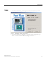
SIMATIC Industrial PC SIMATIC Panel PC 577
Industrial PC
Panel PC 577
simatic
DOCUMENTATION
Preface
Safety instructions and
general notes
1
SIMATIC
Description
2
Industrial PC
SIMATIC Panel PC 577
Planning use
3
Installation
4
Connecting
5
Commissioning
6
Operation and configuration
7
Operating
8
Integration in TIA
9
Operating Instructions
Servicing and maintenance
10
Alarm, error and system
messages
11
Troubleshooting and FAQs
12
Technical specifications
13
Detailed descriptions
14
Appendix
Release 04/2006
A5E00798484-01
A
Safety Guidelines
This manual contains notices you have to observe in order to ensure your personal safety, as well as to prevent
damage to property. The notices referring to your personal safety are highlighted in the manual by a safety alert
symbol, notices referring only to property damage have no safety alert symbol. These notices shown below are
graded according to the degree of danger.
Danger
indicates that death or severe personal injury will result if proper precautions are not taken.
Warning
indicates that death or severe personal injury may result if proper precautions are not taken.
Caution
with a safety alert symbol, indicates that minor personal injury can result if proper precautions are not taken.
Caution
without a safety alert symbol, indicates that property damage can result if proper precautions are not taken.
Notice
indicates that an unintended result or situation can occur if the corresponding information is not taken into
account.
If more than one degree of danger is present, the warning notice representing the highest degree of danger will
be used. A notice warning of injury to persons with a safety alert symbol may also include a warning relating to
property damage.
Qualified Personnel
The device/system may only be set up and used in conjunction with this documentation. Commissioning and
operation of a device/system may only be performed by qualified personnel. Within the context of the safety notes
in this documentation qualified persons are defined as persons who are authorized to commission, ground and
label devices, systems and circuits in accordance with established safety practices and standards.
Prescribed Usage
Note the following:
Warning
This device may only be used for the applications described in the catalog or the technical description and only in
connection with devices or components from other manufacturers which have been approved or recommended by
Siemens. Correct, reliable operation of the product requires proper transport, storage, positioning and assembly
as well as careful operation and maintenance.
Trademarks
All names identified by ® are registered trademarks of the Siemens AG. The remaining trademarks in this
publication may be trademarks whose use by third parties for their own purposes could violate the rights of the
owner.
Disclaimer of Liability
We have reviewed the contents of this publication to ensure consistency with the hardware and software
described. Since variance cannot be precluded entirely, we cannot guarantee full consistency. However, the
information in this publication is reviewed regularly and any necessary corrections are included in subsequent
editions.
이 기기는 업무용(A급) 전자파 적합기기로서 판매자 또는 사용자는 이 점을 주의하시기 바라며 가정 외의 지역에서 사용하는 것을 목적으로 합니다.
Siemens AG
Automation and Drives
Postfach 48 48
90437 NÜRNBERG
GERMANY
Order No.: A5E00798484-01
Edition 04/2006
Copyright © Siemens AG
200420052006.
Technical data subject to change
Preface
This manual
Purpose of the manual
This manual provides information based on the requirements defined by DIN 8418 regarding
mechanical engineering documentation. This information relates to the device, its place of
use, transport, storage, installation, use and maintenance.
This manual is intended for the following target groups:
• Users
• Commissioning engineers
• Service technicians
• Maintenance technicians
Please read the section "Safety instructions and general notes" carefully.
Knowledge required
A solid background in personal computers and Microsoft operating systems is required to
understand this manual. General knowledge in the field of automation control engineering is
recommended.
Scope of this manual
This manual applies to devices with the order numbers 6AV782.…
SIMATIC Panel PC 577
Operating Instructions, Release 04/2006, A5E00798484-01
iii
Preface
Related documentation
The documentation for the Panel PC includes the following sections:
• SIMATIC Panel PC 577, Operating Instructions (compact) with the following information:
– Commissioning
– Legal information
• SIMATIC Panel PC 577, Operating Instructions
The documentation is supplied with the Panel PC in electronic form as a PDF file on the
"Documentation & Drivers" CD. QuickStart for the Panel PC 577 is also supplied in printed
form. The documentation is available in German, English, French, Italian and Spanish.
Additional information about the Windows operating system is available in the Internet at the
Microsoft homepage, "www.Microsoft.com".
Online Availability
The following links will bring you directly to the technical documentation collection for
SIMATIC products and systems in the languages German, English, French, Italian and
Spanish.
• SIMATIC Guide Technische Dokumentation in Deutsch:
http://www.ad.siemens.de/simatic/portal/html_00/techdoku.htm
• SIMATIC guide to technical documentation in English:
http://www.ad.siemens.de/simatic/portal/html_76/techdoku.htm
Conventions
The following text notation will facilitate reading this manual:
Representation
Scope
"File"
•
•
•
Terminology that occurs in the user interface, e.g., dialog
names, tabs, buttons, menu commands.
Inputs required, e.g., limit values, tag values
Path information
"File > Edit"
Operational sequences, e.g., menu items/shortcut menu items.
<F1>, <Shift>+<F1>
Keys and key combinations
The term "Panel PC 577", "control unit" and "computer unit" is uniformly refered to as the
"device" in these operating instructions. The full term is only used when a concrete reference
is necessary.
Note
A note is important information about the product, handling the product or a reference to
specific sections of the documentation that require special consideration.
iv
SIMATIC Panel PC 577
Operating Instructions, Release 04/2006, A5E00798484-01
Preface
Trademarks
All names labeled with ® symbol are registered trademarks of Siemens AG. Other names
used in this documentation may be trademarks, the use of which by third parties for their
own purposes could violate the rights of the owner.
HMI®
SIMATIC®
SIMATIC HMI®
SIMATIC ProTool®
SIMATIC WinCC®
SIMATIC WinCC flexible®
Panel PC 577®
Panel PC 677®
Panel PC 877®
Additional support
Representatives and offices
If you have questions concerning the use of the described product which are not answered in
this manual, please contact the Siemens representative in your area.
Find your contact partner at:
http://www.siemens.com/automation/partner
A guide to the technical documentation for the various SIMATIC products and systems is
available at:
http://www.siemens.com/simatic-tech-doku-portal
The online catalog and the online ordering system is available at:
http://mall.automation.siemens.com
Training center
To familiarize you with automation systems, we offer a variety of courses. Please contact
your regional training center or the central training center in D-90327 Nuremberg, Germany.
Phone: +49 (911) 895-3200
Internet: http://www.sitrain.com
SIMATIC Panel PC 577
Operating Instructions, Release 04/2006, A5E00798484-01
v
Preface
Technical support
You can reach the technical support for all A&D products
via the support request form on the web:
• http://www.siemens.com/automation/support-request
• Phone: + 49 180 5050 222
• Fax: + 49 180 5050 223
Additional information about our technical support is available in the Internet at:
http://www.siemens.com/automation/service
Service & support on the Internet
In addition to our documentation, we offer our complete knowledge base on the Internet at.
http://www.siemens.com/automation/service&support
There you will find:
• The newsletter which provides the latest information on your products.
• Relevant documentation for your application, which you can access via the search
function in our service & support database.
• A forum where users and experts from all over ther world exchange ideas.
• You local Automation & Drives representative.
• Information about on-site service, repairs, spare parts. And lots more under "Services".
vi
SIMATIC Panel PC 577
Operating Instructions, Release 04/2006, A5E00798484-01
Table of contents
Preface ...................................................................................................................................................... iii
1
2
3
4
Safety instructions and general notes ..................................................................................................... 1-1
1.1
Safety instructions...................................................................................................................... 1-1
1.2
General information, download "Panel PC" ............................................................................... 1-5
Description.............................................................................................................................................. 2-1
2.1
Application features ................................................................................................................... 2-1
2.2
Design ........................................................................................................................................ 2-2
2.3
Technical features...................................................................................................................... 2-3
Planning use........................................................................................................................................... 3-1
3.1
Overview .................................................................................................................................... 3-1
3.2
Unpacking and checking the delivery ........................................................................................ 3-2
3.3
Make note of identification data ................................................................................................. 3-4
3.4
EMC directive............................................................................................................................. 3-5
3.5
3.5.1
3.5.2
3.5.3
3.5.4
Mounting positions and fastening .............................................................................................. 3-6
Installation instructions............................................................................................................... 3-6
Permitted mounting positions..................................................................................................... 3-8
Mounting type............................................................................................................................. 3-8
Degree of protection .................................................................................................................. 3-9
3.6
3.6.1
3.6.2
Mounting cut-out ...................................................................................................................... 3-10
Selecting and creating the mounting cut-out ........................................................................... 3-10
Dimensions .............................................................................................................................. 3-11
Installation .............................................................................................................................................. 4-1
4.1
Securing with clamps ................................................................................................................. 4-1
4.2
Securing with screws ................................................................................................................. 4-2
4.3
Dimensions ................................................................................................................................ 4-4
SIMATIC Panel PC 577
Operating Instructions, Release 04/2006, A5E00798484-01
vii
Table of contents
5
6
7
8
viii
Connecting ............................................................................................................................................. 5-1
5.1
Overview .................................................................................................................................... 5-1
5.2
5.2.1
5.2.2
Interfaces.................................................................................................................................... 5-3
Front interfaces .......................................................................................................................... 5-3
Rear interfaces........................................................................................................................... 5-4
5.3
5.3.1
5.3.2
5.3.3
Connecting peripherals .............................................................................................................. 5-6
Overview .................................................................................................................................... 5-6
Connecting a monitor ................................................................................................................. 5-6
USB ............................................................................................................................................ 5-7
5.4
Connecting the power supply..................................................................................................... 5-9
5.5
Uninterruptible AC power supplies........................................................................................... 5-11
5.6
Connecting the equipotential bonding...................................................................................... 5-12
Commissioning ....................................................................................................................................... 6-1
6.1
Removing the transport lock for the hard disk ........................................................................... 6-1
6.2
Overview .................................................................................................................................... 6-3
6.3
Switching on the device. ............................................................................................................ 6-5
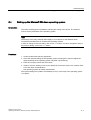
6.4
Setting up the Microsoft Windows operating system ................................................................. 6-7
6.5
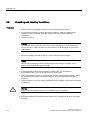
Installing applications and drivers, Touch-Base......................................................................... 6-8
6.6
Notes about new installation of Windows 2000 ....................................................................... 6-13
Operation and configuration.................................................................................................................... 7-1
7.1
7.1.1
Normal operation........................................................................................................................ 7-1
Switching the device on and off ................................................................................................. 7-1
7.2
7.2.1
7.2.2
7.2.3
7.2.4
7.2.5
7.2.6
7.2.7
Additional drivers and applications ............................................................................................ 7-4
Overview .................................................................................................................................... 7-4
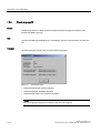
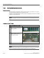
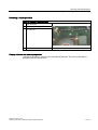
Setting the touch screen ............................................................................................................ 7-5
KeyTools .................................................................................................................................... 7-7
SystemGuard ............................................................................................................................. 7-8
TouchInput ................................................................................................................................. 7-9
CheckLanguageID ................................................................................................................... 7-10
Multilingual settings for the operating system .......................................................................... 7-11
Operating................................................................................................................................................ 8-1
8.1
Operator controls ....................................................................................................................... 8-1
8.2
8.2.1
8.2.2
8.2.3
Operator controls on key panels ................................................................................................ 8-3
Overview .................................................................................................................................... 8-3
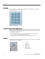
Keyboard .................................................................................................................................... 8-4
Labeling function keys and softkeys .......................................................................................... 8-7
8.3
8.3.1
8.3.2
Operator controls of the touch screen panels ............................................................................ 8-9
Overview .................................................................................................................................... 8-9
Touch screen ........................................................................................................................... 8-10
8.4
DVD-ROM drive ....................................................................................................................... 8-11
8.5
Transferring authorizations ...................................................................................................... 8-12
SIMATIC Panel PC 577
Operating Instructions, Release 04/2006, A5E00798484-01
Table of contents
9
10
11
12
13
Integration in TIA .................................................................................................................................... 9-1
9.1
Industrial communications ......................................................................................................... 9-1
9.2
PROFIBUS/MPI interface and WinAC card ............................................................................... 9-2
Servicing and maintenance................................................................................................................... 10-1
10.1
Servicing .................................................................................................................................. 10-1
10.2
10.2.1
10.2.2
10.2.3
10.2.4
10.2.5
10.2.5.1
10.2.5.2
10.2.6
10.2.6.1
10.2.6.2
10.2.7
10.2.8
10.2.9
10.2.10
10.2.11
Removing and installing hardware components ...................................................................... 10-3
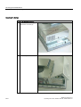
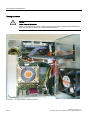
Repairs..................................................................................................................................... 10-3
Opening the device .................................................................................................................. 10-5
View of internal components with open device........................................................................ 10-9
Removing/installing memory modules ................................................................................... 10-10
PCI/WinAC cards ................................................................................................................... 10-12
Notes on the modules ............................................................................................................ 10-12
Installing expansion modules................................................................................................. 10-13
Drives ..................................................................................................................................... 10-17
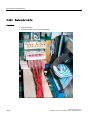
Removing and installing a DVD-ROM drive........................................................................... 10-17
Replacing the hard disk ......................................................................................................... 10-20
Changing processors and heat sinks..................................................................................... 10-24
Replacing the back-up battery ............................................................................................... 10-26
Removing/installing the power supply ................................................................................... 10-28
Separating the control unit from the computer unit................................................................ 10-30
Connecting an external monitor ............................................................................................. 10-37
10.3
10.3.1
10.3.2
10.3.3
10.3.4
10.3.5
Installing software .................................................................................................................. 10-38
Overview ................................................................................................................................ 10-38
Supplied software CDs / DVDs .............................................................................................. 10-40
Restoring the factory state of the software using the Restore DVD ...................................... 10-41
Factory state without operating system ................................................................................. 10-43
Installing individual drivers ..................................................................................................... 10-44
10.4
Maintenance and spare parts ................................................................................................ 10-45
Alarm, error and system messages ...................................................................................................... 11-1
11.1
BIOS error messages .............................................................................................................. 11-1
11.2
Motherboard error messages................................................................................................... 11-2
Troubleshooting and FAQs ................................................................................................................... 12-1
12.1
General problems .................................................................................................................... 12-1
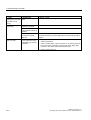
12.2
Problems when using modules of third-party manufacturers .................................................. 12-3
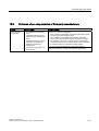
12.3
SystemGuard errors................................................................................................................. 12-4
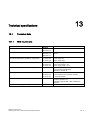
Technical specifications........................................................................................................................ 13-1
13.1
13.1.1
13.1.2
13.1.3
Technical data.......................................................................................................................... 13-1
EMC requirements ................................................................................................................... 13-1
General technical data ............................................................................................................. 13-2
Ambient and environmental conditions.................................................................................... 13-5
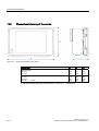
13.2
Dimensional drawing of the device .......................................................................................... 13-6
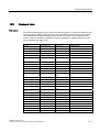
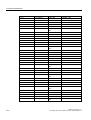
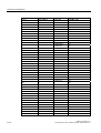
13.3
Keyboard table ......................................................................................................................... 13-7
SIMATIC Panel PC 577
Operating Instructions, Release 04/2006, A5E00798484-01
ix
Table of contents
14
A
Detailed descriptions ............................................................................................................................ 14-1
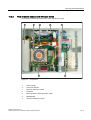
14.1
Overview of the Panel PC 577 motherboard ........................................................................... 14-1
14.2
Riser card ................................................................................................................................. 14-2
14.3
Touch sensor ........................................................................................................................... 14-3
14.4
14.4.1
14.4.2
System resources .................................................................................................................... 14-5
Currently allocated system resources...................................................................................... 14-5
Interrupt assignment ................................................................................................................ 14-6
14.5
14.5.1
14.5.2
BIOS setup ............................................................................................................................... 14-7
Starting BIOS setup ................................................................................................................. 14-7
BIOS setup default settings...................................................................................................... 14-8
Appendix.................................................................................................................................................A-1
A.1
A.1.1
A.1.2
A.1.3
A.1.4
Certificates and guidelines .........................................................................................................A-1
Guidelines and declarations.......................................................................................................A-1
Certificates and approvals..........................................................................................................A-3
ESD guideline ............................................................................................................................A-5
Electrostatic charging of individuals...........................................................................................A-7
A.2
Abbreviations .............................................................................................................................A-8
A.3
Glossary Definitions CU .............................................................................................................A-9
Index................................................................................................................................................ Index-1
Tables
Table 3-1
Dimensions for the mounting cut-out in mm ............................................................................ 3-12
Table 10-1
Switch settings for the various control units........................................................................... 10-36
x
SIMATIC Panel PC 577
Operating Instructions, Release 04/2006, A5E00798484-01
Safety instructions and general notes
1.1
1.1
1
Safety instructions
Warning
Emergencies
In the event of a device fault, remove the mains connector immediately. Inform the customer
service personnel responsible. Malfunctions can occur when the operator controls or power
cable are damaged or when liquids or foreign objects penetrate the device.
Caution
Please observe the safety instructions on the back of the cover sheet of this documentation.
You should not expand your device unless you have read the relevant safety instructions.
This device is compliant with the relevant safety measures to IEC, EN, VDE, UL, and CSA. If
you have questions about the validity of the installation in the planned environment, please
contact your service representative.
Repairs
Only authorized personnel are permitted to repair the device.
Warning
Unauthorized opening and improper repairs can cause considerable damage to property or
danger for the user.
SIMATIC Panel PC 577
Operating Instructions, Release 04/2006, A5E00798484-01
1-1
Safety instructions and general notes
1.1 Safety instructions
System expansions
Only install system expansion devices designed for this device. The installation of other
expansions can damage the system and violate the radio-interference suppression
regulations. Contact your technical support team or where you purchased your PC to find out
which system expansion devices may safely be installed.
Caution
If you install or exchange system expansions and damage your device, the warranty
becomes void.
Battery
This device is equipped with a Lithium battery. Batteries may only be replaced by qualified
personnel.
Caution
There is the risk of an explosion if the battery is not replaced as directed. Replace only with
the same type or with an equivalent type recommended by the manufacturer. Dispose of
used batteries in accordance with local regulations.
Warning
Risk of explosion and release of harmful substances!
Therefore, do not throw Lithium batteries into an open fire, do not solder or open the cell
body, do not short-circuit or reverse polarity, do not heat up above 100° C, dispose of in
accordance with regulations and protect against direct exposure to sunlight, moisture and
condensation.
1-2
SIMATIC Panel PC 577
Operating Instructions, Release 04/2006, A5E00798484-01
Safety instructions and general notes
1.1 Safety instructions
ESD guidelines
Modules containing electrostatic sensitive devices (ESDs) can be identified by the following
label:
Strictly follow the guidelines mentioned below when handling modules which are sensitive to
ESD:
• Always discharge your body´s static electricity before handling modules which are
sensitive to ESD (for example, by touching a grounded object).
• All devices and tools must be free of static charge.
• Always pull the mains connector and disconnect the battery before you install or remove
modules which are sensitive to ESD.
• Handle modules fitted with ESDs by their edges only.
• Do not touch any wiring posts or conductors on modules containing ESDs.
Warning
Following the results of a risk analysis, additional protection equipment on the machine or
the system is necessary to avoid endangering persons. With this, especially the
programming, configuration and wiring of the inserted I/O modules have to be executed, in
accordance with the safety performance (SIL, PL or Cat.) identified by the necessary risk
analysis. The intended use of the device has to be ensured.
The proper use of the device has to be verified with a function test on the system. This test
can detect programming, configuration and wiring errors. The test results have to be
documented and, if necessary, entered into the relevant documents that verify safety.
SIMATIC Panel PC 577
Operating Instructions, Release 04/2006, A5E00798484-01
1-3
Safety instructions and general notes
1.1 Safety instructions
Electrical connection
Warning
Disconnect the device from the mains before every intervention.
Do not touch power cables or data transmission cables during electrical storms and do not
connect any cables.
High frequency radiation
Caution
Unintentional operating situations
High frequency radiation, e.g. from cell phones, can cause unintentional operating situations
under some circumstances. For more details, consult the technical data in the "EMC
requirements" chapter.
1-4
SIMATIC Panel PC 577
Operating Instructions, Release 04/2006, A5E00798484-01
Safety instructions and general notes
1.2 General information, download "Panel PC"
1.2
1.2
General information, download "Panel PC"
Overview
Caution
The device is approved for operation in closed rooms only. The guarantee is void if this
stipulation is ignored.
Avoid extreme environmental operating conditions. Protect your device against dust,
moisture and heat. For additional information, refer to the Technical data.
Do not place the device in direct sunlight.
Transport
Unpack the device at its installation location.
Notice
Fitting the hard disk transport lock again
Transport the device only in the original packaging. Fit the hard disk transport lock again for
this purpose: Switch off the device and place it in the operating position. Screw in the knurled
screws as far as the stop.
Notice
Adhere to these stipulations each time the device is transported, otherwise the guarantee is
void.
SIMATIC Panel PC 577
Operating Instructions, Release 04/2006, A5E00798484-01
1-5
Safety instructions and general notes
1.2 General information, download "Panel PC"
Caution
Condensation
When transporting the device in low temperatures, ensure that no moisture gets on or into
the device. This also applies if the device is subjected to extreme changes in temperature.
Commissioning
Allow the device to slowly adjust to room temperature before commissioning the device. Do
no place the device near direct heat radiation. If moisture condensation occurs, wait at least
about 12 hours before you switch on the device.
Vibration
DVD drives are sensitive to vibration. Prohibited vibration during operation may result in loss
of data or damage to the drive or data medium.
Before transporting the device, wait at least 20 seconds to allow the drive to stop completely.
Tools & downloads
Please check regularly whether updates and hotfixes are available for download to your
device.
Downloads are available on the Internet at "http://www.siemens.com/asis" under "Support".
Click on "Tools & Demosoftware" on "Overview Panel PCs". Using the global search
function, you can then also search for any downloads you require.
Processor and CD-ROM drive
Caution
Danger of overheating the processor!
Do not activate the "Silent mode" option in the BIOS setup.
Notice
A CD-ROM drive should only be operated in a mechanically undisturbed environment
without vibrations and shock.
1-6
SIMATIC Panel PC 577
Operating Instructions, Release 04/2006, A5E00798484-01
Safety instructions and general notes
1.2 General information, download "Panel PC"
Safety-relevant applications
Warning
Maloperation
Do not perform safety-relevant functions of the user software with the touch screen.
Chemical resistance
Caution
Adhere to the information regarding chemical resistance. Please refer to the "Tools &
Demosoftware" Internet site for more information. Enter "Chemical resistance" as the search
term. The available articles are displayed.
Sources of light
Notice
Position the screen so that it is not subject to direct sunlight or other strong sources of light.
Defective pixels in the display
At present, the manufacturing process of modern displays does not guarantee that all pixels
of the display will be perfect. A small number of defective pixels in the display is therefore
unavoidable. This does not present a functional problem as long as the defective pixels are
not bunched in one location.
Refer to the "Technical data" section for more information.
SIMATIC Panel PC 577
Operating Instructions, Release 04/2006, A5E00798484-01
1-7
Safety instructions and general notes
1.2 General information, download "Panel PC"
Burn-in effect on TFT displays
A permanent picture with bright images can lead to a burn-in effect on the TFT LCD.
If a screen saver is activated, please observe the following:
• The liquid crystals in screen savers which actuate active black when the backlighting is
on, e.g. flying stars "starfield simulation," renew themselves. Pay attention to the length of
time the backlighting is activated.
• The following applies to screen savers which turn off the backlighting: Each time the
backlighting is turned on, its life is reduced by 50 minutes.
Consider the following carefully:
• Screensaver
• Switch off the backlighting regularly
• Permanent display of the customer application
1-8
SIMATIC Panel PC 577
Operating Instructions, Release 04/2006, A5E00798484-01
Description
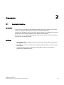
2.1
2.1
2
Application features
Introduction
The Panel PC 577 provides a high standard of quality based on the protection type of the
control unit, high-level EMC and CE certification for industrial application.
The device is designed for 24 hour operation. Further information is available in the section
"Ambient and environmental conditions of the "Technical data" chapter.
The Panel PC 577 is scalable beginning with the processor type and the memory modules
all the way to the operating system.
Interfaces
• The integrated Ethernet interface ensures communication with the office world and the
management level.
• PC peripherals can be connected via the integrated USB interfaces at the rear and front
of the device.
• Connection to the process is made with communication cards and PC expansion
modules in the available PC slots.
SIMATIC Panel PC 577
Operating Instructions, Release 04/2006, A5E00798484-01
2-1
Description
2.2 Design
2.2
2.2
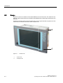
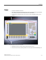
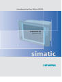
Design
The device serves as a base for PC-based HMI devices, the Panel PCs. The Panel PC 577
fulfills the basic requirements for industrial compatibility and provides high performance at a
low price.
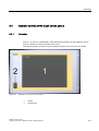
The device consists of the control unit with a key or touch panel and the computer unit. The
control unit is screwed to the back of the computer unit.
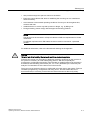
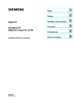
Figure 2-1
2-2
Panel PC 577
1
Control unit
2
Computer unit
SIMATIC Panel PC 577
Operating Instructions, Release 04/2006, A5E00798484-01
Description
2.3 Technical features
2.3
2.3
Technical features
General features
Processor
- Intel® Pentium 4 2.4 GHz
- Intel® Celeron 2.0 GHz
Chipset
Intel 865G
Main memory
256 MB = 2 x 128 MB SDRAM or
1 x 256 MB SDRAM
512 MB = 2 x 256 MB SDRAM
4 slots, expandable to 4 GB maximum
Slots for add-ons
•
•
Device variants
The device is available with different control
units which are distinguished by the size of the
display and by a membrane keyboard or touch
screen.
Uppermost slot is suitable for WinAC Slot
module
2 x PCI 175 mm long (below)
Keyboard variants
• 12"/15" TFT technology
• Color display with backlighting
• Membrane keyboard with alphanumeric keys,
numeric keys, cursor keys and control keys
• Function keys and softkeys
• Integrated mouse
• Softkeys, <Shift> und <ACK>
• Front-mounted USB 2.0 interface for
connecting external I/O modules
Touch screen variants
• 12''/15''/19'' TFT technology
• Color display with backlighting
• Front-mounted USB 2.0 interface for
connecting external I/O modules
Graphics
On-board graphics (865G chipset)
12'': 800 x 600, 60 Hz
15'': 1024 x 768, 60 Hz
19'': 1280 x 1024, 60 Hz
Power supply
110/230 V AC, 350 W; variable voltage with shortterm buffering against power failure at maximum
16 ms
Drives optional
CD-ROM drive
Hard disks
≥ 40 GB HDD small, 1x 2.5"
Operating system, optional
Preinstalled, also installed on the Restore CD
- Windows 2000 Professional MUI*
- Windows XP Professional MUI*
*MUI: Multi-language user interface; German,
English, French, Italian, Spanish, Japanese,
Korean, Chinese simplified and Chinese
traditional
SIMATIC Panel PC 577
Operating Instructions, Release 04/2006, A5E00798484-01
2-3
Description
2.3 Technical features
Interfaces
Installed via expansion cards: PROFIBUS / MPI
CP 5611-compatible
(not included in the scope of supply)
Ethernet
LAN 10/100/1000 Mbps
USB
4x USB 2.0 high current, external
2x USB 2.0 high current available, internal
via male connector
Serial interfaces
COM1 V.24
Parallel interfaces
LPT1
Keyboard
PS/2
Mouse
PS/2
1x USB 2.0 high current, front mounted
Accessories not supplied with the device package
SIMATIC PC
Image Creator SW
Film for protecting the touch screen panel
against dirt and scratches
for the 12" touch screen variant
for the 15" touch screen variant
for the 19" touch screen variant
2-4
Software for local data backup
6AV7671-2BA00-0AA0
6AV7671-4BA00-0AA0
6AV7672-1CE00-0AA0
Labeling strips
for 12" keyboard variant
for 15" keyboard variant
6AV7672-0DA00-0AA0
Screw fixing elements
for 19'' touch screen variant
6AV7672-8KE00-0AA0
The labeling strips and printing templates can be
obtained from the Internet address mentioned in
the preface.
SIMATIC Panel PC 577
Operating Instructions, Release 04/2006, A5E00798484-01
Description
2.3 Technical features
SIMATIC Panel PC 577
Operating Instructions, Release 04/2006, A5E00798484-01
2-5
Description
2.3 Technical features
2-6
SIMATIC Panel PC 577
Operating Instructions, Release 04/2006, A5E00798484-01
Planning use
3.1
3.1
3
Overview
Introduction
This section describes the first steps after unpacking, the permitted mounting positions and
the fixation. This section describes the necessary considerations for EMC.
Field of application
The Panel PC is an industry-standard PC platform for demanding tasks in the field of PCbased automation. The Panel PC is designed for on-site use on the machine, installed for
example in:
• Control cabinets
• Swivel arms
• In consoles
Note
In the following, the term "control cabinet" also refers to rack, mounting rack, switchboard,
operator panel and console. The term "device" represents the Panel PC and its variants.
SIMATIC Panel PC 577
Operating Instructions, Release 04/2006, A5E00798484-01
3-1
Planning use
3.2 Unpacking and checking the delivery
3.2
3.2
Unpacking and checking the delivery
Procedure
1. Please check the packaging material for transport damage upon delivery.
2. If any transport damage is present at the time of delivery, lodge a complaint at the
shipping company in charge. Have the shipper confirm the transport damage
immediately.
3. Unpack the device.
Caution
Do not lie the device on its back. This will avoid any damage to an optical drive which
may be present. Lie the front side on a soft surface to avoid damaging the front panel
USB interface.
4. Keep the packaging material in case you have to transport the unit again.
Notice
The packaging protects the device during transport and storage. Therefore, never
dispose of the original packaging material!
5. Please keep the enclosed documentation in a safe place. You will need the
documentation when you start up the device for the first time.
6. Check the package contents for completeness and any visible transport damage. Check
for completeness using the "Contents of Delivery" list in the Operating Instructions
(compact).
7. Notify the delivery service in charge immediately if the packages contents are incomplete
or damaged.
Warning
Make sure that a damaged device is not installed or put into operation.
8. Note the identification information as described in the "Operating Instructions (compact)"
document.
3-2
SIMATIC Panel PC 577
Operating Instructions, Release 04/2006, A5E00798484-01
Planning use
3.2 Unpacking and checking the delivery
Warning
Risk of damage
Do not transport the device when it is mounted. During transport, use the hard disk
transport lock (if present).
The device is approved for use with the following operating systems:
Approvals
• Windows 2000 Professional Multi-Language SP4 and higher, German, English, French,
Italian, Spanish, Japanese, Korean, Chinese Simplified and Chinese Traditional
• Windows XP Professional Multi-Language, German, English, French, Italian, Spanish,
Japanese, Korean, Chinese Simplified and Chinese Traditional
Windows XP Professional is only approved as of Service Pack 2.
The operating system is provided with the Windows function modes "Hibernate" and
"Standby" deactivated when shutting down the operating system and with "Fast User
Switch" (Windows XP Professional) deactivated.
SIMATIC Panel PC 577
Operating Instructions, Release 04/2006, A5E00798484-01
3-3
Planning use
3.3 Make note of identification data
3.3
3.3
Make note of identification data
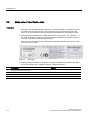
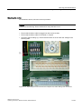
Procedure
1. Write down the Microsoft Windows product key of the Certificate of Authenticity COA in
the table at the end of this section. The product key can be found on the back of the
device. You will need the product key during the reinstallation of the operating system.
2. Write down the manufacturer's number SVP and the order number , e.g. "6AV782...", in
the table. If repairs are necessary, the device can be identified by the service center on
the basis of the SVP number and order number.
Both numbers can be found on the rating plate attached to the side of the device where
the power unit is located.
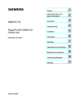
Figure 3-1
Rating plate
3. Enter the Ethernet address of the device: The Ethernet address is located in the "Main"
menu of the BIOS setup, "Hardware Options > Ethernet Address."
Identification
1
Microsoft Windows Product Key
2
SVP number
3
Order number
10
Ethernet address (MAC address)
3-4
Number
SIMATIC Panel PC 577
Operating Instructions, Release 04/2006, A5E00798484-01
Planning use
3.4 EMC directive
3.4
3.4
EMC directive
Electromagnetic compatibility
The device fulfills the requirements of the EMC law of the Federal Republic of Germany as
well as the EMC directive of the Single European Market.
The device is designed as a built-in model with front-sided IP65 degree of protection. Ensure
compliance with the EN 61000-4-2 standard by installing the device in grounded metal
cabinets, e.g. 8 MC cabinets, Siemens catalog NV21.
Note
For additional information about EMC requirements, refer to the Technical data section.
Installing the device according to EMC directive
Basics for interference-free operation:
• Install the controller according to EMC directive
• Use interference-immune cable
Note
The instructions "Guidelines for the assembly of interference-immune programmable logic
controllers" with the article ID 1064706 and the manual "PROFIBUS networks" with the
article ID 1971286, which also applies to the installation of the device, is located on the
"Documentation and Drivers" CD.
SIMATIC Panel PC 577
Operating Instructions, Release 04/2006, A5E00798484-01
3-5
Planning use
3.5 Mounting positions and fastening
3.5
3.5.1
3.5
Mounting positions and fastening
Installation instructions
Before mounting the device, read the following general notes relating to installation.
Warning
Dangerous Voltage
Isolate the power supply to the control cabinet before opening it. Ensure that the power to
the control cabinet cannot be turned on accidentally.
Caution
The device is approved for operation in closed rooms only.
• Ensure that the grounding outlet of the building installation is easily accessible and that
there is a mains disconnect switch in control cabinet installations.
• Position the screen in an ergonomic position favorable to the user. Choose a suitable
mounting height.
• Position the screen so that it is not subject to direct sunlight or other strong sources of
light.
• DVD drives are susceptible to shock. Shocks during operation can lead to the loss of data
or damage to the drive or data carrier. Burners and DVDs are not suitable for continous
operation.
• Applies to devices which are installed in swivel arm housings: Avoid rapid or jerky
movements of the swivel arm during operation. The ensuing forces could lead to possible
irreversible damage of the hard disk.
• Provide adequate volume in the control cabinet for air circulation and heat transport.
Keep at least 10 cm distance between the device and control cabinet.
• Do not allow the maximum air intake temperature to exceed 45° C. Decisive is the
temperature measured at a distance of 10 cm from an air intake. The maximum air intake
temperature must be accounted for especially when sizing closed control cabinets.
• Position the device so that the air vents of the housing are not covered up following
mounting.
• Ensure there is enough free space in the control cabinet to allow the sheet metal cover to
be removed. You will otherwise have to remove the device from the control cabinet or
swivel arm when replacing the memory or the battery.
3-6
SIMATIC Panel PC 577
Operating Instructions, Release 04/2006, A5E00798484-01
Planning use
3.5 Mounting positions and fastening
• Also provide enough free space to add on to the device.
• Equip the control cabinet with struts for stabilizing the mounting cut-out. Install struts
where necessary.
• Avoid extreme environmental operating conditions. Protect your device against dust,
moisture and heat.
• Install the device in such a way that it poses no danger, e.g. by falling over.
• During assembly, please comply with the approved mounting positions.
Notice
The device must be mounted in a fireproof cabinet to fulfill the requirements for UL508
certification.
To fulfill the requirements for EN 60950, the device must be mounted in a permitted
position.
For additional information, refer to the dimensional drawings in the appendix.
Warning
Function test while installing the device in machines or execute systems
Following the results of a risk analysis, additional protection equipment on the machine or
the system is necessary to avoid endangering persons. With this, especially the
programming, configuration and wiring of the inserted I/O modules have to be executed, in
accordance with the safety performance (SIL, PL or Cat.) identified by the necessary risk
analysis. The intended use of the device has to be ensured.
The proper use of the device has to be verified with a function test on the system. This test
can detect programming, configuration and wiring errors. The test results have to be
documented and, if necessary, entered into the relevant documents that verify safety.
SIMATIC Panel PC 577
Operating Instructions, Release 04/2006, A5E00798484-01
3-7
Planning use
3.5 Mounting positions and fastening
3.5.2
Permitted mounting positions
Approval
Only certain mounting positions are approved for the device.
Figure 3-2
Permitted mounting position
The device can be mounted in a vertical position with deviations between +5° and -5° in the
given directions.
3.5.3
Mounting type
The control unit is secured in the mounting cut-out either with clamps or screws.
Notice
Securing with screws is not possible with the 12" touch screen variant.
For securing the 19'' touch screen variant with screws, you will need the accessory with
MLFB No. 6AV7672-8KE00-0AA0
Select the type of mounting suitable to your requirements for the degree of protection.
3-8
SIMATIC Panel PC 577
Operating Instructions, Release 04/2006, A5E00798484-01
Planning use
3.5 Mounting positions and fastening
3.5.4
Degree of protection
Principle
The degree of protection provided at the front is assured when the mounting seal lies
completely against the mounting cut-out.
Caution
Please ensure that the material strength at the mounting cut-out is a maximum of 6 mm.
Please follow the specifications for the dimensions in the "Mounting cut-out" section.
The degrees of protection are only guaranteed when the following is observed:
• The material strength at the mounting cut-out is at least 2 mm.
• The surface plane deviation of the mounting cut-out in relation to the external dimensions
of the control unit amounts to ≤ 0.5 mm when the control unit is mounted.
IP65 degree of protection and NEMA4
The IP65 degree of protection and NEMA4 is only provided for clamp mounting together with
a ring seal.
IP54 degree of protection
This degree of protection is assured when fixed using screws and the mounting components
for 19" rack accessories.
Note
For screw fixing of the 19" touch panel front, a backing plate is available as an accessory.
For further information, see "http://mall.ad.siemens.com/".
SIMATIC Panel PC 577
Operating Instructions, Release 04/2006, A5E00798484-01
3-9
Planning use
3.6 Mounting cut-out
3.6
3.6.1
3.6
Mounting cut-out
Selecting and creating the mounting cut-out
Requirement
The degree of protection suitable to the field of application and thereby the mounting method
have been selected.
Procedure
1. Follow the installation instructions.
2. Select a location suitable for installation, taking into account the installation instructions
and the chosen mounting position.
3. On the basis of the dimensional drawings, check whether the required screw and
pressure points on the rear and the hatched seal area are easily accessible after the
completion of the mounting cut-out. Otherwise the mounting cut-out is useless.
4. Complete the mounting cut-out in accordance with the dimensions. You can also obtain
these dimensions from the mounting template supplied with the device.
3-10
SIMATIC Panel PC 577
Operating Instructions, Release 04/2006, A5E00798484-01
Planning use
3.6 Mounting cut-out
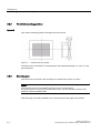
3.6.2
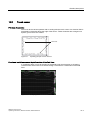
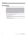
Dimensions
The following illustration shows the dimensions for the mounting cut-out. You can also obtain
these dimensions from the mounting template supplied with the device.
$
/
$
/
/
/
6
6
/
/
6
/
6 6
/
/
/
/
/
6
6
/
PP
/
Figure 3-3
Drill holes for the screws and pressure points for the clamp screws
(1)
Drill hole for screw attachment
(4)
Clamp
(2)
Pressure points for clamp
(5)
RZ 120 in the seal area
(3)
Setscrews
(6)
Seal area
SIMATIC Panel PC 577
Operating Instructions, Release 04/2006, A5E00798484-01
3-11
Planning use
3.6 Mounting cut-out
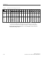
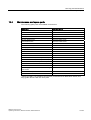
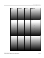
Table 3-1
Dimensions for the mounting cut-out in mm
Control
units
L1
L2
L3 1) L4 1) L5
L6 2) L7
L8 2)
L9 2) A1
A2
S1
S2
S3
S4
S53) S63) S73)
Tolerance
+1
+1
±0.2 ±0.2 ±0.5 ±0.5 ±0.
5
±0.5
+1
±1
±1
±1
±1
±1
±1
±1
±1
±1
12" TFT
450
290
465
235
112
—
—
—
—
16
10
78
78
78
78
56
—
—
15" TFT
450
321
465
279
112
186
135 25
165
16
17
51
51
51
51
56
—
—
Touch
screen
panels
368
290
—
—
112
—
—
—
—
16
10
19
35
35
35
56
—
—
450
290
465
235
112
—
—
—
—
16
10
81
81
81
81
56
—
450
380
465
235
112
—
—
—
—
16
10
46
46
46
46
—
33
—
33
2)
Key
panels
12" TFT
15" TFT
19" TFT
1)
M6 thread or drill holes with a diameter of 7 mm
2)
Cut-outs for the shafts of the insert strips are only necessary for 15" key panels.
3)
Only for 19" touch panels are two clamps necessary for vertically securing clamps.
More information about device dimensions, e.g. mounting depth, can be found in the
"Dimensional drawings" section.
3-12
SIMATIC Panel PC 577
Operating Instructions, Release 04/2006, A5E00798484-01
4
Installation
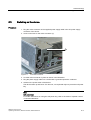
4.1
4.1
Securing with clamps
Scope
Skip this step if you have selected "screw mounting."
Note
The 12" touch screen variant can only be fixed in place using clamps.
Requirement
• The mounting cut-out has been completed.
• Clamps are readily available in the accessories. Clamps and setscrews are included in
the contents of delivery.
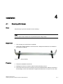
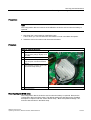
Figure 4-1
Clamp assembly
Procedure
1. Follow the installation instructions.
2. Working from the front, insert the device into the mounting cut-out.
3. Secure the control unit in the mounting cut-out from behind with the clamps, as shown in
the mounting cut-out in the dimensions. Tighten the setscrews to a torque of 0.4-0.5 Nm.
SIMATIC Panel PC 577
Operating Instructions, Release 04/2006, A5E00798484-01
4-1
Installation
4.2 Securing with screws
4.2
4.2
Securing with screws
Scope
Skip this step if you have selected "clamp mounting."
Notice
Securing with screws is not possible with the 12" touch screen variant.
For securing the 19'' touch screen variant with screws, you will need the accessory with
MLFB No. 6AV7672-8KE00-0AA0
Requirement
The mounting cut-out has been completed.
4-2
SIMATIC Panel PC 577
Operating Instructions, Release 04/2006, A5E00798484-01
Installation
4.2 Securing with screws
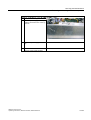
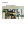
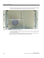
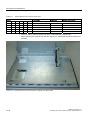
Procedure
1. Follow the installation instructions.
2. Drill suitable holes at the prepared mounting cut-out in accordance with the specifications
for L4 and L5, as shown in the mounting cut-out in the dimensions.
3. Carefully drill the respective holes in the control unit at the designated location (1) from
the rear.
Figure 4-2
Designated location for holes on the control unit
4. Working from the front, insert the device into the mounting cut-out.
5. Secure the control unit by inserting suitable screws through the holes and attaching nuts.
SIMATIC Panel PC 577
Operating Instructions, Release 04/2006, A5E00798484-01
4-3
Installation
4.3 Dimensions
4.3
4.3
Dimensions
The mounting depth increases by 28 mm when a DVD-ROM drive is installed in the device.
Refer to the dimensional drawings in the "Technical specifications" section for the exact
measurements.
4-4
SIMATIC Panel PC 577
Operating Instructions, Release 04/2006, A5E00798484-01
Connecting
5.1
5.1
5
Overview
Introduction
Once you have mounted the device, connect it.
Warning
Do not touch power cables or data transmission cables during electrical storms and do not
connect any cables.
Unplug the mains connector from the socket to be sure the electricity is disconnected.
Caution
Connection sequence
Follow the described sequence when connecting the device to avoid damaging it.
Commissioning
Allow the device to adjust to the room temperature before connecting the device. Do no
place the device near direct heat radiation. If moisture condensation occurs, wait at least
about 12 hours before you switch on the device.
Risk of data loss!
Do not disconnect the power supply when the device is in operation. Disconnect the power
only after the device has been correctly shut down.
Requirement
• The device has been installed in conformity with the EMC directive
• The device has been installed according to the information provided in these operating
instructions.
SIMATIC Panel PC 577
Operating Instructions, Release 04/2006, A5E00798484-01
5-1
Connecting
5.1 Overview
Procedure
1. Connect the equipotential bonding.
2. Connect peripherals:
– Connect an external monitor if desired.
– Connect the PS/2 mouse.
– Connect the PS/2 keyboard.
– Connect a USB device such as a USB mouse if desired.
– Connect a printer.
3. Connect the power supply.
5-2
SIMATIC Panel PC 577
Operating Instructions, Release 04/2006, A5E00798484-01
Connecting
5.2 Interfaces
5.2
5.2.1
5.2
Interfaces
Front interfaces
Introduction
A USB interface is located on the front side. For more information, please refer to the
chapter "Operation." Attach an external keyboard or an external mouse, for example, to the
USB interface. The front-side USB interface supports the standard USB 2.0.
Caution
Wait at least 10 seconds between the unplugging and replugging of USB devices. This also
applies in particular to touch control in control units with touch screen panels.
Notice
When the cover over the USB interface is opened in order to connect a USB component, the
degree of protection for the device is no longer guaranteed.
When using standard USB peripherals, please bear in mind that their EMC immunity level is
frequently designed for office applications only. These devices are adequate for
commissioning and servicing purposes. However, only industry-standard devices are
allowed for industrial operation.
The peripherals are developed and marketed by individual vendors. The respective
manufacturers offer support for the peripherals. Moreover, the terms of liability of the
individual vendors or suppliers apply here.
SIMATIC Panel PC 577
Operating Instructions, Release 04/2006, A5E00798484-01
5-3
Connecting
5.2 Interfaces
5.2.2
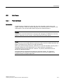
Rear interfaces
Interfaces
Arrangement of the interfaces
5-4
Item
Name
Description
(1)
KEYBOARD
Connection for a PS/2 keyboard
(2)
Mouse
Connection for a PS/2 mouse
(3)
USB 2.0
Connection for USB devices
(4)
COM 1
Serial interface, 9-pin Sub-D
connector
(5)
LPT 1
Parallel interface, 25-pin sub D
socket
(6)
VGA
VGA connection
(7)
USB 2.0
Connection for USB devices
(8)
Ethernet
RJ 45 Ethernet connection
10/100/1000 Mbps
SIMATIC Panel PC 577
Operating Instructions, Release 04/2006, A5E00798484-01
Connecting
5.2 Interfaces
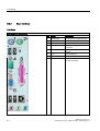
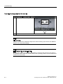
Power supply
Position of the IEC power connector
Description
IEC power connector (2) for the AC power
supply to the device. The maximum
permitted power supply range is 120 V AC
to 230 V AC.
On / Off switch (1)
Note
You can also switch on the device using the soft power key. Refer to the "Operator controls"
chapter for more information.
SIMATIC Panel PC 577
Operating Instructions, Release 04/2006, A5E00798484-01
5-5
Connecting
5.3 Connecting peripherals
5.3
5.3.1
5.3
Connecting peripherals
Overview
When connecting the device for the first time, connect a PS/2 keyboard and PS/2 mouse.
Connect any required USB components such as a USB hub.
Caution
Disconnect the device from the power supply before connecting peripherals. This does not
apply to connecting and disconnecting USB devices.
Connect only I/O modules approved for industrial applications according to EN 61000-62:2001. Use shielded cables and metal connectors to connect peripherals. Otherwise, the
specified standards and specifications declared by Siemens AG are no longer valid. Secure
the plugs of the interface cables to the device housing with screws. This improves the
electrical shielding.
Mouse
Connect a PS/2 or USB mouse.
5.3.2
Connecting a monitor
The front panel is activated as the display by default when the operating system starts. An
external monitor connected to the VGA port is therefore deactivated.
Learn how to activate an external monitor by reading the section "Installing and removing
hardware components" in the "Service and maintenance" chapter.
5-6
SIMATIC Panel PC 577
Operating Instructions, Release 04/2006, A5E00798484-01
Connecting
5.3 Connecting peripherals
5.3.3
USB
Introduction
Commercially available USB peripherals can be easily and flexibly connected via the USB
interface. For example, you can connect an external USB keyboard and a USB mouse. If the
USB keyboard has a USB interface, you can connect other USB peripherals, such as a USB
mouse, directly to the keyboard.
USB interface
There are several types of USB peripherals:
• Low power devices: maximum 100 mA power consumption, e.g. mouse and keyboard
• High power devices maximum 500 mA power consumption, e.g. hard disk and floppy
drive
Note
The general USB specifications apply to the USB interfaces on the computer unit.
The USB interface on the front panel has been approved for a maximum of one additional
USB hub.
Using USB peripherals
Notice
When installing a USB device for the first time, make sure you have the required device
driver.
Before removing an intelligent USB device, deactivate the device in the operating system
using the dialog "Unplug or Eject Hardware". For additional information, refer to the
documentation for the operating system.
SIMATIC Panel PC 577
Operating Instructions, Release 04/2006, A5E00798484-01
5-7
Connecting
5.3 Connecting peripherals
Connecting USB devices
Caution
Wait at least 10 seconds between removal and reconnection of USB devices. This also
applies to control units with touch screens, especially for touch operation.
Notice
When using standard USB peripherals, please bear in mind that their EMC immunity level is
frequently designed for office applications only. These devices are adequate for
commissioning and servicing purposes. However, only industry-standard devices are
allowed for industrial operation.
The peripherals are developed and marketed by individual vendors. The respective
manufacturers offer support for the peripherals. Moreover, the terms of liability of the
individual vendors or suppliers apply here. More information about connecting USB devices
is available in the "Commissioning" section.
Procedure
1. Insert the USB cable into one of the USB interfaces. The device is automatically detected
by the Plug and Play operating system. The operating system may prompt you to install a
driver when necessary.
5-8
SIMATIC Panel PC 577
Operating Instructions, Release 04/2006, A5E00798484-01
Connecting
5.4 Connecting the power supply
5.4
5.4
Connecting the power supply
Principle
The device can be optionally operated on 110 or 230 V AC systems. The device features an
automatic voltage switch and a power switch.
Caution
Do not touch power cables or data transmission cables during electrical storms and do not
connect any cables.
Unplug the mains connector from the socket to be sure the electricity is disconnected.
The device features a safety-certified power cable. Connect the device only to a grounding
outlet. Operate the device only on grounded power cables and not on impedance grounding
systems such as IT systems.
Make sure that the local supply voltage complies with the permissible rated voltage for the
device.
Warning
Select an adequately large cable diameter so that the device is not damaged by the cable
during a short circuit.
Localized information
Outside of the USA and Canada, 230 V AC power supply:
If you do not use the safety-certified power cable, use a flexible cable with the following
characteristics:
• At least 18 AWG conductor cross-section
• Grounding plug 15 A, 250 V
Notice
Ensure that the cable set conforms to the respective national safety regulations and is
appropriately labeled.
SIMATIC Panel PC 577
Operating Instructions, Release 04/2006, A5E00798484-01
5-9
Connecting
5.4 Connecting the power supply
For USA and Canada:
A UL-listed power supply cable must be used in the United States and Canada.
110V power supply
Use a flexible cable with the following characteristics:
• UL approval
• Type SJT with three conductors
• At least 18 AWG conductor cross-section
• Maximum 4.5 m length
• Parallel grounding plug 15 A, min. 125 V
230V power supply
Use a flexible cable with the following characteristics:
• UL approval
• Type SJT with three conductors
• At least 18 AWG conductor cross-section
• Maximum 4.5 m length
• Tandem grounding plug 15 A, min. 250 V
Procedure
1. Insert the supplied power cable into the AC/DC power socket of the device.
2. Lock the power plug with the interlocking device supplied in the package. This will
prevent unintentional detachment of the IEC power connector on the device.
5-10
SIMATIC Panel PC 577
Operating Instructions, Release 04/2006, A5E00798484-01
Connecting
5.5 Uninterruptible AC power supplies
5.5
5.5
Uninterruptible AC power supplies
Introduction
This chapter describes the considerations involved in using an uninterruptible AC power
supply (AC UPS) for the Panel PC.
Due to legal regulations related to reducing reactive-power consumption in public and private
electrical networks, all AC voltage supplies in Panel PCs feature a power factor correction
(PFC) circuit. Technically, there is passive PFC and active PFC.
Active PFC
All Panel PC 87x, Panel PC 577 and Panel PC 677 feature an active PFC. Active PFC
requires almost perfect sinusoidal input voltage.
Caution
Uninterruptible AC power supplies (AC UPS) with non-sinusoidal wave form damage the
power supply unit of Panel PCs with active PFC.
Make that the AC UPS supplies a sinusoidal output voltage in normal and battery mode for
use on a Panel PC with active PFC.
Selection criteria for an uninterruptible power supply
Uninterruptible power supplies with sinusoidal output voltage in normal and battery mode are
classified as "VFI-SS-…" or "VI-SS-…".
UPS characteristics are described and classified in EN 50091-3 and IEC 62040-3.
Note
More information is available on the Internet at "www.ad.siemens.de" under "Products &
Solutions." Click on "Service & Support" under "Services" and search for the article ID
"17241008" on the "Product Support" page. At the end of the article there is a link to the
document, "UPS Classification Based On Operational Performance".
SIMATIC Panel PC 577
Operating Instructions, Release 04/2006, A5E00798484-01
5-11
Connecting
5.6 Connecting the equipotential bonding
5.6
5.6
Connecting the equipotential bonding
A low-resistance ground connection ensures that interference signals generated by external
power supply cables, signal cables or cables to the I/O modules are safely discharged to
ground.
The equipotential bonding connection of the device is located at the connection elements of
the computer unit and is identified by the following symbol:
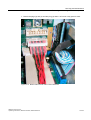
Figure 5-1
Equipotential bonding
Connecting the equipotential bonding
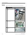
Required tool for equipotential bonding terminal: TORX T20 screwdriver
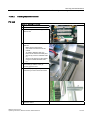
Steps for connecting the equipotential bonding
1
5-12
Connect the equipotential bonding connection
(M4 thread) on the device (1) (large surface,
large-area contact) with the central grounding
point of the control cabinet.
The minimum conductor cross-section may not
amount to less than 5 mm2.
SIMATIC Panel PC 577
Operating Instructions, Release 04/2006, A5E00798484-01
Connecting
5.6 Connecting the equipotential bonding
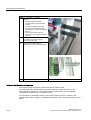
Avoiding differences in potential
Differences in potential arise between separated system parts, which in some cases lead to
high equalization currents. This situation may arise if the cable shielding is terminated at
both ends and grounded at different system parts. Potential differences can be caused, for
example, by different power inputs.
Reduce the differences in potential by laying the equipotential bonding cables in such a way
that the affected electronic components function properly. Observe the following guidelines
when setting up equipotential bonding:
• When two system parts are connected by means of a shielded signal cable, and their
shields are both connected to the ground or protective conductor, the following must be
observed: The impedance of the additional equipotential bonding cable amounts to 10%
of the shield impedance, at the most.
• Ensure that the equipotential bonding cable cross-section is selected to accommodate
the maximum equalization current. The equipotential bonding conductor cross-section
that has proven best in practice is 16 mm2.
• Use equipotential bonding conductors made of copper or galvanized steel. Connect the
cables to the ground or protective conductor over a wide area. Protect the ground or
protective conductor from corrosion.
• Lay the equipotential bonding cable in such a way that the area between the equipotential
bonding cable and signal cables is as small as possible.
SIMATIC Panel PC 577
Operating Instructions, Release 04/2006, A5E00798484-01
5-13
Connecting
5.6 Connecting the equipotential bonding
5-14
SIMATIC Panel PC 577
Operating Instructions, Release 04/2006, A5E00798484-01
Connecting
5.6 Connecting the equipotential bonding
SIMATIC Panel PC 577
Operating Instructions, Release 04/2006, A5E00798484-01
5-15
Commissioning
6.1
6.1
6
Removing the transport lock for the hard disk
Note
Not every device has a hard disk transport lock.
To enhance the ruggedness of the SIMATIC Panel PC 577 during shipping, the device is
fitted with a transport lock for the hard disk. This comprises two knurled screws that clamp
the hard disk to prevent undesirable vibrations. The hard disk transport lock is located on the
top of the SIMATIC Panel PC 577 and is marked with an adhesive label. When shipped, the
transport lock is locked. Before you switch on the device for the first time, you must remove
the transport lock for the hard disk.
SIMATIC Panel PC 577
Operating Instructions, Release 04/2006, A5E00798484-01
6-1
Commissioning
6.1 Removing the transport lock for the hard disk
Removing the transport lock for the hard disk
Procedure for removing the transport lock for the hard disk
(1)
Unscrew 2 knurled screws (1) by hand
+DUG'LVN7UDQVSRUWVLFKHUXQJ
ELWWHYRUGHU,QEHWULHEQDKPH
HQWIHUQHQ[5¦QGHOVFKUDXEHQ
3OHDVHUHPRYHWKHKDUGGLVN
WUDQVSRUWORFNEHIRUHRSHUDWLQJ
(2)
Screw the knurled screws into the nuts on the rear of the device for safe-keeping.
Notice
Risk of damage
If you do not remove the hard disk transport lock before starting up the device, the SIMATIC
Panel PC 577 may suffer damage.
Notice
Fitting the hard disk transport lock again
Transport the device only in the original packaging. Fit the hard disk transport lock again for
this purpose: Switch off the device and place it in the operating position. Screw in the knurled
screws as far as the stop.
6-2
SIMATIC Panel PC 577
Operating Instructions, Release 04/2006, A5E00798484-01
Commissioning
6.2 Overview
6.2
6.2
Overview
Checklist
Before starting up the device for the first time, go through the following checklist:
• Have you taken into account the proper ambient and environmental conditions for the
device and the connected I/O modules, as described in the technical information?
• Have you removed the hard disk transport lock?
• Have you learned how to connect the equipotential bonding?
• Have you learned how to connect the power supply?
• Read over this information in the respective "Connecting" chapter of the operating
instructions. Please follow all guidelines.
Caution
Condensation
• When transporting the device at low temperatures, ensure that no moisture gets on or
in the device. This also applies if the device is subjected to extreme changes in
temperature. Wait 12 hours before switching the device on.
• Allow the device to slowly adjust to room temperature before commissioning the
device. Do not subject the device to direct heat radiation from devices such as
heaters.
Peripheral devices
• Use shielded cables and metal connectors to connect peripherals. Otherwise, the
specified standards and specifications declared by Siemens AG are no longer valid.
Secure the plugs of the interface cables to the device housing with screws. This
improves the electrical shielding.
Startup
• Do not switch off the device during the initial startup. Otherwise, parts of the software
which are necessary for trouble-free operation will be lost.
• Use the standard settings in the BIOS as described in the "Detailed Descriptions"
chapter of the operating instructions under the section "BIOS setup", "BIOS setup
default settings." Otherwise the operating system will not be installed properly.
Requirement
• A PS/2 mouse is connected.
• A PS/2 keyboard is connected.
SIMATIC Panel PC 577
Operating Instructions, Release 04/2006, A5E00798484-01
6-3
Commissioning
6.2 Overview
Procedure
1. Switch on the device.
2. Install Microsoft Windows operating system.
3. Install the applications and drivers.
6-4
SIMATIC Panel PC 577
Operating Instructions, Release 04/2006, A5E00798484-01
Commissioning
6.3 Switching on the device.
6.3
6.3
Switching on the device.
Procedure
1. Plug the mains connector of the supplied power supply cable in the AC power supply
connector of the device.
2. Screw on the lock for the mains connector (1).
Figure 6-1
Lock mains connector
3. Lock the mains connector in place as shown in the illustration.
4. Plug the power supply cable into a socket with a grounded protective conductor.
5. Switch on the power switch of the device.
The device starts up and boots. If it does not, use a pointed object to press the soft power
key.
Note
Soft power key
For further instructions on using the soft power key, refer to the section "Operator control
/ Command elements".
SIMATIC Panel PC 577
Operating Instructions, Release 04/2006, A5E00798484-01
6-5
Commissioning
6.3 Switching on the device.
Self-test
After connection to the power supply, the device performs a self test. During the self test,
the message "Press <F2> to enter SETUP" appears briefly.
When the self-test is finished, the operating system will be loaded.
6-6
SIMATIC Panel PC 577
Operating Instructions, Release 04/2006, A5E00798484-01
Commissioning
6.4 Setting up the Microsoft Windows operating system
6.4
6.4
Setting up the Microsoft Windows operating system
Introduction
The setup wizard appears immediately following the startup of the device. The wizard is
used to set the parameters of the operating system.
Note
The dialogs of the setup wizards differ slightly in some places for the Windows 2000
Professional and Windows XP Professional operating systems.
In order to change to the next dialog, click on the ">>" button. In order to change the entry in
the previous dialog, click on the "<<" button.
Procedure
1. Accept the Microsoft licensing agreement.
2. Leave the regional settings of the operating system unchanged. If required, adjust the
regional settings of the operating system only after commissioning.
3. Enter the company names and user names.
4. If this PC name is already in use as you attempt to connect the device to a network: Enter
a new PC name for identification.
The operating system will restart automatically.
The system settings are updated. The desktop is set up. The setup of the operating system
is complete.
SIMATIC Panel PC 577
Operating Instructions, Release 04/2006, A5E00798484-01
6-7
Commissioning
6.5 Installing applications and drivers, Touch-Base
6.5
6.5
Installing applications and drivers, Touch-Base
Introduction
After the device is restarted, different dialogs appear on the screen. Drivers and applications
can be installed from these dialogs.
Additional hardware and software components
You can install and configure additional hardware and software components such as a
network. For additional information, refer to the documentation of the hardware and software.
Note
The directory "c:\i386" contains special Windows components for subsequent installation.
Energy-saving mode
The "Suspend timeout" option is disabled by default in the "Power" menu of the BIOS setup.
Caution
Do not activate the "Suspend timeout" option! The safe operation of the automatic plant or
system is otherwise no longer guaranteed.
The "Suspend timeout" BIOS option is not an authorized function.
6-8
SIMATIC Panel PC 577
Operating Instructions, Release 04/2006, A5E00798484-01
Commissioning
6.5 Installing applications and drivers, Touch-Base
Procedure
1. In the "Panel Wizard" dialog, click the type of panel that corresponds to your device.
Figure 6-2
Panel Wizard, selection of the panel type
2. In the "Panel Wizard Touch" dialog, click on the screen size that corresponds to your
device. The screen resolution is set correspondingly for the device.
SIMATIC Panel PC 577
Operating Instructions, Release 04/2006, A5E00798484-01
6-9
Commissioning
6.5 Installing applications and drivers, Touch-Base
Figure 6-3
Panel Wizard Touch, selection of the screen size
The next step only applies to control units with touch screen panels.
Once the screen size is selected, the wizard will search for new hardware, the touch
controller. The Panel Wizard closes and the Touch-Base-25-point touch calibration
appears. Carry out the following steps carefully.
6-10
SIMATIC Panel PC 577
Operating Instructions, Release 04/2006, A5E00798484-01
Commissioning
6.5 Installing applications and drivers, Touch-Base
3. Briefly touch the touch screen at every cross hair.
Figure 6-4
Touch screen calibration
4. The following only applies to control units with key panels: Exit the operating system
session and restart the device. Otherwise the "Security features" from "KeyTools" will not
be activated.
Warning
Use "KeyTools" as described in the "Additional drivers and applications" section of the
"Operation and configuration" chapter.
The following applies when the "Security features" of "KeyTools" is deactivated:
When the additional function keys and softkeys F13 to S16 are used, or when using your
own key code table, serious malfunctions of the user software can occur because the key
codes behind the function keys can also be activated by pressing keys other than the
configured ones.
5. No administrator password is assigned in the factory state. When the logon dialog
appears the next time the device starts up, therefore, leave the field empty and close the
dialog with the "OK" button.
Notice
Then configure an administrator password for security.
SIMATIC Panel PC 577
Operating Instructions, Release 04/2006, A5E00798484-01
6-11
Commissioning
6.5 Installing applications and drivers, Touch-Base
The installation of the drivers and applications is complete. Further information is available in
the "Operation and configuration" chapter of the operating instructions under the section,
"Additional drivers and applications."
Notice
After starting up your device, find out more about the particulars of the operating system in
the chapter "Start-up" in the device's operating instructions under the section, "Microsoft
Windows operating systems". Further information is available in the chapter "Service and
maintenance" under the section, "Installing software."
6-12
SIMATIC Panel PC 577
Operating Instructions, Release 04/2006, A5E00798484-01
Commissioning
6.6 Notes about new installation of Windows 2000
6.6
6.6
Notes about new installation of Windows 2000
Service pack
After a new installation of Windows 2000, install at least Service Pack 4. Service Pack 4 is
supplied in the product package.
Note
If you are using SIMATIC WinCC or SIMATIC WinCC flexible, pay heed to the operating
system releases. For additional information, refer to the SIMATIC WinCC and SIMATIC
WinCC flexible documentation.
Automatic updates
The "Automatic updates" function is installed with Service Pack 3 or later for Windows 2000.
Call
Start menu "Start", command "Settings > Control panel > Automatic Updates"
You can deactivate this function in the dialog "Automatic Updates" "Keep my computer up to
date". With this setting enabled, ….
Updates will then no longer be performed automatically on the device via the Internet.
Notice
When the check-box is activated, updates will be installed automatically on the device via the
Internet even when they have not been released by Siemens AG.
SIMATIC Panel PC 577
Operating Instructions, Release 04/2006, A5E00798484-01
6-13
Commissioning
6.6 Notes about new installation of Windows 2000
6-14
SIMATIC Panel PC 577
Operating Instructions, Release 04/2006, A5E00798484-01
Operation and configuration
7.1
7.1.1
7.1
7
Normal operation
Switching the device on and off
Switching on the device
Requirement
• The I/O modules, e.g. mouse and keyboard, have been connected.
Caution
Use shielded cables and metal connectors to connect peripherals. Otherwise, the
specified standards and specifications declared by Siemens AG are no longer valid.
Secure the plugs of the interface cables to the device housing with screws. This improves
the electrical shielding.
Follow the guidelines in the "Interfaces" section of the chapter "Connecting."
• The operating system and the service packs have been installed and set up on the hard
disk of the device. For additional information, please refer to the chapter "Start-up" in the
computer unit operating instructions.
• The pre-installed drivers and applications have been set up appropriately. For more
information, please refer to the chapter "Additional drivers and applications."
• The proper ambient and environmental conditions according to the technical data for the
device and the connected I/O modules have been observed.
SIMATIC Panel PC 577
Operating Instructions, Release 04/2006, A5E00798484-01
7-1
Operation and configuration
7.1 Normal operation
Procedure
Warning
Danger of maloperation!
The following applies to external input devices or combinations of external input devices and
control units with key panels: Ambiguous key codes can cause serious malfunctions of the
application program.
Always activate the "Security features" of "KeyTools." Please follow the relevant safety
instructions in the chapter "Additional drivers and applications."
Caution
If moisture condensation occurs, wait at least about 12 hours before you switch on the
device.
1. Connect the device to the power mains.
2. Plug the power supply cable of the device into a socket with a grounded protective
conductor.
3. Switch on the power switch of the device.
The device is now in operation and booting.
Caution
Risk of data loss!
Do not switch off the power supply when the device is in operation. Disconnect the power
only after the device has been correctly shut down.
After switching on the power supply, the device performs a self-test. During the self test,
the message "Press <F2> to enter SETUP" appears briefly.
When the self-test is finished, the operating system will be loaded and the desktop will be
displayed.
The booting process has been completed successfully.
7-2
SIMATIC Panel PC 577
Operating Instructions, Release 04/2006, A5E00798484-01
Operation and configuration
7.1 Normal operation
Switching off the device
Shut down the operating system correctly before switching off the device.
Caution
Wait for the display to go dark.
Then switch off the power switch of the device.
Warning
Always pull out the power cable to isolate the device from the mains.
SIMATIC Panel PC 577
Operating Instructions, Release 04/2006, A5E00798484-01
7-3
Operation and configuration
7.2 Additional drivers and applications
7.2
7.2.1
7.2
Additional drivers and applications
Overview
The necessary drivers and applications are contained in the supplied "Documentation and
Drivers" CD.
Note
The supplied drivers and applications have been system-tested and are approved for this
device. No warranty can be provided for other software.
Press the "Help" button to obtain information concerning the buttons of a dialog.
7-4
SIMATIC Panel PC 577
Operating Instructions, Release 04/2006, A5E00798484-01
Operation and configuration
7.2 Additional drivers and applications
7.2.2
Setting the touch screen
Call
• Start menu "Start", command "Programs > UPDD > Settings"
Function
Recalibrates the touch screen.
If the touch screen does not react as expected when touched, repeat the calibration. To do
this, first activate the 25 point calibration and then calibrate the touch screen.
Figure 7-1
Touch defaults, "Calibration" tab
Note
For further information press the "Help" button.
SIMATIC Panel PC 577
Operating Instructions, Release 04/2006, A5E00798484-01
7-5
Operation and configuration
7.2 Additional drivers and applications
Special features
Note
When the edges of the touch screen are used intensively, it is recommended that 25 point
calibration is performed instead of the 9 point calibration.
Warning
Maloperation
If you touch the touch screen while the screen saver is active, the SIMATIC process
visualization software, e.g. WinCC, will carry out the functions which happen to be behind it.
Caution
Only touch one point on the touch screen and not several points at one time. You may
otherwise trigger unintended reactions.
Do not touch the screen in the following situations:
— When the device is booting until the boot process is completed
— When plugging or unplugging USB components
— While Scandisk is running
—During calibration of the touch screen
USB keyboard controller
The USB keyboard controller supports the following additional functions for key models:
• Keyboard programming with the "KeyTools" application
• Adjustment of the backlighting brightness with the application "SetBrightness."
• Control of the key LEDs
The USB keyboard controller must be installed before this function can be used. For
installation instructions, see the description on the "Documentation and Drivers" CD.
7-6
SIMATIC Panel PC 577
Operating Instructions, Release 04/2006, A5E00798484-01
Operation and configuration
7.2 Additional drivers and applications
7.2.3
KeyTools
Call
Start menu "Start", command "Settings > Control panel > SIMATIC Key Tools"
Function
SIMATIC KeyTools is one selection of the applications for Panel PC. With it, key codes
which are sent from the key panel of the control unit are adjusted. A description of the
"KeyTools" is located in the "Help" menu, and more information is located in the menu "Info >
About."
"KeyTools" consists of the following tools:
• "Keycode table", previously "KeyPad": Loading and editing of key code tables.
• "WinCC hotkey function", previously "KeyHook": WinCC hotkey function activation und
deactivation.
• "Security features": prevents two function keys from being activated simultaneously. This
prevents incorrect operations and undefined states of the user program.
Warning
For security reasons, always use "Security features". Do not deactivate "Security
features".
The following applies when the "Security features" of "KeyTools" is deactivated:
When the additional function keys and softkeys F13 to S16 are used, or when using your
own key code table, serious malfunctions of the user software can occur because the key
codes behind the function keys can also be activated by pressing keys other than the
configured ones. Further information is available in the description of "KeyTools" on the
supplied "Documentation & Drivers" CD.
SIMATIC Panel PC 577
Operating Instructions, Release 04/2006, A5E00798484-01
7-7
Operation and configuration
7.2 Additional drivers and applications
7.2.4
SystemGuard
Call
"SystemGuard" icon in the message field. SystemGuard is activated automatically after the
device is started.
Function
SystemGuard indicates temperatures, fan speeds and voltages.
Notice
SystemGuard is a freeware tool for which Siemens AG offers no technical support. Observe
the notes in the online help of the application.
Example
In the "Temperatures" tab you can see the current temperature of the CPU for the first and a
second processor and the internal temperature of the device. The motherboard's on-board
sensor supplies this information. An optional AUX sensor is also available.
This shows the current temperature. The current temperature and range are displayed
graphically.
Figure 7-2
7-8
SystemGuard
SIMATIC Panel PC 577
Operating Instructions, Release 04/2006, A5E00798484-01
Operation and configuration
7.2 Additional drivers and applications
7.2.5
TouchInput
Call
"TouchInput" symbol on the desktop.
Function
TouchInput provides a screen keyboard. On the screen keyboard, the characters are entered
directly on the touch screen or with the mouse.
Figure 7-3
TouchInput
SIMATIC Panel PC 577
Operating Instructions, Release 04/2006, A5E00798484-01
7-9
Operation and configuration
7.2 Additional drivers and applications
7.2.6
CheckLanguageID
Scope
The following applies to Windows 2000 Professional Multi-Language and Windows XP
Professional Multi-Language.
Call
c:\drivers\checklang\checklangid.exe or reinstallation from the "Documentation and Drivers"
CD.
Function
"CheckLanguageID" displays the currently installed languages.
Figure 7-4
CheckLanguageID
• SystemDefaultLangID: System language
• UserDefaultLangID: Standard language
• UserDefaultUILangID: User interface language
Notice
All three languages displayed should have the same ID assigned.
7-10
SIMATIC Panel PC 577
Operating Instructions, Release 04/2006, A5E00798484-01
Operation and configuration
7.2 Additional drivers and applications
7.2.7
Multilingual settings for the operating system
Windows MultiLanguage MUI operating system enables users to set the language of the GUI
to their individual preference. Some elements are not localized, however, and remain in the
original language of the system - English.
You should therefore always install English language service packs. Further information
about the language of the GUI, regional settings and inputs is available in the Internet at
http://support.microsoft.com.
Setting up the language selection for Windows 2000 Professional
The Multilanguage User Interface (MUI) allows you to set up the Windows 2000 Professional
menus and dialogs for additional languages.
To set the required languages for the Windows 2000 Professional menus, dialogs and
keyboard layout, select:
Start > Settings > Control Panel > Regional Options > General tab, Setting for current user field and
Language settings for the system field and the Keyboard layout field in the Input locales tab.
In addition to the menu and dialog language settings, you also need to set the default
language by selecting Set Default... from the Regional Options dialog box.
The default language setting of your Windows 2000 Professional installation is English and a
US keyboard layout. To change to another language and keyboard layout, open the Control
Panel and select:
Start > Settings > Control Panel > Regional Options >General tab, Setting for current user field and
Language settings for the system field and the Input language field in the Input Locales tab.
Setting up the language selection for Windows XP Professional
The Multilanguage User Interface (MUI) allows you to set up the Windows XP Professional
menus and dialogs for additional languages.
Default language of your Windows XP Professional MUI installation is English and a US
keyboard layout. You can change the language in the Control Panel. Select:
Start > Control Panel > Date, Time, Language, and Regional Options > Add other languages >
Languages tab,Language used in menus and dialogs field.
For the Date, Time, Language and Regional Options set the default as non-Unicode
programs under Advanced in addition to the language for menus and dialogs.
SIMATIC Panel PC 577
Operating Instructions, Release 04/2006, A5E00798484-01
7-11
Operation and configuration
7.2 Additional drivers and applications
7-12
SIMATIC Panel PC 577
Operating Instructions, Release 04/2006, A5E00798484-01
8
Operating
8.1
8.1
Operator controls
On / Off switch
On / Off switch
Description
The device is on when the power switch (1) is in position "0". Voltage is
supplied to the device even when it is switched off.
Warning
The On / Off switch does not disconnect the device from mains.
SIMATIC Panel PC 577
Operating Instructions, Release 04/2006, A5E00798484-01
8-1
Operating
8.1 Operator controls
"Soft power" key
"Soft power" key
Description
The soft power key (1) can trigger two shutdown functions during active
operation:
1) Correct shutdown of the operating system and shutdown of the device
To perform this function, press the key briefly with a pointed object.
2) Immediate switch-off of the device without correct shutdown of the
operating system
This function is used to shut down the device when it no longer responds.
Press the key for approximately 4 seconds with a pointed object.
Caution: Data loss
Although this function does not trigger a hardware reset, loss of data
cannot be ruled out as a result.
Then you can start the device again in one of two ways:
1) Restart via soft power key
If you wait at least 7 s after shutdown and then press the key, the device
will boot again.
2) Restart via On/Off switch
After shutdown, place the On/Off switch in Position 0 and wait for at least
7 s. Then, when you place the On/Off switch in Position 1, the device will
boot up again.
8-2
SIMATIC Panel PC 577
Operating Instructions, Release 04/2006, A5E00798484-01
Operating
8.2 Operator controls on key panels
8.2
8.2.1
8.2
Operator controls on key panels
Overview
The device has the following keypads:
• 2 x 8 vertical keypads with softkey functions
• 2 x 10 horizontal keypads with function keys F1 -F20
The number of keys, their labeling and function is the same on all key panels. The various
panel types differ only in the arrangement of the keys and in the size and type of the display.
The following figure is therefore only an example using the front view of the 12" variant.
Figure 8-1
Example of a 12" control unit with key panel
1
Display
2
Function keys, softkeys
3
Alphanumeric, numeric, cursor keys and control keys
4
Integrated mouse
5
USB interface
SIMATIC Panel PC 577
Operating Instructions, Release 04/2006, A5E00798484-01
8-3
Operating
8.2 Operator controls on key panels
8.2.2
Keyboard
Principle
The layout of the membrane keyboard is "English/USA international."
Warning
Maloperation
If you activate several keys simultaneously, a malfunction on the device cannot be excluded.
Activate function keys and softkeys only in sequence! Use "KeyTools" as described in the
chapter "Additional drivers and applications."
Applies after the deactivation of the "security features" of "Key Tools" or after the
deinstallation of "KeyHook":
When the additional function keys and softkeys F13 to S16 are used, or when using your
own key code table, serious malfunctions of the user software can occur because the key
codes behind the function keys can also be activated by pressing keys other than the
configured ones.
Activating a key using a hard object, e.g. a screwdriver, reduces the life of the key.
Overview
The keyboard is divided into different functional groups:
• Function keys and softkeys
• Control keys
• Alphanumeric keys
• Numeric keys
• Cursor keys
8-4
SIMATIC Panel PC 577
Operating Instructions, Release 04/2006, A5E00798484-01
Operating
8.2 Operator controls on key panels
Function keys and softkeys
The softkeys are arranged on the left and on the right, and the function keys in a double row
below the display.
Figure 8-2
Function keys and softkeys
Control keys
The control keys activate editing functions and control functions in different applications:
7$%
+(/3
(6&
)1
1
Backspace
2
Open Help
3
Toggling between the pre-defined key
assignment and special characters,
arithmetic symbols and signs
4
Acknowledge
$
$&.
6+,)7
35,17
&75/
$/7
,16
'(/
(17(5
Alphanumeric keys
Enter letters, special characters, blank spaces and underline using the alphanumeric keys.
SIMATIC Panel PC 577
Operating Instructions, Release 04/2006, A5E00798484-01
1
Underline
2
Blank
8-5
Operating
8.2 Operator controls on key panels
Numeric keys
Enter the numerals "0" to "9" and special characters, e.g. the decimal point, using the predefined assignment of the numeric keys.
Figure 8-3
Numeric keys
Enter special characters, arithmetic signs and signs
Special characters, arithmetic signs and signs are also assigned to most of the alphanumeric
and numeric keys. These signs are indicated by white symbols on the top left of the keys. To
enter such a sign, proceed as follows:
1. Hold down the <FN> key.
2. Activate the desired alphanumeric or numeric key at the same time. The displayed
special character, arithmetic sign or signs will be entered.
3. To enter the signs of the pre-defined assignment again, release the <FN> key.
Cursor keys
Navigate, scroll or move the writing mark using the cursor keys. The cursor keys correspond
to the usual keys of the PC keyboard.
8-6
1
<Left> key
2
<Up> key
3
<Right> key
4
<Down> key
5
<Pos 1> key
6
<Page up> key
7
<Page down> key
SIMATIC Panel PC 577
Operating Instructions, Release 04/2006, A5E00798484-01
Operating
8.2 Operator controls on key panels
External keyboards
The keyboard layout has been set to "English/USA international." If you use a keyboard with
a layout other than the "English/USA international" layout, the key codes of the internal and
external keyboards might no longer correspond.
8.2.3
Labeling function keys and softkeys
Scope
This section applies only to control units with key panels.
Introduction
The control unit has two horizontal and two vertical keypads Assign user specific functions to
the keys as needed and mark them using labeling strips.
DIN A4 film is available for the production and insertion of the labelling strips, as described
under Service and Maintenance in the options. You will find printer templates for the labeling
strips on the "Documentation and Drivers" CD.
Warning
Labeling
Label the function keys and softkeys to conform with the project. Labeling without reference
to a project leads to incorrect operations on the system to be observed.
Procedure
1. Label the DIN A4 film with a laser printer using the printing templates from the
"Documentation and Drivers" CD.
2. Cut the labeling strips along the pre-printed lines.
Note
Do not insert handwritten labeling strips until the ink has dried.
3. Insert the labeling strips from the rear side of the control unit. The highlighted elements in
the following illustrations show the slits provided and the corresponding sections of the
labeling strips.
SIMATIC Panel PC 577
Operating Instructions, Release 04/2006, A5E00798484-01
8-7
Operating
8.2 Operator controls on key panels
3DUW
3DUW
Figure 8-4
3DUW
3DUW
3DUW
12" device: Rear of the control unit with connectors and slots for the labeling strips
3DUW
3DUW
3DUW
Figure 8-5
8-8
3DUW
3DUW
3DUW
3DUW
15" device: Rear of the control unit with connectors and slots for the labeling strips
SIMATIC Panel PC 577
Operating Instructions, Release 04/2006, A5E00798484-01
Operating
8.3 Operator controls of the touch screen panels
8.3
8.3.1
8.3
Operator controls of the touch screen panels
Overview
The 12", 15" and 19" variants differ in their dimensions and the size of the display. The 12''
and 19'' variants do not have side drill hole covers.
The following figure is therefore only an example using the front view of the 15" variant.
Figure 8-6
Example of a 15" touch screen panel
1
Display
2
USB interface
SIMATIC Panel PC 577
Operating Instructions, Release 04/2006, A5E00798484-01
8-9
Operating
8.3 Operator controls of the touch screen panels
8.3.2
Touch screen
The display is sensitive to touch and application-specific surface elements, e.g. a button,
appear on the screen. By tapping the button with your finger, the function assigned to the
button is activated.
Caution
Only touch one point on the touch screen and not several points at one time. You may
otherwise trigger unintended reactions.
Do not touch the screen in the following situations:
— When the device is booting until the boot process is completed
— When plugging or unplugging USB components
— While Scandisk is running
The following types of pressure are permissible:
• Using a plastic pen with a 1 mm radius at the point: 25 g.
• Using a silicone finger with a diameter of 1.6 cm: 50 g.
8-10
SIMATIC Panel PC 577
Operating Instructions, Release 04/2006, A5E00798484-01
Operating
8.4 DVD-ROM drive
8.4
8.4
DVD-ROM drive
Introduction
The DVD-ROM or DVD burner drive is used to install software during commissioning or
when servicing a device.
Figure 8-7
CD-ROM drive
1
Access LED
2
Eject key
3
Emergency removal aperture
4
Tray
Emergency removal
An emergency removal involves removing a CD when the tray is blocked or there is no
power for the drive. In this case the tray can be moved manually instead of motor-driven
Procedure
1. Ensure that the power to the drive is really interrupted. Switch off the device.
2. Insert a long thin prong such as a bent paper clip, maximum 1.3 mm thick and at least 55
mm long, into the emergency removal aperture.
3. Carefully open the tray with as little pressure as necessary and then pull it out of the
drive.
4. Pull the tray out until the CD is easily accessible.
5. Remove the CD.
SIMATIC Panel PC 577
Operating Instructions, Release 04/2006, A5E00798484-01
8-11
Operating
8.5 Transferring authorizations
8.5
8.5
Transferring authorizations
Note
The device has no floppy disk drive. Therefore, transfer the authorizations for SIMATIC HMI
software from a USB floppy disk drive.
The following devices have been tested:
SINUMERIK FLOPPY DISK DRIVE, order number 6FC5235-0AA05-1AA2
Caution
The USB floppy disk drive is only suitable when mounted in a control cabinet.
8-12
SIMATIC Panel PC 577
Operating Instructions, Release 04/2006, A5E00798484-01
Integration in TIA
9.1
9.1
9
Industrial communications
Introduction
The following options are available for integrating the device in existing or planned system
environments and networks.
Ethernet
The integrated Ethernet interface can be used for communication and for data exchange with
automation devices such as SIMATIC S7.
You need a suitable software package for this. STEP7, WinCC, ProTool, WinCC flexible,
WinAC, SIMATIC NET.
PROFIBUS / MPI
The potentially isolated Profibus interface can be used to connect distributed field devices or
to couple with SIMATIC S7.
You require suitable software for this: STEP7, WinCC, ProTool, WinCC flexible, WinAC,
SIMATIC NET.
Profinet
Additional information
For further information, refer to the catalog and to the online ordering system of Siemens
A&D.
Internet address: https://mall.ad.siemens.com
SIMATIC Panel PC 577
Operating Instructions, Release 04/2006, A5E00798484-01
9-1
Integration in TIA
9.2 PROFIBUS/MPI interface and WinAC card
9.2
9.2
PROFIBUS/MPI interface and WinAC card
Note
You can use a CP 5613 communication module for the PROFIBUS/MPI interface. A
PROFIBUS/MPI interface is also provided on WinAC cards.
You can find further information in the documentation for the CP 5613 communication
module and in the "Servicing and maintenance" chapter under the section "Installing and
removing hardware components", "PCI/WinAC cards".
9-2
SIMATIC Panel PC 577
Operating Instructions, Release 04/2006, A5E00798484-01
10
Servicing and maintenance
10.1
10.1
Servicing
Scope of maintenance
When working in areas where there is dust that may be hazardous to functionality, the
device must be operated in a control cabinet with a heat exchanger or with suitable supply
air.
Note
The dust deposits must be removed at appropriate time intervals.
Maximum dust content in the air circulating in the cabinet
Suspended component
0.2 mg/m3
Deposits
1.5 mg/m3/h
Cleaning agents
Use dish soap or foaming screen cleaner only as cleaning agents.
Caution
Do not clean the device with aggresive solvents or scrubbing agents or with pressurized air
or steam cleaner.
SIMATIC Panel PC 577
Operating Instructions, Release 04/2006, A5E00798484-01
10-1
Servicing and maintenance
10.1 Servicing
Chemical resistance
Caution
Adhere to the information regarding chemical resistance of the panel front. Please refer to
the "Tools & Demosoftware" Internet site for more information. Enter "Chemical resistance"
as the search term. The available articles are displayed.
Procedure
1. Switch off the device. This prevents the accidental triggering of functions when the screen
is touched.
2. Dampen the cleaning cloth.
3. Spray the cleaning agent on the cloth and not directly on the device.
4. Clean the device with the cleaning cloth.
10-2
SIMATIC Panel PC 577
Operating Instructions, Release 04/2006, A5E00798484-01
Servicing and maintenance
10.2 Removing and installing hardware components
10.2
10.2.1
10.2
Removing and installing hardware components
Repairs
Notice
Similar to figure
The images presented below deviate slightly from the actual device in some respects.
Carrying out repairs
Only authorized personnel are permitted to repair the device.
Warning
Unauthorized opening and improper repairs on the device may result in substantial damage
to equipment or endanger the user.
• Before you open the device, always disconnect the mains plug.
• Install only system expansions designated for this computer. The installation of other
expansions can damage the system and violate the radio-interference suppression
regulations. Contact your technical support team or your sales outlet to find out which
system expansions are suitable for installation.
If you install or exchange system expansions and damage your device, the warranty
becomes void.
Notice
Note the ESD instructions.
Limitation of liability
All technical data and licenses apply only to upgrades approved by SIEMENS.
No liability can be accepted for impairment of functions caused by the use of third-party
devices or components.
SIMATIC Panel PC 577
Operating Instructions, Release 04/2006, A5E00798484-01
10-3
Servicing and maintenance
10.2 Removing and installing hardware components
Tools
You can perform all installation tasks on the device using Torx T6, Torx T10, and Torx T20
screwdrivers and a Philips screwdriver.
10-4
SIMATIC Panel PC 577
Operating Instructions, Release 04/2006, A5E00798484-01
Servicing and maintenance
10.2 Removing and installing hardware components
10.2.2
Opening the device
Warning
Do not touch power cables or data transmission lines during electrical storms and do not
connect any cables.
Caution
Warranty period
Within the warranty time, you are only allowed to install expansions for memory and
expansion card modules.
Requirement
• If the fastening screws are not accessible due to the mounting:
The device is removed from the control cabinet.
• Disconnect the device from mains.
• Unplug the cables and plugs including the keyboard cable from the device.
SIMATIC Panel PC 577
Operating Instructions, Release 04/2006, A5E00798484-01
10-5
Servicing and maintenance
10.2 Removing and installing hardware components
Opening the device
Accessing expansion modules
1
Remove the four screws (1).
Remove the 2 screws (2).
2
10-6
Lift the lid up and remove it.
SIMATIC Panel PC 577
Operating Instructions, Release 04/2006, A5E00798484-01
Servicing and maintenance
10.2 Removing and installing hardware components
Access to memory modules, processor, heat sinks, back-up battery and power supply
1
Remove the 3 screws (1).
Remove 2 screws (2) from the
CD-ROM drive.
3
Tilt the cover (1) CD-ROM drive
(2) upward.
SIMATIC Panel PC 577
Operating Instructions, Release 04/2006, A5E00798484-01
10-7
Servicing and maintenance
10.2 Removing and installing hardware components
Closing the device
Caution
Avoid crimping the cables
When closing the housing cover, make sure you do not crimp a cable between the fan and
heat sink and that no cable is in contact with the heat sink.
Figure 10-1
10-8
Closing the device, cable arrangement
SIMATIC Panel PC 577
Operating Instructions, Release 04/2006, A5E00798484-01
Servicing and maintenance
10.2 Removing and installing hardware components
10.2.3
View of internal components with open device
The following components can be seen when the device is open:
Figure 10-2
1
Components
Power supply
2
Processor with fan
3
Slots for memory modules
4
Hard disk
5
Back-up battery under the ribbon cable
6
Motherboard
7
Slots for expansion boards
SIMATIC Panel PC 577
Operating Instructions, Release 04/2006, A5E00798484-01
10-9
Servicing and maintenance
10.2 Removing and installing hardware components
10.2.4
Removing/installing memory modules
Memory expansion
The motherboard is equipped with 4 slots for memory modules. This enables you to expand
the memory capacity of the device to a maximum of 3 GB.
Depending on the variant you have ordered, the basic configuration may include 2 X 128 MB
SDRAM or 2 X 256 MB DDR400.
Caution
Read the information in the manual of the motherboard on the "Documentation and Drivers"
CD.
Installing the memory module
Steps for installing a memory module
1
Open the device.
2
Insert the memory module in the
socket. Pay attention to the notch of
the locking element.
3
Lightly and carefully, press the
memory module (2) into the slot until
the interlocks (1) engage.
4
Close the device.
Caution
Ensure that the memory modules are securely inserted into the socket. They may otherwise
fall out or be damaged. Incorrectly inserted modules result in device malfunctions.
10-10
SIMATIC Panel PC 577
Operating Instructions, Release 04/2006, A5E00798484-01
Servicing and maintenance
10.2 Removing and installing hardware components
Removing a memory module
Steps for removing a memory module
1
Open the device.
2
Snap the interlocks (1) to the side.
3
Pull the memory module (2) upwards
out of the slot.
4
Close the device.
Display of the current memory expansion
Changes to the memory expansion are automatically detected. The memory allocation is
displayed when the device boots.
SIMATIC Panel PC 577
Operating Instructions, Release 04/2006, A5E00798484-01
10-11
Servicing and maintenance
10.2 Removing and installing hardware components
10.2.5
PCI/WinAC cards
10.2.5.1
Notes on the modules
Notes on module specifications
The device is designed for use with modules conforming to AT/PCI specifications. PCI
modules with 5 V and 3.3 V supply voltage can be operated.
Note about long PCI modules
Before long PCI modules can be inserted into the guide rails, they must be fitted with an
extender (this should be supplied with the long PCI board).
Power demand
A maximum consumption of 15 W per slot is permitted for PCI cards.
Notice
Ensure that the total consumption does not exceed 25 W on the 3.3 V line and 25 W on the
5 V line.
Note
Slots for add-ons
The uppermost slot is suitable for a WinAC Slot module. The two lower slots are suitable for
PCI cards of 175 mm in length.
10-12
SIMATIC Panel PC 577
Operating Instructions, Release 04/2006, A5E00798484-01
Servicing and maintenance
10.2 Removing and installing hardware components
10.2.5.2
Installing expansion modules
PCI card
Steps for installing a PCI card:
1 Open the device.
2 Remove the relevant steel slot cover (1)
3 Insert the expansion module (2) into the
relevant slot.
4 Secure the frame with the (2, 3) card
retainers
• Make sure that the frame is
connected to the device from the
outside.
• To adapt to different cards, the
frame can be offset horizontally and
secured by 2 of the 4 threaded holes
(1).
• Screw on the frame from the outside
using the suitable threaded holes
(1).
5 Carefully insert the card retainer from
the outside (3) until the notch (2)
securely grips the card.
6 Saw off the projecting end (3).
Otherwise you cannot close the device.
7 Close the device.
SIMATIC Panel PC 577
Operating Instructions, Release 04/2006, A5E00798484-01
10-13
Servicing and maintenance
10.2 Removing and installing hardware components
WinAC card
Further information is available in the section "WinAC card" of the "Integration in TIA"
chapter.
Steps for installing a WinAC card
10-14
1
Open the device.
2
Remove the frame with the card
retainer (2, 3): remove the 2 retaining
screws (1) of the threads from the
outside.
3
Unscrew the steel slot cover of the
upper two slots (1).
4
Unscrew the WinAC cover plate from
the outside.
SIMATIC Panel PC 577
Operating Instructions, Release 04/2006, A5E00798484-01
Servicing and maintenance
10.2 Removing and installing hardware components
Steps for installing a WinAC card
5
Place the WinAC cover plate (1) over
the WinAC card from the right. Ensure
that the WinAC card is inserted in the
guide rail (2).
6
Insert the WinAC card into the upper
slot.
• Ensure that the threaded holes (3)
are toward the inside.
• Insert the WinAC card squarely.
Ensure that the WinAC card is
aligned correctly.
• Insert the interfaces through the
cut-outs (4) in the holding plate.
7
Screw on the WinAC cover plate (1)
from the outside using the threaded
holes (3).
SIMATIC Panel PC 577
Operating Instructions, Release 04/2006, A5E00798484-01
10-15
Servicing and maintenance
10.2 Removing and installing hardware components
Steps for installing a WinAC card
8
Secure the frame with the (2, 3) card
retainers
• Make sure that the frame is
connected to the device from the
outside.
• To adapt to different cards, the
frame can be offset horizontally
and secured by 2 of the 4 threaded
holes (1).
• Screw on the frame from the
outside using the suitable threaded
holes (1).
9
Carefully insert the card retainer from
the outside (3) until the notch (2)
securely grips the card.
10
Saw off the projecting end (3).
Otherwise you cannot close the device.
11
Close the device.
Notes on the allocation of resources
The upper two slots provide non-shared interrupts for WinAC cards.
If the new expansion module requires exclusive resources, disable functions on the
motherboard as required. You can disable functions in BIOS setup in the "Peripheral
Configuration" submenu of the "Advanced" menu.
For information on allocated resources, refer to the "System resources" section in the
"Detailed descriptions" chapter. For additional information, refer to the documentation of the
BIOS.
10-16
SIMATIC Panel PC 577
Operating Instructions, Release 04/2006, A5E00798484-01
Servicing and maintenance
10.2 Removing and installing hardware components
10.2.6
Drives
10.2.6.1
Removing and installing a DVD-ROM drive
Procedure
1. Loosen the 4 screws (1).
Figure 10-3
Drive with housing
2. To remove the housing of the drive, hold down the base plate (2) of the drive securely
and slide the housing (3) to the right until the eyes (4) are free.
3. Lift the housing (3) from the drive.
4. Detach the IDE plug (1) and the power supply plug (2).
SIMATIC Panel PC 577
Operating Instructions, Release 04/2006, A5E00798484-01
10-17
Servicing and maintenance
10.2 Removing and installing hardware components
Figure 10-4
10-18
Drive without housing
SIMATIC Panel PC 577
Operating Instructions, Release 04/2006, A5E00798484-01
Servicing and maintenance
10.2 Removing and installing hardware components
5. Loosen the 4 screws (3) that secure the drive to the base plate.
6. Lift the drive out.
7. To remove the terminal pcb, loosen the 2 screws (4).
The drive is now fully removed.
Figure 10-5
Removed drive
Reverse the procedure to install the drive.
SIMATIC Panel PC 577
Operating Instructions, Release 04/2006, A5E00798484-01
10-19
Servicing and maintenance
10.2 Removing and installing hardware components
10.2.6.2
Replacing the hard disk
Procedure
1. Open the device.
2. Detach the plug (1) from the motherboard.
Figure 10-6
10-20
Ribbon cable and IDE cable on the motherboard
SIMATIC Panel PC 577
Operating Instructions, Release 04/2006, A5E00798484-01
Servicing and maintenance
10.2 Removing and installing hardware components
3. Remove the 4 screws (1) while securely holding the retaining frame (2).
Figure 10-7
Removing the hard disk
SIMATIC Panel PC 577
Operating Instructions, Release 04/2006, A5E00798484-01
10-21
Servicing and maintenance
10.2 Removing and installing hardware components
4. Remove the drive from the retaining frame.
5. Loosen the 4 screws (1) that secure the drive (2) to the retaining frame.
Figure 10-8
10-22
Removed hard disk
SIMATIC Panel PC 577
Operating Instructions, Release 04/2006, A5E00798484-01
Servicing and maintenance
10.2 Removing and installing hardware components
1. Remove the drive (2) from the bracket.
2. Detach the plug (1) from the drive.
Figure 10-9
Hard disk connection
Reverse the procedure to install the drive.
Caution
Pin connection
The plug (1) is connected to the drive. Ensure that the pins of the circuit board are correctly
aligned to the left when inserted into the drive (2). The two pins on the right (3) are open.
The drive may otherwise malfunction.
SIMATIC Panel PC 577
Operating Instructions, Release 04/2006, A5E00798484-01
10-23
Servicing and maintenance
10.2 Removing and installing hardware components
10.2.7
Changing processors and heat sinks
Introduction
To exchange the processor, first remove the heat sink.
Procedure
1. Open the device.
2. Open the clips (1) of the heat sink retainer (2).
Figure 10-10 Removing the heat sink
3. The heat sink retainer is hooked into the base frame from below. Unhook the heat sink
retainer and lift it out.
4. Lift out the heat sink (3). The processor is now accessible.
5. Lift the lever (1) and press it until it stops.
10-24
SIMATIC Panel PC 577
Operating Instructions, Release 04/2006, A5E00798484-01
Servicing and maintenance
10.2 Removing and installing hardware components
Figure 10-11 Processor
6. Lift the processor (2) out of the slot.
Reverse the procedure to install the processor and hear sink. The processor will be
automatically detected by the BIOS.
Caution
Insert the new processor into the slot so that the notch on the processor matches the
marking on the processor slot (3). Swing the lever (1) downwards until it clicks into position.
Ensure that the processor (2) is covered with a thin transparent layer of heat conductive
paste. Clean the hear sink if necessary and apply new heat conductive paste before
installing it.
If the heat sink has a heat conductive pad (a rubbery foil), use the heat conductive pad
instead. Only use a heat conductive pad once.
SIMATIC Panel PC 577
Operating Instructions, Release 04/2006, A5E00798484-01
10-25
Servicing and maintenance
10.2 Removing and installing hardware components
10.2.8
Replacing the back-up battery
To be noted before you replace the battery
Note
The life span of a back-up battery is approximately 3 - 5 years, depending on the operating
conditions.
Caution
Risk of damage
The lithium battery may only be replaced with an identical battery or with a type
recommended by the manufacturer.
Warning
Risk of explosion and release of harmful substances
Therefore, do not throw Lithium batteries into an open fire, do not solder or open the cell
body, do not short-circuit or reverse polarity, do not heat up above 100° C, dispose of in
accordance with regulations and protect against direct exposure to sunlight, moisture and
condensation.
Disposal
Caution
Depleted batteries must be disposed of in accordance with local regulations.
10-26
SIMATIC Panel PC 577
Operating Instructions, Release 04/2006, A5E00798484-01
Servicing and maintenance
10.2 Removing and installing hardware components
Preparation
Note
The configuration data and contents of the SRAM in the device are lost when the battery is
replaced.
1. Note down the current settings of the BIOS setup.
A list in which you can note down this information is found in the BIOS description.
2. Isolate the device from mains and disconnect all cables.
Procedure
Steps for replacing the battery
1
Open the device.
2
Open the terminal clamp (1). The
back-up battery will pop slightly out of
the holder.
3
Lift out the back-up battery (2).
4
Insert the new back-up battery at an
angle and push it under the terminal
strip (3).
5
Press the back-up battery down until
the terminal clamp clicks (1).
6
Close the device.
Reconfiguring the BIOS setup
The configuration data of the device are lost when the battery is replaced. Re-enter the
configuration data in the BIOS setup. The default settings are described in the "Detailed
descriptions" chapter under the section "BIOS setup", "BIOS setup default settings." Reenter the date and time in the BIOS setup.
SIMATIC Panel PC 577
Operating Instructions, Release 04/2006, A5E00798484-01
10-27
Servicing and maintenance
10.2 Removing and installing hardware components
10.2.9
Removing/installing the power supply
Requirement
• The device is opened.
• All power supply cables are unplugged.
Procedure
Steps for removing and installing the power supply module
1
10-28
Remove the 2 screws (1).
SIMATIC Panel PC 577
Operating Instructions, Release 04/2006, A5E00798484-01
Servicing and maintenance
10.2 Removing and installing hardware components
Steps for removing and installing the power supply module
2
Remove the screw (1).
3
Slide the power supply module (2)
until the recesses for the screw (1)
are free.
4
Lift out the power supply module
(2).
5
Proceed in reverse order to install
the new power supply module.
SIMATIC Panel PC 577
Operating Instructions, Release 04/2006, A5E00798484-01
10-29
Servicing and maintenance
10.2 Removing and installing hardware components
10.2.10
Separating the control unit from the computer unit
Introduction
The control unit is separated from the computer unit to carry out repairs or to replace the
control unit, for example.
Procedure
1. Disconnect the device from mains.
2. Open the control cabinet.
3. Remove the device from the control cabinet. Secure the device against falling out and
unscrew it. Or remove the clamps which secure the control unit to the installation wall, as
shown in the mounting cut-out in the dimensions.
4. Carefully set the unit down with the control unit at the bottom.
5. Open the device.
6. Make a note of the arrangement of the ribbon cable plugs in the sockets on the
motherboard.
10-30
SIMATIC Panel PC 577
Operating Instructions, Release 04/2006, A5E00798484-01
Servicing and maintenance
10.2 Removing and installing hardware components
7. Detach the plugs (2) and (3) and also plug (4) when a 19" touch or key panel is used.
Figure 10-12 Ribbon cable and IDE cable on the motherboard
SIMATIC Panel PC 577
Operating Instructions, Release 04/2006, A5E00798484-01
10-31
Servicing and maintenance
10.2 Removing and installing hardware components
8. The next two steps apply to control units with 12" touch panels: Loosen the 2 screws (1)
that secure the computer unit to the control unit.
Figure 10-13 Separating a 12'' touch screen from the computer unit
10-32
SIMATIC Panel PC 577
Operating Instructions, Release 04/2006, A5E00798484-01
Servicing and maintenance
10.2 Removing and installing hardware components
A fastening rail (2) with 2 female threads is located on the control unit for screws (1). Its
counterpart, a fastening rail with hooks (3), is located on the computer unit. The control
unit latches into these hooks.
Figure 10-14 Fastening rails on the computer unit and control unit
9. Carefully swing the computer unit down until it releases from the hooks of the control unit.
Now remove the computer unit entirely and carefully set it down.
SIMATIC Panel PC 577
Operating Instructions, Release 04/2006, A5E00798484-01
10-33
Servicing and maintenance
10.2 Removing and installing hardware components
10.The next two steps only apply to control units that do not have 12" touch panels: Loosen
all screws (1) which attach the computer unit to the rear of the control unit.
Figure 10-15 Separating the control unit from the computer unit
The control unit and the computer unit are connected to each other by a hinge joint(2) on
the left of the illustration.
11. Tilt the computer unit slightly upwards from the control unit, slide the computer unit as
indicated by the arrows out of the hinge joint and set it down carefully.
10-34
SIMATIC Panel PC 577
Operating Instructions, Release 04/2006, A5E00798484-01
Servicing and maintenance
10.2 Removing and installing hardware components
Mounting the device
To reinstall the device, follow the reverse procedure.
Caution
Please note the following. Device malfunctions may otherwise occur.
• Ensure that the ribbon cable is plugged into the correct sockets.
• Ensure that the ribbon cable is not kinked or crimped.
• Check the switch settings (1). Ensure that the switch is set to match the settings in the
following table.
Figure 10-16 Separating the control unit from the computer unit, switch settings and connections
SIMATIC Panel PC 577
Operating Instructions, Release 04/2006, A5E00798484-01
10-35
Servicing and maintenance
10.2 Removing and installing hardware components
Table 10-1
Switch settings for the various control units
Switch
Display type
Resolution
Ribbon cable socket
1
2
3
4
5
6
OFF
OFF
ON
ON
ON
ON
12" touch/key panel
800 x 600
X400
OFF
OFF
ON
ON
ON
OFF
15" touch/key panel
1024 x 768
X400
OFF
OFF
ON
ON
OFF
ON
19" touch panel
1280 x 1024
X400, X410
OFF
OFF
ON
ON
OFF
OFF
—
—
—
OFF
OFF
ON
OFF
ON
ON
—
—
—
• Insert the ribbon cable through the aperture underneath the computer unit.
• When rejoining the computer unit and the control unit, ensure that the ribbon cable is not
pinched.
Figure 10-17 Separating the control unit from the computer unit, ribbon cable
10-36
SIMATIC Panel PC 577
Operating Instructions, Release 04/2006, A5E00798484-01
Servicing and maintenance
10.2 Removing and installing hardware components
10.2.11
Connecting an external monitor
Introduction
When exchanging the control unit or when it fails, operate an external monitor with VGA
connector through the VGA interface. You can activate the monitor in the operating system
setup.
Procedure
1. Isolate the device from mains and switch the monitor off.
Caution
Damage to the device!
Ensure that the device and the monitor are switched off.
2. Plug the monitor cable into the VGA socket.
3. Screw the monitor cable plug tight.
4. Connect the monitor cable to the monitor.
5. Reconnect the device to the electrical power system.
6. Switch on the device and the monitor.
7. When the operating system starts, press the <F8> key.
8. In the dialog that appears, select "640 x 480" as the resolution for the VGA mode.
The use of the monitor is limited with this resolution.
Note
Restricted functions in dual display operation
Only a clone mode is available during dual display operation; the extended mode is not
supported.
SIMATIC Panel PC 577
Operating Instructions, Release 04/2006, A5E00798484-01
10-37
Servicing and maintenance
10.3 Installing software
10.3
10.3.1
10.3
Installing software
Overview
Introduction
Recommission the device after exchanging the hard disk drive. Or reinstall the software as
required.
Caution
Do not turn off the device during software installation. Otherwise, parts of the software which
are necessary for trouble-free operation will be lost. For commissioning, use the default
BIOS settings described in "BIOS setup" and "BIOS setup default settings" in the section on
"Detailed descriptions."
Note
The supplied drivers and applications have been system-tested and are approved for this
device. No warranty can be provided for other software.
10-38
SIMATIC Panel PC 577
Operating Instructions, Release 04/2006, A5E00798484-01
Servicing and maintenance
10.3 Installing software
Procedure
1. Format and partition the hard disk drive as required.
2. Transfer the backed up data back to drives C and D using the backup utility. Use the
Restore CD, for example, to transfer the original image back to the device's hard disk.
3. You can also install an operating system yourself.
4. Install the required Windows service packs and security updates. Refer to the
"Commissioning" section for more information.
5. For new Windows 2000 installations, install the chipset driver before installing any other
drivers.
6. The following applies if you are installing Windows XP SP1 on the Panel PC without the
Restore CDs:
Caution
Maloperation
Install Microsoft update KB822603. Otherwise, the USB interfaces and therefore the
touch and key operation may not work correctly.
You can download the update and obtain additional information in the Internet at
"http://support.microsoft.com".
7. Install any other required drivers.
8. If you install an operating system yourself, install all of the required drivers and
applications.
9. Install any other required software.
10.Configure the drivers and applications as needed. For more information, refer to
"Additional drivers and applications" in the control unit operating instructions.
11.Save the hard disk data to a DVD-ROM or network drive.
Note
To verify that the data on the DVD-ROM is in order, transfer the data on the DVD-ROM
back to an empty hard disk and quickly test the device by switching it on.
SIMATIC Panel PC 577
Operating Instructions, Release 04/2006, A5E00798484-01
10-39
Servicing and maintenance
10.3 Installing software
10.3.2
Supplied software CDs / DVDs
If your software is corrupt, reinstall your software using the Restore DVD and Documentation
and Drivers CD.
Restore DVD:
Contains a hard disk image with the factory software consisting of the operating system and
installed hardware drivers.
Documentation and Drivers CD:
Contains the documentation and required system drivers and applications, such as Microsoft
Internet Explorer and hotfixes.
Caution
Use the supplied Restore DVDs for the device. Verify that the order number of the Restore
DVD matches that of the device. You can find the order number of the device on the rating
plate.
Do not use the supplied images for any other device. The chipsets and drivers differ.
10-40
SIMATIC Panel PC 577
Operating Instructions, Release 04/2006, A5E00798484-01
Servicing and maintenance
10.3 Installing software
10.3.3
Restoring the factory state of the software using the Restore DVD
Introduction
With the Restore DVD, you can restore the original factory-supplied software:
• Restoring the hard disk with drive "C: (system) and drive "D":
• Restoring only drive "C:" This allows you to retain any user data on drive "D". .
The DVD includes the necessary images and tools for this purpose. Use these tools to
transfer the factory-supplied software to the hard disk of the device.
Backing up authorizations
• Check whether you can back up authorizations or license keys. If so, perform the backup
as described below.
• If it is not possible to back up your authorization, please contact customer support.
Customer support can provide you with the necessary information for your software
authorization.
Caution
With the option "Restore system partition only", all data on drive "C: (system)" will be
deleted. All data, e.g., user settings and authorizations will be lost! All data on Drive "C:"
of your hard disk drive will be deleted. Setup formats the hard disk partition and reinstalls
the original factory software.
When you select the "Restore entire hard disk" option, all the data, user settings, and
authorizations will be lost on the hard disk.
SIMATIC Panel PC 577
Operating Instructions, Release 04/2006, A5E00798484-01
10-41
Servicing and maintenance
10.3 Installing software
Procedure
1. Place the Restore DVD in the device's drive.
2. Restart the system.
3. When the BIOS message "Press <F2> to enter Setup or <F12> to show boot menu"
appears, press <F12>.
After initialization, a "Boot Menu" is displayed.
4. Select the "DVD-ROM Drive".
5. Now follow the instructions on the screen.
Caution
All existing data, such as programs, user settings, and authorizations will be deleted from
the drives.
For more information on the functions, refer to the "README.TXT" file on the Restore DVD.
10-42
SIMATIC Panel PC 577
Operating Instructions, Release 04/2006, A5E00798484-01
Servicing and maintenance
10.3 Installing software
10.3.4
Factory state without operating system
The device can be optionally purchased without an operating system. If you want to install
the operating system yourself, read the information available in the Internet at
http://www.siemens.com/asis
Notice
You must integrate the required software components yourself if you install an operating
system not offered by Siemens AG. Note the following in this regard:
— The device has features that a standard PC does not, for example, a touch screen and
front panel function keys.
— Siemens AG can only guarantee the availability of these features for operating systems
that have been released.
— Siemens AG only provides support within a strictly defined framework.
SIMATIC Panel PC 577
Operating Instructions, Release 04/2006, A5E00798484-01
10-43
Servicing and maintenance
10.3 Installing software
10.3.5
Installing individual drivers
Introduction
The "Documentation and Drivers" CD contains the required drivers for the device.
Procedure
1. Start "cdstart.exe" in the root directory of the CD.
2. Follow the instructions displayed on the screen.
Note
Further information on reinstalling the drivers is available on the Internet at
"http://www2.automation.siemens.com/hmi" under "Support".
10-44
SIMATIC Panel PC 577
Operating Instructions, Release 04/2006, A5E00798484-01
Servicing and maintenance
10.4 Maintenance and spare parts
10.4
10.4
Maintenance and spare parts
The following spare parts are available for the device:
Spare part
Order No. (MLFB)
12" Touch Panel PC577
6AV7672-2AA00-0AA0
15" Touch Panel PC577
6AV7672-2AC00-0AA0
19" Touch Panel PC577
6AV7672-2AE00-0AA0
12" Key Panel PC577
6AV7672-2AB00-0AA0
15" Key Panel PC577
6AV7672-2AD00-0AA0
DVD-ROM module
6AV7672-2HA00-0AA0
DVD+-R/+-RW module
6AV7672-2HC00-0AA0
Small accessories*)
A5E00365306
USB plugs, set of 10
6AV7672-1JA00-0AA0
Computer box
6AV7672-0BA00-0AA0
Motherboard D1562
A5E00294719
HDD 2.5''/EIDE/40GB
A5E00239956
HD/2.5''/40GB module
A5E00323795
256 MB DDR SDRAM, PC2700 (1 x 256 MB)
6ES7648-2AD20-0EA0
512 MB DDR SDRAM, PC2700 (1 x 512 MB)
6ES7648-2AD30-0EA0
1 GB DDR SDRAM, PC2700 (1 x 1.0 GB)
6ES7648-2AD40-0EA0
CPU Celeron P4 2GHz
A5E00253134
CPU Pentium4 2.4GHz
A5E00253136
Power supply ENH-0635A Siemens cable length
ATX 20PIN
A5E00353154
Riser card 3 PCI passive
A5E00300535
Siemens OEM LVDS card
A5E00314602
*) Back-up battery, cord packing control panel, hard disk and CD-ROM drive cables, fans,
keys, guide rail in the Win AC cover plate
SIMATIC Panel PC 577
Operating Instructions, Release 04/2006, A5E00798484-01
10-45
Servicing and maintenance
10.4 Maintenance and spare parts
10-46
SIMATIC Panel PC 577
Operating Instructions, Release 04/2006, A5E00798484-01
11
Alarm, error and system messages
11.1
11.1
BIOS error messages
Introduction
This chapter contains a selection of alarms, error messages and troubleshooting information.
Self-test POST
During booting, the BIOS first performs a Power On Self-Test or POST. This checks to
ensure that certain device components are functioning properly. The boot sequence is
interrupted immediately if critical errors occur.
If the POST does not find an error, the BIOS initializes and tests further components. The
graphics are already initialized in this phase of booting. Any error messages that occur are
displayed on the screen.
Error diagnosing
The following describes the error messages from the system BIOS.
Note
For information on error messages from the operating system or programs, refer to the
corresponding manuals.
Error
Cause
Remedy
Display remains dark
Power supply not connected
properly
Check the power outlet, power
cable and mains connector.
A beep sounds when a key is
pressed but no character is
displayed.
Keyboard buffer is full
<CTRL> <PAUSE> keys
COM 1 or LPT 1 interface does
not respond.
The interface is deactivated in
the BIOS setup.
Activate the COM 1 or LPT 1
interface in the submenu
"Hardware Options".
Mouse pointer no longer
moves.
The PS/2 interface is
deactivated in the BIOS setup.
Check the Setup setting.
SIMATIC Panel PC 577
Operating Instructions, Release 04/2006, A5E00798484-01
11-1
Alarm, error and system messages
11.2 Motherboard error messages
11.2
11.2
Motherboard error messages
Error diagnosing
The manual for the motherboard contains information about error messages originating from
the motherboard.
Note
For information on error messages from the operating system or programs, refer to the
corresponding manuals.
11-2
SIMATIC Panel PC 577
Operating Instructions, Release 04/2006, A5E00798484-01
12
Troubleshooting and FAQs
12.1
12.1
General problems
This chapter provides you with tips on how to localize and troubleshoot frequently occurring
problems.
Problem
Possible cause
Possible remedy
The device is not
operational
There is no power supply
to the device.
•
•
•
The external monitor
remains dark.
Check the power supply, the network cable and the mains
connector.
Check whether the On/Off switch is in the correct position.
Press the soft power key.
Check the ambient conditions.
After transport in cold weather, wait approximately 12 hours
before switching on the device.
Device is being operated
outside the specified
ambient.conditions
•
•
The monitor is switched
off.
Switch on the monitor.
The monitor is in "power
save" mode.
Press any key on the keyboard.
The brightness button has Increase the screen brightness. For detailed information, refer to the
been set to dark.
monitor operating instructions.
The power cable or the
monitor cable is not
connected.
•
•
Check whether the power cable has been properly connected to
the monitor and to the system unit or to the grounding outlet.
Check whether the monitor cable has been properly connected to
the system unit and to the monitor.
If the monitor screen still remains dark after you have performed
these checks, please contact your technical support team.
The mouse pointer
does not appear on
the screen.
The mouse driver is not
loaded.
Check whether the mouse driver is properly installed and present
when you start the application program. For more detailed
information, refer to the manuals for the mouse or application
programs.
The mouse is not
connected.
Check whether the mouse cable is properly connected to the system
unit. If you use an adapter or extension on the mouse cable, also
check the connectors.
If the mouse pointer still does not appear on the screen after you
have performed these checks and measures, please contact your
technical support team.
Wrong time and/or
date on the PC.
SIMATIC Panel PC 577
Operating Instructions, Release 04/2006, A5E00798484-01
1. Press <F2> within the boot sequence to open the BIOS setup.
2. Set the time and date in the Setup menu.
12-1
Troubleshooting and FAQs
12.1 General problems
Problem
Possible cause
Possible remedy
Although the BIOS
setting is OK, the time
and data are still
wrong.
The back-up battery is
dead.
In this case, please contact your technical support team.
USB device is not
responding.
The USB ports are
disabled in the BIOS.
Use a different USB port or enable the port.
USB 2.0 device
connected but USB 2.0 is
disabled.
Enable USB 2.0.
Operating system does
not support the USB
interface.
Enable USB Legacy Support for the mouse and keyboard.
For all other devices you need USB drivers for the specific operating
system.
The device is switched off
or the open/close button
is disabled by a software
application.
Emergency removal of the data medium:
DVD: The front loader
does not open.
1. Switch off the device
2. Insert a pointed object, a pin for example, or an opened paper clip
into the emergency extraction opening of the drive. Apply slight
pressure to the contact until the front loader opens.
3. Pull the loader further out.
12-2
SIMATIC Panel PC 577
Operating Instructions, Release 04/2006, A5E00798484-01
Troubleshooting and FAQs
12.2 Problems when using modules of third-party manufacturers
12.2
12.2
Problems when using modules of third-party manufacturers
Problem
Possible cause
The PC crashes
during startup.
•
•
•
•
•
I/O addresses are assigned
twice.
Hardware interrupts and/or
DMA channels are assigned
twice
Signal frequencies or signal
levels are not adhered to
Different connector pin
assignments
No “Reset Configuration” in
BIOS-SETUP
SIMATIC Panel PC 577
Operating Instructions, Release 04/2006, A5E00798484-01
Possible remedy
Check your computer configuration:
• If the computer configuration corresponds with factory state,
contact your technical support team.
• If the computer configuration has changed, restore the
factory state. Remove the third-party modules and reboot
the computer. If the error no longer occurs, the third-party
module was the cause of the fault. Replace this module with
a Siemens module or contact the module supplier.
• Force a “Reset Configuration” using the BIOS setup.
If the PC still crashes, contact your technical support team.
12-3
Troubleshooting and FAQs
12.3 SystemGuard errors
12.3
12.3
SystemGuard errors
Notice
SystemGuard is a freeware application for which Siemens AG offers no technical support.
Observe the notes in the online help of the application.
Hardware alarms
The Silent Fan controller reports hardware alarms such as a fan failure. When a hardware
alarm occurs, an information window opens for the affected object and displays an error
message. You can reset the alarm.
Software alarms
SystemGuard also monitors specific components such as the battery voltage or voltage
fluctuations. When a software alarm occurs, an information window opens for the affected
object.
12-4
SIMATIC Panel PC 577
Operating Instructions, Release 04/2006, A5E00798484-01
13
Technical specifications
13.1
13.1.1
13.1
Technical data
EMC requirements
Standard
EMC requirements
EN 61000-6-4
EN 61000-6-2
Emitted interference AC
EN 55011
EN 61000-3-2
EN 61000-3-3
Class A
Class D
Noise immunity:
Mains borne disturbance variables on supply lines
IEC 61000-4-4
IEC 61000-4-5
IEC 61000-4-5
± 2 kV, burst
± 1 kV, surge sym
± 2 kV, surge asym
Noise immunity on signal lines
IEC 61000-4-4
IEC 61000-4-4
IEC 61000-4-5
± 1 kV, burst, length < 3 m
± 2 kV, burst, length > 3 m
± 2 kV, surge, length > 30 m
Immunity to discharge of static electricity ESD
EN 61000-4-2
|8 kV with air discharge
6 kV on contact, direct/indirect
Interference criterion B
Immunity to RF interference
IEC 61000-4-3
IEC 61000-4-3
IEC 61000-4-6
10 V/m 80-1000 MHz, 80% AM
10 V/m 900 MHz und 1.89 GHz, 50% ED
10 V 9 KHz-80 MHz
HF radiation in cables and cable shields
EN 61000-4-6
On signal lines and data lines
150 kHz to 80 MHz: 10 V
Modulation: 80% AM with 1 kHz, interference
criterion A
Interference immunity against magnetic fields
IEC 61000-4-8
50/60 Hz, 30 A/m effective value
SIMATIC Panel PC 577
Operating Instructions, Release 04/2006, A5E00798484-01
13-1
Technical specifications
13.1 Technical data
13.1.2
General technical data
Color display1)
12" TFT
Key
15" TFT
Key
12" TFT
Touch screen
15" TFT
Touch screen
19" TFT
Touch screen
Resolution
800 x 600
1024 x 768
800 x 600
1024 x 768
1280 x 1024
Lifetime
Backlighting
50,000 h for 24 hours continuous duty, temperature dependent
Membrane keyboard with
alphanumeric and
X
numeric keys
—
Function keys
36
—
Labeling strips for
function keys
X
—
Front-mounted
integrated mouse
X
—
Resistive analog touch
screen
—
X
Dimensions 2)
12''
15''
HU = Height unit
in mm
in inches
7 HU
483 x 310 x 147
19.0 x 12.2 x 5.8
8 HU
7 HU
483 x 355 x 172 400 x 310 x 167
19.0 x 14.0 x 6.7 15.7 x 12.2 x 6.6
7 HU
9 HU
483 x 310 x 166 483 x 400 x 162
19.0 x 12.2 x 6.5 19.0 x 15.7 x 6.4
Total weight
Approx. 12.9 kg
Approx. 17.0 kg
Approx. 15.5 kg
12" touch
15" touch
Approx. 13.5 kg
19" touch
Approx. 18.5 kg
Safety
Control unit
Computer unit
Protection class
In accordance with VDE 0106 T1: 1982 IEC 536
Protection class I to IEC 61140
Safety regulations
IEC in accordance with DIN VDE 0805/11.93
AC: UL508, EN 61131-2, CSA C22.2
No 14-95
Approvals
CE, cULUS 508
Degree of protection
a
.
With clamp attachment, encircling seal
and attached plastic seal cover for USB
interface
IP 65,
NEMA 4
b
.
With screw attachment
IP 54
Period of warranty
24 months
Quality assurance
According to ISO 9001
Electrical data
AC voltage supply
110/230 V AC
Line voltage frequency
50/60 Hz
Transient voltage interruption
Max. 16 ms
Maximum power consumption
• PPC with 12"/15" TFT display
• PPC with 19" TFT display
•
•
190 W
210 W
Each PCI slot equipped with 15 W
13-2
SIMATIC Panel PC 577
Operating Instructions, Release 04/2006, A5E00798484-01
Technical specifications
13.1 Technical data
Color display1)
12" TFT
Key
Noise emission
15" TFT
Key
12" TFT
Touch screen
15" TFT
Touch screen
19" TFT
Touch screen
< 55 dB(A) according to DIN 45635-1
Motherboard
Processor
Chipset: Intel 865G
- Intel® Pentium 4 2.4 GHz
- Intel® Celeron 2.0 GHz
Main memory
4 slots for 256 MB, 512 MB, 1GB, 2GB, 3GB
3GB max. memory expansion
Free expansion slots
•
•
Maximum permitted power consumption
Maximum permitted total of all slots
Maximum 15 W per slot
36 W
Uppermost slot is suitable for WinAC Slot module
2 x PCI 175 mm long (below)
Drives
Hard disk
2.5'' EIDE, UDMA, ATA-100 mode
See ordering information for hard disk capacity.
DVD-ROM
EIDE, master on secondary EIDE interface
Graphics
Display
• Colors
• Luminance
•
•
262k or greater
200 cd/m2 or greater
Contrast ratio
•
•
•
•
•
12" touch screen: 600:1
12" key panel: 600:1
15" touch screen: 450:1
15" key panel: 450:1
19" touch screen: 700:1
Luminance
•
•
•
12" device: 350 cd/m2
15" device: 250 cd/m2
19" device: 200 cd/m2
Graphic controller
SXGA-LCD controller on the AGP bus
Resolutions/frequencies
12'': 800 x 600, 60 Hz
15'': 1024 x 768, 60 Hz
19'': 1280 x 1024, 60 Hz
Interfaces
COM 1
Serial interface 1, 9-pin Sub D connector
LPT 1
Parallel interface, 25-pin Sub D connector
VGA
Connection for external monitor
Keyboard
PS/2 keyboard
Mouse
PS/2 mouse
USB 2.0
4x external
2x internal
1 x front
Ethernet
LAN 10/100/1000 Mbps
1) A small number of faults in the display is unavoidable.
SIMATIC Panel PC 577
Operating Instructions, Release 04/2006, A5E00798484-01
13-3
Technical specifications
13.1 Technical data
Bad pixels
Acceptable number
Permanently bright and permanently dark pixels
≤ 12
Permanently bright, green pixels
≤5
Information concerning resistance to chemicals is located in the section "General
information."
2) Additional mounting depth with DVD-ROM drive: + 28 mm = + 1.102 inches
13-4
SIMATIC Panel PC 577
Operating Instructions, Release 04/2006, A5E00798484-01
Technical specifications
13.1 Technical data
13.1.3
Ambient and environmental conditions
EMC
Electromagnetic compatibility
(EMC)
EN 61000-6-4/EN 55022, EN 61000-6-2 /
EN 61000-4-2, EN 61000-4-3, EN 61000-4-4, EN 61000-4-5, EN 61000-4-6
Mechanical conditions
Tested according to
Vibration load during operation
10 to 58 Hz: 0.0185 mm, 58 to 200 Hz: 0.25 g
IEC 60068-2-6
Shock load during operation
1 g, 30 ms, 3 shocks
IEC 60068-2-27
Temperature limits
Operation
Storage/transport
5° C ... 45° C
-20° C ... 60° C
IEC 60068-2-1
IEC 60068-2-14
Relative humidity limits
Operation
Storage/transport
5 ... 80% at 25° C
5 ... 95% at 25° C
IEC 60068-2-30
IEC 60068-2-56
Climatic environmental conditions
Temperature change
Maximum 10 K/h
Condensation
Not permitted
Supply air
No corrosive gases
SIMATIC Panel PC 577
Operating Instructions, Release 04/2006, A5E00798484-01
13-5
Technical specifications
13.2 Dimensional drawing of the device
13.2
Figure 13-1
13.2
Dimensional drawing of the device
Dimensional drawing of the device
Control units
B
H
T 1)
With key panel
12" TFT
15" TFT
483
483
310
355
147
172
With touch screen panel
12" TFT
15" TFT
19" TFT
in mm
400
483
483
310
310
400
162
166
182
1) Additional device depth with CD-ROM drive: + 28 mm = + 1.102 inches
13-6
SIMATIC Panel PC 577
Operating Instructions, Release 04/2006, A5E00798484-01
Technical specifications
13.3 Keyboard table
13.3
13.3
Keyboard table
Key codes
The following table applies only to control units with key panels. It contains all characters that
can be entered in SIMATIC KeyTools in the "Key code table" area and under "User specific".
The character that is triggered by pressing a specific key is listed in the "Display/function"
column. Further information is available in the documentation for SIMATIC KeyTools on the
"Documentation and Drivers" CD.
Name
Code (Hex) 0x
Check-box
Display/function
aA
4
—
a
L Shift/R Shift
A
R Alt
á
R Alt+L Shift/R
Shift
Á
bB
5
—
b
L Shift/R Shift
B
cC
6
—
c
dD
eE
fF
gG
7
8
9
0A
SIMATIC Panel PC 577
Operating Instructions, Release 04/2006, A5E00798484-01
L Shift/R Shift
C
R Alt
©
R Alt+L Shift/R
Shift
¢
L Ctrl/R Ctrl
Copy
—
d
L Shift/R Shift
D
R Alt
ð
R Alt+L Shift/R
Shift
Ð
—
e
L Shift/R Shift
E
R Alt
é
L Shift/R Shift
É
L Gui/R Gui
Start Windows Explorer
—
f
L Shift/R Shift
F
L Gui/R Gui
Find folder and file
—
g
L Shift/R Shift
G
13-7
Technical specifications
13.3 Keyboard table
Name
Code (Hex) 0x
Check-box
hH
0B
—
h
L Shift/R Shift
H
iI
—
i
L Shift/R Shift
I
R Alt
í
R Alt+L Shift/R
Shift
Í
jJ
0D
—
j
L Shift/R Shift
J
kK
0E
—
k
L Shift/R Shift
K
lL
0F
—
l
L Shift/R Shift
L
R Alt
ø
R Alt+L Shift/R
Shift
Ø
mM
nN
oO
pP
qQ
13-8
0C
Display/function
10
11
12
13
14
—
m
L Shift/R Shift
M
R Alt
µ
L Gui/R Gui
Minimize all windows
—
n
L Shift/R Shift
N
R Alt
ñ
R Alt+L Shift/R
Shift
Ñ
—
o
L Shift/R Shift
O
R Alt
ó
R Alt+L Shift/R
Shift
Ó
L Ctrl/R Ctrl
Open
—
p
L Shift/R Shift
P
R Alt
ö
R Alt+L Shift/R
Shift
Ö
L Ctrl/R Ctrl
Printing
—
q
L Shift/R Shift
Q
R Alt
ä
R Alt+L Shift/R
Shift
Ä
SIMATIC Panel PC 577
Operating Instructions, Release 04/2006, A5E00798484-01
Technical specifications
13.3 Keyboard table
Name
Code (Hex) 0x
Check-box
rR
15
—
r
L Shift/R Shift
R
sS
tT
uU
vV
wW
xX
yY
zZ
16
17
18
19
1A
1B
1C
1D
Display/function
R Alt
®
L Gui/R Gui
Display "Run" dialog
—
s
L Shift/R Shift
S
R Alt
ß
R Alt+L Shift/R
Shift
§
L Ctrl/R Ctrl
Save
—
t
L Shift/R Shift
T
R Alt
þ
R Alt+L Shift/R
Shift
Þ
—
u
L Shift/R Shift
U
R Alt
ú
R Alt+L Shift/R
Shift
Ú
—
v
L Shift/R Shift
V
L Ctrl/R Ctrl
Paste
—
w
L Shift/R Shift
W
R Alt
å
R Alt+L Shift/R
Shift
Å
—
x
L Shift/R Shift
X
L Ctrl/R Ctrl
Cut
—
y
L Shift/R Shift
Y
R Alt
ü
R Alt+L Shift/R
Shift
Ü
—
z
L Shift/R Shift
Z
R Alt
æ
R Alt+L Shift/R
Shift
Æ
L Ctrl/R Ctrl
SIMATIC Panel PC 577
Operating Instructions, Release 04/2006, A5E00798484-01
13-9
Technical specifications
13.3 Keyboard table
Name
Code (Hex) 0x
Check-box
1!
1E
—
1
L Shift/R Shift
!
R Alt
¡
R Alt+L Shift/R
Shift
¹
2@
3#
4$
5%
6^
7&
8*
9(
0)
13-10
1F
20
21
22
23
24
25
26
27
Display/function
—
2
L Shift/R Shift
@
R Alt
²
—
3
L Shift/R Shift
#
R Alt
³
—
4
L Shift/R Shift
$
R Alt
¤
R Alt+L Shift/R
Shift
£
—
5
L Shift/R Shift
%
R Alt
€
—
6
L Shift/R Shift
^
R Alt
¼
—
7
L Shift/R Shift
&
R Alt
½
—
8
L Shift/R Shift
*
R Alt
¾
—
9
L Shift/R Shift
(
R Alt
'
—
0
L Shift/R Shift
)
R Alt
'
Return
28
—
Return
Escape
29
—
Escape
Backspace
2A
—
Backspace
Tab
2B
—
Tab
Space
2C
—
Space
-_
2D
—
-
L Shift/R Shift
_
R Alt
¥
SIMATIC Panel PC 577
Operating Instructions, Release 04/2006, A5E00798484-01
Technical specifications
13.3 Keyboard table
Name
Code (Hex) 0x
Check-box
Display/function
=+
2E
—
=
L Shift/R Shift
+
R Alt
×
R Alt+L Shift/R
Shift
÷
[{
]}
\|
2F
30
31
—
[
L Shift/R Shift
{
R Alt
«
—
]
L Shift/R Shift
}
R Alt
»
—
\
L Shift/R Shift
|
R Alt
¬
R Alt+L Shift/R
Shift
¦
Europe 1
32
—
Europe 1
;:
33
—
;
L Shift/R Shift
:
R Alt
¶
R Alt+L Shift/R
Shift
°
’"
‘~
,<
34
35
36
.>
37
/?
38
Caps Lock
39
SIMATIC Panel PC 577
Operating Instructions, Release 04/2006, A5E00798484-01
—
L Shift/R Shift
"
R Alt
´
R Alt+L Shift/R
Shift
¨
—
‘
L Shift/R Shift
~
—
,
L Shift/R Shift
<
R Alt
ç
R Alt+L Shift/R
Shift
Ç
—
.
L Shift/R Shift
>
—
/
L Shift/R Shift
?
R Alt
¿
—
Caps Lock
13-11
Technical specifications
13.3 Keyboard table
Name
Code (Hex) 0x
Check-box
F1
3A
—
F1
L Shift/R Shift
F13
F2
F3
F4
F5
F6
F7
F8
F9
F10
F11
F12
13-12
3B
3C
3D
3E
3F
40
41
42
43
44
45
Display/function
L Ctrl/R Ctrl
S5
—
F2
L Shift/R Shift
F14
L Ctrl/R Ctrl
S6
—
F3
L Shift/R Shift
F15
L Ctrl/R Ctrl
S7
—
F4
L Shift/R Shift
F16
L Ctrl/R Ctrl
S8
—
F5
L Shift/R Shift
F17
L Ctrl/R Ctrl
S9
—
F6
L Shift/R Shift
F18
L Ctrl/R Ctrl
S10
—
F7
L Shift/R Shift
F19
L Ctrl/R Ctrl
S11
—
F8
L Shift/R Shift
F20
L Ctrl/R Ctrl
S12
—
F9
L Shift/R Shift
S1
L Ctrl/R Ctrl
S13
—
F10
L Shift/R Shift
S2
L Ctrl/R Ctrl
S14
—
F11
L Shift/R Shift
S3
L Ctrl/R Ctrl
S15
—
F12
L Shift/R Shift
S4
L Ctrl/R Ctrl
S16
Print Screen, FN+INS
46
—
Print Screen, FN+INS
Scroll Lock
47
—
Scroll Lock
Break, Ctrl+Pause
48
—
Break, Ctrl+Pause
Pause
48
—
Pause
Insert
49
—
Insert
Home
4A
—
Home
SIMATIC Panel PC 577
Operating Instructions, Release 04/2006, A5E00798484-01
Technical specifications
13.3 Keyboard table
Name
Code (Hex) 0x
Check-box
Display/function
Page Up
4B
—
Page Up
Delete
4C
—
Delete
End
4D
—
End
Page Down
4E
—
Page Down
Right Arrow
4F
—
Right Arrow
Left Arrow
50
—
Left Arrow
Down Arrow
51
—
Down Arrow
Up Arrow
52
—
Up Arrow
Num Lock
53
—
Num Lock
Keypad /
54
—
Keypad /
Keypad *
55
—
Keypad *
Keypad -
56
—
Keypad -
Keypad +
57
—
Keypad +
Keypad Enter
58
—
Keypad Enter
Keypad 1 End
59
—
Keypad 1 End
Keypad 2 Down
5A
—
Keypad 2 Down
Keypad 3 PageDn
5B
—
Keypad 3 PageDn
Keypad 4 Left
5C
—
Keypad 4 Left
Keypad 5
5D
—
Keypad 5
Keypad 6 Right
5E
—
Keypad 6 Right
Keypad 7 Home
5F
—
Keypad 7 Home
Keypad 8 Up
60
—
Keypad 8 Up
Keypad 9 PageDn
61
—
Keypad 9 PageDn
Keypad 0 Insert
62
—
Keypad 0 Insert
Keypad . Delete
63
—
Keypad . Delete
Europe 2
64
—
Europe 2
App
65
—
App
Keyboard Power
66
—
Keyboard Power
Keypad =
67
—
Keypad =
F13
68
—
F13
F14
69
—
F14
F15
6A
—
F15
F16
6B
—
F16
F17
6C
—
F17
F18
6D
—
F18
F19
6E
—
F19
F20
6F
—
F20
F21
70
—
F21
F22
71
—
F22
F23
72
—
F23
F24
73
—
F24
Left Control
E0
—
Left Control
SIMATIC Panel PC 577
Operating Instructions, Release 04/2006, A5E00798484-01
13-13
Technical specifications
13.3 Keyboard table
Name
13-14
Code (Hex) 0x
Check-box
Display/function
Left Shift
E1
—
Left Shift
Left Alt
E2
—
Left Alt
Left GUI
E3
—
Left GUI
Right Control
E4
—
Right Control
Right Shift
E5
—
Right Shift
Right Alt
E6
—
Right Alt
Right GUI
E7
—
Right GUI
SIMATIC Panel PC 577
Operating Instructions, Release 04/2006, A5E00798484-01
Detailed descriptions
14.1
14.1
14
Overview of the Panel PC 577 motherboard
The Panel PC 577 contains the Fujitsu-Siemens Premium Motherboard D1562-C. Further
information is available in the manual for the motherboard on the "Documentation and
Drivers" CD and in the Internet at "http://www.fujitsu-siemens.de".
SIMATIC Panel PC 577
Operating Instructions, Release 04/2006, A5E00798484-01
14-1
Detailed descriptions
14.2 Riser card
14.2
14.2
Riser card
Introduction
A passive riser card is used as the bus board. With a passive riser card, the interrupts are
fetched from the next slot on the motherboard via an adapter and cable. The cables are
plugged into the riser card and the PCI adapter and are not soldered.
Functional features
• Three free PCI slots (uppermost slot is suitable for for WinAC Slot module / two lower
slots for PCI, 175 mm long)
• The 2 "top" and "middle" slots each have a non-shared interrupt.
Specifications
The riser card conforms to PCI Local Bus Specification Revision 2.3 and ATX Riser Card
Specification 1.0.
Allocation of motherboard slots to the riser card
14-2
Motherboard slot
Slot on riser card
PCI 1: next to AGP slot
1, top
PCI 2: middle slot
2, middle
PCI 3: right slot
3, bottom
SIMATIC Panel PC 577
Operating Instructions, Release 04/2006, A5E00798484-01
Detailed descriptions
14.3 Touch sensor
14.3
14.3
Touch sensor
Principle of operation
The touch device variant operates with an analog-resistive touch sensor. An electrical field is
generated by electrodes along the edge of the sensor. These electrodes are arranged on a
specific grid on the active surface.
(OHFWURGHV
Figure 14-1
Operating principle of touch sensors
Functional restrictions caused by deformation of the field lines
A "scalloping effect" occurs at the edge of the display near the electrodes on all analogresistive touch sensors due to its intrinsic design. This leads to a deformation of the field
lines.
Figure 14-2
Scalloping effect
SIMATIC Panel PC 577
Operating Instructions, Release 04/2006, A5E00798484-01
14-3
Detailed descriptions
14.3 Touch sensor
Effects of the scalloping effect
Following the field lines at the edge of the display, the mouse pointer forms curves rather
than straight lines.
Figure 14-3
Effects of the scalloping effects on the mouse pointer
The scalloping effect, therefore, can make it difficult or almost impossible to select icons on
the edge of the display in Windows applications.
Generally, the following applies:
• The scalloping effect is essentially influenced by the size of the touch sensor and margin
area outside the active surface. The effect is smaller on a 12“ touch sensor than on a 19“
touch sensor, for example.
• Basically, the inaccuracy in the margin area of an analog-resistive touch screen caused
by scalloping effect cannot be avoided.
14-4
SIMATIC Panel PC 577
Operating Instructions, Release 04/2006, A5E00798484-01
Detailed descriptions
14.4 System resources
14.4
14.4.1
14.4
System resources
Currently allocated system resources
The system resources (hardware address, memory configuration, IRQ, DMA channel) are
assigned dynamically by the Windows OS, depending on the hardware configuration, drivers
and externally connected peripheral devices. Dialogs show the current allocation of the
system resources or existing conflicts.
Note
For additional information, search for the terms "System information" and "Diagnostics" in
the Windows help.
SIMATIC Panel PC 577
Operating Instructions, Release 04/2006, A5E00798484-01
14-5
Detailed descriptions
14.4 System resources
14.4.2
Interrupt assignment
Figure 14-4
Interrupt assignment of the motherboard used
14-6
SIMATIC Panel PC 577
Operating Instructions, Release 04/2006, A5E00798484-01
Detailed descriptions
14.5 BIOS setup
14.5
14.5.1
14.5
BIOS setup
Starting BIOS setup
Starting BIOS setup
Start the setup program as follows:
Reset the device (warm or cold restart).
In the figures shown, the default settings differ based on the device versions. With the
default settings on the SIMATIC Panel PC 577, for example, the following screen appears
after booting:
Phoenix cME FirstBIOS Desktop Pro
Copyright 1985–2004 Phoenix Technologies Ltd.
Copyright 2003-2004 Fujitsu Siemens Computers
Version 5.00 R2.xx.1562.01 (xx depends on version)
Intel® Pentium®4 x.xx GHz (x.xx depends on processor used)
xxxxxxK Extended RAM passed (xx depends on installed memory)
512K Cache SRAM Passed
2. On completion of the POST, the BIOS gives you the opportunity of starting the SETUP
program. The following message appears on the screen:
PRESS <F2> to enter SETUP or <F12> to display the boot menu.
3. Press the F2 key as long as the BIOS prompt appears on the screen.
SIMATIC Panel PC 577
Operating Instructions, Release 04/2006, A5E00798484-01
14-7
Detailed descriptions
14.5 BIOS setup
14.5.2
BIOS setup default settings
Special default settings Panel PC 577
The default settings of the BIOS setup may reset in some circumstances, for example, when
the back-up battery is exchanged or when the BIOS is updated.
If your device has a BIOS version that is older than V5.00 R2.15, the BIOS setup default
settings will not correspond to the default settings of the device. The differences are shown
in the following table and must be entered manually.
Notice
BIOS version older than V5.00 R2.15.1562.01.CB01
If the BIOS has been reset, enter the default settings of the SIMATIC Panel PC 577 listed
below.
System parameters
BIOS setup
default settings
Default settings
SIMATIC Panel PC 577
1.44 MB 3 1/2''
None
Halt on all errors
No halt on any errors
Main
Floppy disk A
Boot options
POST errors
Advanced
Advanced/peripheral configuration
Diskette controller
Enabled
Disabled
Advanced/peripheral configuration/ATA controller config
S-ATA interface
Enabled
Disabled
Advanced/system management
SM fan control
Auto
Enhanced cooling
APM power saving
Customized
Disabled
Standby timeout
15 min
Disabled
Hard disk timeout
15 min
Disabled
Previous state
Always ON
Power
Power/Power On/Off
Power failure recovery
Note
BIOS update
If your device has a BIOS version older than V5.00 R2.15.1562.01.CB01, we recommend a
BIOS update. Further information about this can be found under the item ID 22344494 on
our Support pages.
14-8
SIMATIC Panel PC 577
Operating Instructions, Release 04/2006, A5E00798484-01
A
A
Appendix
A.1
A.1.1
A.1
Certificates and guidelines
Guidelines and declarations
Notes on the CE marking
The following applies to the SIMATIC product described in this documentation:
Notes for Norway, Sweden and Finland
Caution
Forsiktig
Apparatet må tilkoples jordet stikkontakt.
Varo
Laite on liitettävä suojamaadoituskoskettimilla varustettuun pistorasiaan.
SIMATIC Panel PC 577
Operating Instructions, Release 04/2006, A5E00798484-01
A-1
Appendix
A.1 Certificates and guidelines
EMC directive
AC voltage supply
The devices with AC voltage supply fulfill the requirements of the EC directive 89/336/EEC
Electromagnetic Compatibility and are intended for the following fields of application in
accordance with the CE marking:
Area of application
Industry
Requirement for
Emitted interference
Noise immunity
EN 50022:1998
EN 50024:1998/A1:2001
EN 61000-6-4: 2001
EN 61000-6-2: 2001
The device is also compliant with EN 61000-3-2:2000, harmonic currents and EN 61000-33:1995/A1:2001 voltage fluctuation and flicker.
Low Voltage Directive
The devices complies with the requirements of the EC directive 73/23/EEC "Low Voltage
Directive." Conformance with this standard has been verified according to EN 60950.
Declaration of conformity
The EC declaration of conformity and the corresponding documentation are made available
to authorities in accordance with the EC directive stated above. Your sales representative
can provide these on request.
Installation guidelines
Adhere to the installation guidelines and safety instructions given in this documentation
during commissioning and operation.
Connecting peripherals
The requirements regarding noise immunity according to EN 61000-6-2:2001 are met when
you connect an I/O device suitable for an industrial environment. Always use shielded cables
to connect peripherals.
A-2
SIMATIC Panel PC 577
Operating Instructions, Release 04/2006, A5E00798484-01
Appendix
A.1 Certificates and guidelines
A.1.2
Certificates and approvals
DIN ISO 9001 certificate
The quality assurance system for the entire product process (development, production, and
marketing) at Siemens fulfills the requirements of ISO 9001 (corresponds to EN29001:
1987).
This has been certified by DQS (the German society for the certification of quality
management systems).
EQ-Net certificate no.: 1323-01
Software license agreement
The device is shipped with software. Please observe the corresponding license agreements.
Certification for the USA, Canada and Australia
Safety
One of the following markings on a device is indicative of the corresponding approval:
Underwriters Laboratories (UL) to Standard UL 60950, Report E11 5352 and Canadian
Standard C22.2 no. 60950 (I.T.E), or to UL508 and C22.2 no. 142 (IND.CONT.EQ)
The device also fulfills the requirements for FCC.
Note
The approval or certification is located on the rating plate. The rating plate is described in the
"Operating Instructions (compact)" document.
SIMATIC Panel PC 577
Operating Instructions, Release 04/2006, A5E00798484-01
A-3
Appendix
A.1 Certificates and guidelines
EMC
USA
General
This device complies with Part 15 of the FCC Rules. Operation is subject
to the following two conditions:
1. This device may not cause harmful interferences.
2. This device must accept any interference received, including
interference that may cause undesired operation.
Shielded cables
The use of shielded I/O cables is required when connecting this
equipment to any and all optional peripheral or host devices. Failure to do
so may violate FCC rules.
Modifications
Siemens AG is not responsible for any radio television interference
caused by unauthorized modifications of this equipment or the
substitution or attachment of connecting cables and equipment other than
those specified by Siemens AG. The correction of interference caused by
such unauthorized modification, substitution or attachment will be the
responsibility of the user.
Canadian notice
This class B digital apparatus complies with Canadian ICES-003.
Cet appareil numérique de la classe B est conformé à la norme NMB-003
du Canada.
A-4
SIMATIC Panel PC 577
Operating Instructions, Release 04/2006, A5E00798484-01
Appendix
A.1 Certificates and guidelines
A.1.3
ESD guideline
What does ESD mean?
Almost all electronic modules are equipped with highly integrated components and elements
in MOS technology. For technological reasons, these electronic components are very
sensitive to overvoltages and, consequently, to electrostatic discharge. These components
are therefore marked as follows:
• ESD: Electrostatically Sensitive Devices
• ESD: Internationally recognized marking for components and modules susceptible to
electrostatic discharge
The following symbols on switch cabinets, module carriers or packaging indicate their
susceptibility to electrostatic discharge:
ESD components are destroyed by voltage and energy far below the limits of human
perception. Voltages of this kind occur as soon as a device or an assembly is touched by a
person who is not electrostatically discharged ESD components which were subject to such
voltage are usually not recognized immediately as being defective, because the malfunction
does not occur until after a longer period of operation.
Note
More information is located on the rating plate. The rating plate is described in the chapter
"Planning use."
Precautions against electrostatic discharge
Most plastics can be charged easily. Therefore, keep plastics away from ESD components!
When working with electrostatically sensitive components, make sure that the person, the
workstation and the packaging are properly grounded. Conduct the electrostatic charge
away from your body by touching the mounting plate for the interfaces, for example.
SIMATIC Panel PC 577
Operating Instructions, Release 04/2006, A5E00798484-01
A-5
Appendix
A.1 Certificates and guidelines
Handling ESD modules
As a rule: Only touch ESD components if unavoidable due to necessary tasks.
Only touch the components when the following holds true:
• You are permanently grounded by means of an ESD armband.
• You are wearing ESD shoes or ESD shoes grounding protective strips in connection with
ESD floors.
Before you touch an electronic assembly, your body must be discharged. Touch a
conductive object immediately beforehand, e.g. a bare metal part of a control cabinet or the
water pipe.
Do not allow chargeable, highly insulated materials, e.g. plastic films, insulating tabletops,
synthetic clothing fibers, to come into contact with ESD components.
Place ESD components only on conductive surfaces (work surfaces with ESD surface,
conductive ESD foam, ESD packing bag, ESD transport container).
Do not expose ESD components to visual display units, monitors or televisions. Maintain a
distance of at least 10 cm to screens.
Handle flat components only by their edges. Do not touch component connectors or
conductors. This prevents charges from reaching and damaging sensitive components.
Measuring and modifying ESD components
Measure the ESD component under the following conditions only:
• The measuring device is grounded with a protective conductor, for example.
• The probe on the electrically isolated measuring device has been discharged, e.g. by
touching the bare metal of a part of the control cabinet.
• Your body is discharged. To do so, touch a grounded metallic object.
Solder only with grounded soldering irons.
Shipping ESD modules
Always store or ship ESD components in conductive packaging, e.g. metallized plastic boxes
or metal cans. Leave the components and parts in their packaging until installation.
If the packaging is not conductive, wrap the ESD component in a conductive material, e.g.
rubber foam, ESD bag, household aluminum foil, or paper, before packing. Do not wrap the
ESD component in plastic bags or plastic film.
In ESD components containing installed batteries, make sure that the conductive packaging
does not touch the battery connectors or short circuit. Insulate the connectors with suitable
material.
A-6
SIMATIC Panel PC 577
Operating Instructions, Release 04/2006, A5E00798484-01
Appendix
A.1 Certificates and guidelines
A.1.4
Electrostatic charging of individuals
Anyone who is not connected to the electrical potential of their surroundings can be
electrostatically charged.
The figure below shows the maximum electrostatic voltages that can accumulate in a person
who is operating equipment when he/she comes into contact with the materials indicated.
These values comply with the specifications of IEC 801–2.
Figure A-1
Electrostatic voltages with which an operator can be charged.
1
Voltage in kV
2
Synthetic materials
3
Wool
4
Antistatic material such as wood or concrete
5
Relative humidity in %
SIMATIC Panel PC 577
Operating Instructions, Release 04/2006, A5E00798484-01
A-7
Appendix
A.2 Abbreviations
A.2
A-8
A.2
Abbreviations
ANSI
American National Standards Institute
ASCII
American Standard Code for Information Interchange
B
Width
BIOS
Basic Input Output System
CD-ROM
Compact Disc – Read Only Memory
CPU
Central Processing Unit
DC
Direct Current
DHCP
Dynamic Host Configuration Protocol
DNS
Domain Name Service
DP
Distributed I/O
DSN
Data Source Name
DVD-ROM
Digital Versatile Disc – Read Only Memory
ESD
Electrostatic Sensitive Devices
EMC
ElectroMagnetic Compatibility
H
Height
HF
High Frequency
HMI
Human Machine Interface
IF
Interface: Interface
LCD
Liquid Crystal Display: Liquid crystal display
LED
Light Emitting Diode: Light emitting diode
Mbps
Megabits per second
PC
Personal Computer
PG
Programming device
PPI
Point to Point Interface SIMATIC S7
PS/2
Personal System 2
PLC
Programmable logic controller
T
Device depth
TCP/IP
Transmission Control Protocol/Internet Protocol
USB
Universal Serial Bus
VGA
Video Graphics Array
SIMATIC Panel PC 577
Operating Instructions, Release 04/2006, A5E00798484-01
Appendix
A.3 Glossary Definitions CU
A.3
A.3
Glossary Definitions CU
Application
An application is a program which is put directly on the operating system MS-DOS or
windows. An application on the PC/PG, for example, is STEP 7.
Programmable controller
The programmable controllers of the SIMATIC S5 system consist of a central unit, one or
several CPUs, and other modules, e.g. input modules and output modules.
Automation system (AS)
A programmable logic controller (PLC), consisting of a central unit, a CPU, and various input
and output modules.
Baud
Unit of measurement for the transmission speed. The unit of measurement, Baud, defines
the number of transferred signal states per second. When only two states occur, one baud is
equivalent to a transmission rate of 1 bps.
Module
Modules are plug-in units for PLCs, programming devices or PCs. Modules exist, for
example, as central modules, power-ons, or as mass storage.
Boot diskette
A boot diskette is a bootstrap loader diskette, which has a boot sector that loads the
operating system from the diskette.
Booting
Start or restart of the computer. During the boot sequence, the operating system is loaded
from the system data carrier into RAM.
Cache
High-speed access buffer often used for interim storage (buffering) of requested data. The
computer has two cache levels, the 2 level.
SIMATIC Panel PC 577
Operating Instructions, Release 04/2006, A5E00798484-01
A-9
Appendix
A.3 Glossary Definitions CU
Chipset
Located on the motherboard, interconnects the processor with the RAM, the graphic
controller, the PCI bus, and the external interfaces.
COM interface
The COM interface is a serial V.24 modem interface. The interface is suitable for
asynchronous data transfer. As an alternative, connect printers with a serial interface.
Controller
Installed hardware and software which control the functions of specific internal or external
devices, e.g. the keyboard controller.
Documentation and Drivers CD/DVD
The "Documentation and Drivers" CD/DVD is included. The CD/DVD contains specific
drivers and applications for the supported operating system.
Drop down menu
Menu bar on the upper edge of the screen. The menu items are pre-set or can be set as
drop down menus or pull down menus. Drop down menus roll down as soon as the cursor is
moved over the menu title. Pull down menus roll down after clicking on the title.
EPROM, EEPROM
Plug-in module with EPROM/EEPROM chips. The chips store S5/S7 application programs
permanently. This programmed module is then inserted into the prepared slots of the
automation systems.
Ethernet
Local network with bus structure for data communication with a data transmission rate of
10/100/1000 Mbit/s.
Formatting
Partitioning of memory space on a magnetic data carrier into tracks and segments.
Formatting deletes all data on a data carrier. All data carriers must be formatted prior to their
first use.
Gender changer
The Gender changer 25-pin male / 25-pin male is used to convert the COM1/V24/AG
interface of the SIMATIC PC family into the common 25-pin male connector.
A-10
SIMATIC Panel PC 577
Operating Instructions, Release 04/2006, A5E00798484-01
Appendix
A.3 Glossary Definitions CU
Motherboard
The motherboard, as the central part of the computer, processes and stores data, controls
and manages interfaces and peripheral devices.
Main memory
The main memory represents the complete RAM area on a PC/PG.
Hub
A term from network technology. A device which joins communication lines at a central
location and provides a common connection to all devices on the network.
Image
An image is, for example, an image of hard disk partitions. Save the image in a file in order
to restore it as needed.
Interface
See Interface.
Cold restart
A start sequence, starting when the computer is switched on. During a cold restart, the
operating system carries out basic hardware checks and then boots.
LPT interface
The LPT interface is a parallel centronics interface to which a printer is connected, for
example.
Plug and play
Through plug and play, the computer configures itself automatically to be able to
communicate with peripheral devices, e.g. screens, modems and printers. User connects a
peripheral device: plug. Afterwards, the peripheral device can be used immediately. play,
without having to configure the operating system manually. The plug and play PC requires
both a BIOS that supports plug and play and a corresponding expansion card.
Recovery CD/DVD
Contains tools for installing drivers in hard disks and Windows operating systems.
SIMATIC Panel PC 577
Operating Instructions, Release 04/2006, A5E00798484-01
A-11
Appendix
A.3 Glossary Definitions CU
Restore CD/DVD
The Restore CD/DVD is used to restore the system partition or the entire hard disk to factory
state if the system has crashed. The bootable CD/DVD contains all the necessary image
files. They create a start diskette which restores the factory state through the network drive.
ROM memory
Read Only Memory The ROM memory is a read only memory in which every memory
location can be addressed individually. The programs or data are permanently stored and
are not lost in the event of a power failure.
Idle state
The screen and hard disk are shut off during idle state. All data located in the RAM is stored
on the hard disk and the PG is shut off.
Interface
The connection of individual hardware elements, e.g. programmable controller, PCs,
programming device, printer, or screen, by means of physical plug connectors.
Connection between different programs in order to exchange data.
Drivers
Program parts of the operating system. They adapt user program data to the specific formats
required by peripheral devices, such as hard disk, monitors, and printers.
V.24 interface
The V.24 interface is a standardized interface for data transfer. Connect printers, modems,
and other hardware components to the V.24 interfaces.
A-12
SIMATIC Panel PC 577
Operating Instructions, Release 04/2006, A5E00798484-01
Index
1
C
12" variant, 8-3
15" variant, 8-9
Cable connector, 10-31
Cache, A-9
Calibrating, 7-5
Touch screen, 7-5
Canada, 5-10
CD-ROM drive, 8-11, 13-4
CD-RW, 13-3
Certificates, A-3
Certification, A-3
CheckLanguageID, 7-10
Checklist, 6-3
Chipset, A-10
Clamp, 4-1
Cleaning agents, 10-1
Cold restart, A-11
COM 1, 13-3
COM interface, A-10
COM port
Interfaces, 2-4, 5-4
Commissioning, 1-6, 5-1, 5-3, 5-8, 6-3, 10-38
Device, 6-3
Compatibility of the Restore CD/DVD, 10-40
Components
Additional, 6-8
Computer unit, 10-30
Separating from the control unit, 10-30
Condensation, 1-6, 6-3
Connecting, 1-4, 5-1, 5-6, 5-8, 5-9, 6-3, 7-1, 8-7, 10-5,
10-37, A-2
Connecting external keyboard, 8-7
Device, 5-8
Electrical connection, 1-4, 10-5
Monitor, 5-6, 10-37
Peripherals, 5-6, 6-3, 7-1, A-2
Power supply, 5-9
USB device, 5-8
Connection sequence, 5-1
Control unit, 5-3, 10-30
Separating from the computer unit, 10-30
without front-sided USB interface, 5-3
Controller, A-10
Convention, iv
A
Abbreviations, A-8
AC power supply, 5-11
Uninterruptible AC power supply, 5-11
AC voltage supply, A-2
Active PFC, 5-11
Allocation of resources, 10-16
Application, A-9
Application features, 2-1
Approval, 3-3, 13-2, A-3
Arithmetic symbols, 8-6
Entering, 8-6
AS, A-9
Assignment
Interrupts, 14-6
Resources, 10-12
Assignment, 14-6
Authorization, 10-41
Back up, 10-41
Automatic updates, 6-13
Automation system, A-9
B
Back up, 10-41
Authorization, 10-41
Backlighting, 13-2
Lifetime, 13-2
Battery, 1-2
Battery replacement, 10-27
Baud, A-9
BIOS setup default settings, 14-8
Boot diskette, A-9
Booting, A-9
SIMATIC Panel PC 577
Operating Instructions, Release 04/2006, A5E00798484-01
Index-1
Index
D
Dash, 8-6
Data exchange, 9-1
Decimal point, 8-6
Declaration of conformity, A-2
Default settings, 14-8
Degree of protection, 3-9
IP54 degree of protection, 3-9
IP65 degree of protection, 3-9
Design, 2-2, 3-5
EMC compliant design, 3-5
Device, 2-2, 3-5, 4-1, 4-2, 5-8, 6-3, 7-1, 7-3, 10-1, 1030, 10-35
Commissioning, 6-3
Connecting, 5-8
EMC-compliant installation, 3-5
Installation, 4-1, 4-2, 10-35
Maintaining, 10-1
Separating, 10-30
Side view interface side, 2-2
Switching off, 7-3
Switching on, 7-1
USB device, 5-8
Device number, 3-4
Checking, 3-4
diagnosing, 11-1, 11-2
Error, 11-1, 11-2
Diagnostics
Troubleshooting, 12-1
Dimension, 3-11
Dimensions, 4-4
Disk drive, 2-3
Display, 1-7, 1-8
TFT-LC display, 1-8
Distributed, 9-1
Documentation & Drivers CD, A-10
Download, 1-6
Drivers, 10-44, A-12
Installing, 10-44
Drives, 13-3
Drop down menu, A-10
DVD–ROM, 13-3
E
EEPROM, A-10
Electromagnetic compatibility, 3-5
Electromagnetic compatibility (EMC), 13-5
Electrostatic charging, A-5, A-7
Precautions, A-5
Electrostatic sensitive devices, 1-3
Electrostatic Sensitive Devices, A-5
EMC, 3-5, 13-5
Index-2
Directive, 3-5
EMC compliant design, 3-5
EMC directive, A-2, A-4
AC voltage supply, A-2
Energy-saving mode, 6-8
Entering, 8-6
Arithmetic symbols, 8-6
Sign, 8-6
Special characters, 8-6
EPROM, A-10
Equipotential bonding, 5-12
Error, 11-1, 11-2
diagnosing, 11-1, 11-2
Error messages
Troubleshooting, 12-1
ESD, A-5, A-6
Electrostatic charging, A-7
Guideline, A-5
Handling, A-6
Measuring, A-6
modify., A-6
Shipping, A-6
ESD guidelines, 1-3
Ethernet, 9-1, A-10
Interfaces, 2-4
Ethernet address, 3-4
Expansion, 2-3
Memory, 2-3
Expansion slots, 13-3
F
Field devices, 9-1
Field of application, 3-1
Formatting, A-10
Function key, 8-5, 8-7, 13-2
labeling, 8-7
G
Gender changer, A-10
Glossary, A-9
Graphics, 2-3, 13-3
Graphics
Technical data, 13-3
H
Hard disk, 2-3, 13-3
Hardware components, 6-8
Additional hardware components, 6-8
Hotfix, 1-6
SIMATIC Panel PC 577
Operating Instructions, Release 04/2006, A5E00798484-01
Index
Hub, A-11
I
Identification data, 3-4
Writing down, 3-4
Idle state, A-12
IEC, 13-2
IEC power connector, 5-5
Image, 10-40, A-11
Immunity to interference, 3-5
EMC compliant design, 3-5
EMC directive, 3-5
Information landscape, iv
Installation, 3-5, 4-1, 4-2, 10-28, 10-35
Device, 4-1, 4-2, 10-35
Installing the device according to EMC directive, 3-5
Power supply, 10-28
Installation guidelines, A-2
Installation information, 3-6
installing, 10-44
Installing, 10-43
Drivers, 10-44
Operating system, 10-43
Integration, 9-1
Ethernet, 9-1
PROFIBUS, 9-1
Interconnection to SIMATIC S7, 9-1
Interface, 5-3, A-11, A-12
Front interfaces, 5-3
USB, 5-7
USB interface, 5-3
Interfaces, 2-1, 2-4, 13-3
Ethernet, 2-4
Keyboard, 2-4, 5-4
Mouse, 2-4, 5-4
Parallel, 5-4
Parallel interface, 2-4
PROFIBUS, 2-4
RJ45 Ethernet, 5-4
Serial interface, 2-4
USB, 2-4, 5-4, 13-3
VGA, 2-3, 5-4
Interfaces
Serial, 13-3
Interrupt, 14-6
IT communication, 9-1
K
Key, 8-6
Numeric key, 8-6
Key code, 13-7
SIMATIC Panel PC 577
Operating Instructions, Release 04/2006, A5E00798484-01
Key panel, 8-3
Keyboard, 2-4, 5-3, 8-4, 8-7
External keyboard, 5-3, 8-7
Interfaces, 5-4
Keyboard table, 13-7
L
labeling, 8-7
Function key, 8-7
Softkey, 8-7
Labeling, 8-7
Labeling strips, 8-7, 13-2
Handwritten strips, 8-7
Language selection for Windows 2000 Professional, 711
Laser printer, 8-7
License key, 10-41
Lithium battery, 10-26
Localized information, 5-9
Low Voltage Directive, A-2
LPT 1, 13-3
LPT interface, A-11
LPT port
Interfaces, 5-4
M
Main memory, 13-3, A-11
Main memory expansion, 2-3
Maintaining, 10-1
Device, 10-1
Maintenance, 10-1
Maloperation, 8-4
Measuring, A-6
ESD, A-6
Mechanical conditions, 13-5
Membrane keyboard, 13-2
Memory expansion, 10-10, 10-11
Display, 10-11
Minus sign, 8-6
modify., A-6
ESD, A-6
Module, A-9
Modules, 10-12
Monitor, 5-6, 10-37
Connecting, 5-6, 10-37
Motherboard, A-11
Mounting cut-out, 3-10
Selecting, 3-10
Mounting position, 3-8
Permitted mounting position, 3-8
Mounting type, 3-8
Index-3
Index
Mouse, 2-4, 5-3, 5-6, 13-2
External mouse, 5-3
Interfaces, 5-4
N
Notation, iv
Note, 1-4, 1-5, 3-6, 10-5
General information, 1-5
Installation instructions, 3-6
Safety information, 1-4, 10-5
O
Offices, v
On / Off switch, 8-1
Online ordering system, 9-1
Operating, 8-10
Touch screen, 8-10
Operating system, 2-3, 10-43
Installing, 10-43
Operator controls, 8-3, 8-9
For touch screen panel, 8-9
On the key panel, 8-3
P
Package contents, 3-2
Checking, 3-2
Packaging, 3-2
Checking, 3-2
Removing, 3-2
Panel PC 577, 10-30
Parallel interface, 2-4, 5-4
PCI / AT cards
Expansion, 10-12
Period of warranty, 13-2
Peripheral, 5-7
Peripherals, 5-6, 6-3, 7-1, A-2
Connecting, 5-6, 6-3, 7-1, A-2
PFC, 5-11
Pixel, 1-7
Defective pixel, 1-7
PLC, A-9
Plug and play, A-11
Plus sign, 8-6
POST, 11-1
Power consumption, 13-2
Power supply, 2-3, 5-9, 5-10, 10-28
120 V, 5-10
120/230 V AC, 5-9
230 V, 5-10
Index-4
Canada, 5-10
Connecting, 5-9
IEC power connector, 5-5
Installation, 10-28
Removing, 10-28
USA, 5-10
Preface, iii
Processor, 2-3, 13-3
Product key, 3-4
PROFIBUS, 2-4, 9-1
Integration, 9-1
Interfaces, 2-4
Programmable controller, A-9
Protection class, 13-2
PS/2 port
Interfaces, 2-4, 5-4
Purpose of the manual, iii
R
Radiation, 1-4
High frequency radiation, 1-4
Recommissioning, 10-38
Recovery CD, A-11
Relative humidity, 13-5
Removing, 10-28
Power supply, 10-28
Repairs, 1-1, 10-3
Representatives, v
Resolution, 13-2
Restore CD, A-12
Restore CD/DVD, 10-40
Restore CD/DVD, 10-41
RJ45 Ethernet
Interfaces, 5-4
ROM memory, A-12
S
Safety, 13-2
Safety information, 1-4, 10-5
Safety instructions, 1-1, A-1
Safety regulations, 13-2
Scope, iii
Scope of maintenance, 10-1
Screw, 4-2
Screw mounting, 4-2
Securing, 4-1, 4-2
Securing with clamps, 4-1
Securing with screws, 4-2
Securing with clamps, 4-1
Selecting the language
Windows XP, 7-11
SIMATIC Panel PC 577
Operating Instructions, Release 04/2006, A5E00798484-01
Index
Self-test, 6-6, 7-2, 11-1
Separating, 10-30
Device, 10-30
Serial interface, 2-4, 5-4
Service pack, 6-13
setting, 7-5
Setting
Touch software, 7-5
Shipping, A-6
ESD, A-6
Shock load, 13-5
Sign, 8-6
Entering, 8-6
SIMATIC S7, 9-1
Integration, 9-1
slot, 2-3
Softkey, 8-5, 8-7
labeling, 8-7
Softkey row, 8-7
Software, 1-6, 10-41
Software components, 6-8
Additional software components, 6-8
Spare parts, 10-45
Special characters, 8-6
Entering, 8-6
Steel slot cover, 10-13, 10-14
Switching off, 7-3
Device, 7-3
Switching on, 7-1
Device, 7-1
System partition, 10-41
System resources, 14-5, 14-6
Interrupt assignment, 14-6
SystemGuard, 7-8
T
Setting, 7-5
Special features, 7-6
TouchInputPC, 7-9
Trademark, v
Training center, v
Troubleshooting/FAQs, 12-1
U
Uninterruptible AC power supply, 5-11
Uninterruptible power supply, 5-11
Selection criteria, 5-11
Update, 1-6
USA, 5-10
USB, 2-4, 5-7, 13-3
Interfaces, 2-4, 5-4
Technical data, 13-3
USB interface, 5-3, 8-3, 8-9
USB peripheral, 5-7
V
V.24 interface, A-12
VGA, 2-3, 5-4
Interfaces, 2-3, 5-4
Voltager supply, 13-2
W
Warranty, 1-2
Weight, 13-2
Windows XP
Selecting the language, 7-11
Writing down, 3-4
Identification data, 3-4
Temperature change, 13-5
Temperature limit, 13-5
Tools, 10-4
Touch screen
Special features, 7-6
Touch screen, 7-5
Calibrating, 7-5
Maloperation, 7-6
Touch screen, 7-6
Touch screen, 8-10
Touch screen
Operating, 8-10
Touch screen, 13-2
Touch screen front, 8-9
Touch software, 7-5, 7-6
Maloperation, 7-6
SIMATIC Panel PC 577
Operating Instructions, Release 04/2006, A5E00798484-01
Index-5
Siemens AG
Automation and Drives
Industrial Automation Systems
Postfach 4848
90437 NUERNBERG
Federal Republic of Germany
www.siemens.com/automation
,'$(