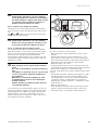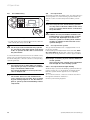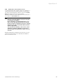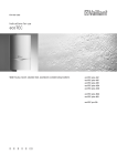
1
For the owner
Operating manual
ecoTEC
Gas wall boilers with condensing appliance technology
GB
VU 466/4
VU 656/4
Contents
Appliance characteristics
Recommended accessories
Contents
Appliance characteristics
Vaillant ecoTEC units are compact wall-mounted gas
condensing boilers.
Appliance characteristics...........................................
2
Recommended accessories ........................................
2
1
1.1
1.2
1.3
1.4
1.5
Notes on the documentation...........................
Storage of documents .............................................
Symbols used .............................................................
Validity of the instruction manual ........................
Identification plate....................................................
CE label ........................................................................
3
3
3
3
3
3
2
2.1
2.2
2.3
Safety ................................................................. 4
Erection and adjustment ......................................... 4
Action in case of emergency ................................. 4
Safety instructions ................................................... 4
auroMATIC 560
3
3.1
3.2
3.3
3.4
3.5
3.5.1
3.5.2
3.6
Instructions on operation ................................ 6
Vaillant warranty ...................................................... 6
Intended use ............................................................... 6
Requirements of the installation site .................. 6
Care .............................................................................. 6
Recycling and disposal ............................................ 6
Appliance..................................................................... 6
Packaging .................................................................... 6
Energy saving tips .................................................... 7
VR 61 Mixing Module
4
4.1
4.2
4.2.1
4.2.2
4.3
4.4
4.4.1
4.4.2
4.4.3
4.5
4.5.1
Operation ...........................................................
Overview of the operating elements ...................
Measures prior to commissioning ........................
Opening the isolating elements.............................
Checking system pressure......................................
Start-up........................................................................
Hot water preparation .............................................
Setting the hot water temperature ......................
Deactivating the storage tank mode ...................
Drawing off the hot water ......................................
Setting for the heating mode ................................
Setting the flow temperature
(no controller connected) .......................................
Setting the flow temperature
(using a controller) ...................................................
Switching heating mode off (summer mode) ....
Adjusting the room thermostat or
weather compensator ..............................................
Status displays (for maintenance and
servicing by the engineer) ......................................
Troubleshooting ........................................................
Faults due to water deficiency ..............................
Faults in ignition ........................................................
Faults in the air/flue gas routing ..........................
Feeding the device/heating system .....................
Decommissioning ......................................................
Frost protection ........................................................
Frost prevention system .........................................
Frost protection through draining........................
Maintenance and customer service .....................
VRC 430f
Recommended accessories
4.5.2
4.5.3
4.5.4
4.6
4.7
4.7.1
4.7.2
4.7.3
4.7.4
4.8
4.9
4.9.1
4.9.2
4.10
2
8
8
10
10
10
11
11
11
12
12
12
Vaillant provides, for control of the ecoTEC, various
controller versions for connection to the terminal rail or
for plugging into the operating plate.
Controller
timeSWITCH 130
timeSWITCH 140
VR 60 Mixing Module
VR 65
VR 68 Solar Module
VR 80 Remote Control
VR 81 Remote Control
VR 90/2 Remote Control
VRC 400
VRC 430
VRC 630/2
vrnetDIALOG 830
vrnetDIALOG 840/2
vrnetDIALOG 860/2
VRT 230
VRT 340f
VRT 360
VRT 360f
VRT 392
12
13
13
VRT 392f
VRT 30
VRT 50
Table 0.1 Controller versions
13
13
14
14
14
15
15
16
16
16
16
17
Your expert technician company will help you select a
suitable controller.
Operating manual ecoTEC 0020052777_00
Notes on the documentation 1
1
Notes on the documentation
The following information is intended to help you
throughout the entire documentation.
Further documents apply in combination with this operating manual.
We accept no liability for any damage caused by nonobserve these instructions.
Other applicable documents
For the owner of the system:
Short operator's manual
For the heating engineer:
Installation and maintenance
instructions
Installation manual for flue pipe
No. 0020040000
No. 0020029172
or
No. 0020029173
1.3
Validity of the instruction manual
This operating manual applies exclusively to units with
the following article numbers:
– 0010004139
– 0010004140
For the article number of your unit please refer to the
identification plate.
1.4
Identification plate
The identification plate of the Vaillant ecoTEC is mounted on the underside of the unit and on the rear of the
electronics box at the factory.
1.5
CE label
CE labelling shows that the appliances comply with the
basic requirements of the applicable directives as stated
on the data badge.
No. 0020046373
The manuals for any accessories and controllers used
also apply.
The Benchmark gas boiler commissioning checklist (in
the operating instruction manual) should be completed
by the expert technician and/or by the technician
present during the commissioning, and handed over to
the operator of the installation.
If you have any questions, after reading through these
instructions, considering the operation of the boiler,
please contact your expert technician or the technical
department of Vaillant.
1.1
Storage of documents
Please store this operating manual and other applicable
documents where they are accessible at all times.
If you move out or sell the appliance, pass on the documents to the buyer.
Note!
h Vaillant
Ltd. supports the Benchmark Initiative.
You will find the benchmark gas boiler commissioning checklist in the appendix to these installation instructions. It is very important
that this document be filled out properly when
installing, commissioning and handing-over to
the operator of the installation.
1.2
Symbols used
Please observe the following when operating the unit:
Safety instructions in this operating instruction manual!
Danger!
d Immediate
risk of serious injury or death!
H Danger!
Danger of burning or scalding!
a Caution!
Potentially dangerous situation for the product
and environment!
h Note!
Useful information and instructions.
• Symbol for a necessary task
Operating manual ecoTEC 0020052777_00
3
2 Safety
2
Safety
2.1
Erection and adjustment
Installation and adjustment of the boiler and service,
maintenance and repair work may only be carried out
by expert technicians in accordance with regulations introduced in 1998 governing the safety of gas installations (installation and use). (In Great Britain "CORGI".
This means that the work carried out by registered installation companies must always be to a safe and satisfactory standard.) If the boiler is mounted in a cabinettype enclosure the ventilation openings must not be obstructed and the enclosure must not be used for storage purposes.
2.2
1
Action in case of emergency
Fig. 2.1 Closing the gas isolator cock
d
Danger!
If you smell gas!
Risk of poisoning and explosion due to a
malfunction!
Procedure in case of gas smell in buildings
• Open doors and windows wide, facilitate through
movement of air, stay out of rooms where gas odour
is present!
• Avoid naked flames, do not smoke, do not use pocket
lighters!
• Do not use electric switches, plugs, bells, telephones
and other communication systems in the building!
• Close gas meter isolator device or main isolator device!
• Close gas isolator cock (1, Fig. 2.1) on unit!
• Warn other building residents, but avoid ringing doorbells!
• Vacate building!
• Inform the gas supply company stand-by service from
a telephone outside the building!
• If a gas leak is audible, leave the building immediately,
prevent others from entering the building and notify
the police and fire brigade from outside the building!
2.3
Safety instructions
Always observe the following safety instructions and
regulations.
Danger!
d Inflammable
mixtures of gas and air may ex-
plode!
Do not use or store explosives or highly flammable substances, such as petrol or paint, in
the same room as the unit.
Danger!
d Risk
of poisoning and explosion due to a mal-
function!
Never put the safety devices out of operation
or tamper with them so as to impair their
function.
Therefore, do not attempt any modifications:
- to the unit,
- around the unit,
- to the gas, air, water and electricity supply pipes,
- to the expansion relief valve and drain line for the
heating water,
- to the flue gas pipes.
This also applies to alterations to structural elements in
the vicinity of the appliance which might affect its operational safety.
Example:
- If you require cabinet-type cladding for your unit, consult your recognised expert technician company.
Under no circumstances must you enclose your device
arbitrarily. Enclosing the appliance in a cabinet requires observance of special design instructions.
For alterations to the appliance or to its environment,
you must refer to the suitably qualified heating engineer which is responsible for it.
4
Operating manual ecoTEC 0020052777_00
Safety 2
Caution!
a Inappropriate alterations can cause damage!
If you wish to keep the unit ready for operation using an
emergency generating set in the event of a power failure, the technical specification of the unit (frequency,
voltage, earthing) must match the power mains, and
must correspond at least to the power consumption of
your unit. Contact your expert technician company for
advice.
• Do not damage or remove seals on components. Only
a suitably qualified heating engineer or our customer
service may remove sealed components.
Frost protection
If you are going to be away during a cold period, make
sure the heating system remains in operation and that
the rooms are sufficiently heated.
Under no circumstances should you attempt to
make alterations to the gas wall-mounted boiler
or other parts of the system.
Never try to carry out maintenance work or repairs on the appliance yourself.
Danger!
H Risk of scalding!
The water coming out of the tap can be very
hot.
Caution!
a Risk of damage!
Do not use sprays, solvents, chlorinated cleaning agents, paint, adhesives or similar substances in the vicinity of the appliance. These
substances can cause corrosion, even in the
flue system.
Caution!
a Risk
of damage!
If there is a power cut or if the room temperature is set too low in individual rooms it can
not be ruled out that sections of the heating
system are damaged by frost.
Always observe the information on frost protection provided in Chapter 4.9.
Installation and setting
a Caution!
Installation of the unit may only be undertaken
by a recognised specialised technician in accordance with "Gas Safety (Installation and
Use) Regulations 1998".
In IE the installation must comply with the current Version of I.S.813 ‘Domestic Gas Installations’ (gas installations in private households)
and the current Building Regulations. The current ETCI Regulations for the installation of
electrical equipment must also be observed.
Caution!
a The unit may only be operated continuously
with its cladding properly closed! Otherwise,
under unfavourable conditions, it can result in
material damage or even injury or death.
Filling pressure of the heating system
Regularly check the filling pressure of the heating installation, see Chapter 4.7.4.
Emergency power supply
Your heating engineer connected your gas wall-mounted heating device to the mains supply during installation.
Operating manual ecoTEC 0020052777_00
5
3 Instructions on operation
3
Instructions on operation
3.1
Vaillant warranty
Vaillant provide a full parts and labour warranty for this
appliance.
The appliance must be installed by a suitably competent
person in accordance with the Gas Safety (Installation
and Use) Regulations 1998, and the manufacturer’s instructions. In the UK ‘CORGI’ registered installers undertake the work in compliance with safe and satisfactory
standards. All unvented domestic hot water cylinders
must be installed by a competent person to the prevailing building regulations at the time of installation. (G3)
Terms and conditions apply to the warranty, details of
which can be found on the warranty registration card
included with this appliance.
Failure to install and commission this appliance in compliance with the manufacturer’s instructions may invalidate the warranty (this does not affect the customer’s
statutory rights).
3.2
Intended use
The Valliant atmo ecoTEC wall boilers are state-of-theart appliances which have been constructed in accordance with recognised safety regulations. Nevertheless,
there is still a risk of injury or death to the user or others or of damage to the device and other property in
the event of improper use or use for which it is not intended.
This unit is not intended for use by persons (including
children) having limited physical, sensory or mental capacities or who have inadequate experience and/or
knowledge, unless supervised by a person responsible
for their safety or who has been given instructions from
them as to how to operate the unit. Children must be
watched to ensure that they do not play with the unit.
The units are intended as heat generators for closed
hot-water central heating installations and for central
hot water preparation. Any other or additional use is
considered to be improper. The manufacturer or supplier is not liable for any resulting damage. The user alone
bears the risk.
Intended use includes the observance of the operating
and installation manual and all other applicable documents, as well as adherence to the maintenance and inspection conditions.
3.3
Requirements of the installation site
The Valliant ecoTEC gas wall boilers are installed on the
wall so that condensation can be diverted and so that
the flue system pipes can be laid.
They can be installed in basements, storage rooms, utility rooms or living areas. Ask your heating engineer
which national regulations must be observed.
Note!
h It is not necessary to keep a clearance between
the appliance and combustible materials or
components, since at the rated heating power
of the appliance the temperature at the surface
of the housing is always lower than the maximum allowed temperature of 85 °C.
3.4
Care
• Clean the cladding of your unit with a damp cloth and
a little soap.
Caution!
a Risk
of damage
Do not use scouring or cleaning agents which
might damage the cladding, fittings or controls.
Do not use sprays, solvents or cleaning agents
containing chlorine.
3.5
Recycling and disposal
Both your Valliant ecoTEC gas wall boiler and its packaging consist mainly of recyclable raw materials.
3.5.1 Appliance
Do not dispose of your Valliant ecoTEC gas-fired wallmounted unit or any of its accessories in the household
waste. Make sure the old appliance and any accessories
are disposed of properly.
3.5.2 Packaging
Leave the disposal of the transport packaging to the
qualified servicing company which installed the appliance.
Note!
h Please
observe the applicable national legal
regulations.
a Caution!
Any improper use is forbidden.
6
Operating manual ecoTEC 0020052777_00
Instructions on operation 3
3.6
Energy saving tips
Installing a weather compensator
Weather-compensators regulate the heating feed temperature with reference to the outside temperature. No
more heat is generated than is currently required. The
designated heating flow temperature for the corresponding outside temperature must be set on the
weather compensator. This setting must not be greater
than required by the heating installation design. The
correct setting is normally undertaken by the heating
engineer. The required heating and set-back phases
(e.g. at night) are automatically switched on/off using
integrated timer programs. Weather compensators combined with thermostat valves are the most economical
form of heating regulation.
Reducing the heating system
Reducing the room temperature at night and in your absence. This is most easily and reliably achieved using
controllers with timer programs that can be selected according to individual requirements. At such times, set
the room temperature approx. 5 °C lower than during
full heating times. Reduction of more than 5 °C brings
no additional energy saving, because then increased
heating capacities would be needed for the next full
heating period. Only for longer absences, e.g. holidays,
is it worthwhile to further lower the temperatures. However, in winter, make sure that there is adequate frost
protection.
Room temperature
Set the room temperature only as high as would be
enough for your comfort level. An extra degree would
mean increased energy consumption of about 6%. Adjust the room temperature according to the use of the
specific room. For example, normally, bedrooms or seldom used rooms are heated to 20 °C.
Setting the operating mode
In warmer seasons, when the apartment needs no heating, turn the heating to summer mode. The heating
mode is then shut off, however, the device or the plant
remains ready for operation for water heating.
Uniform heating
Often, in an apartment with central heating, only one
room is heated. Adjacent rooms are also heated without
regulation by the enclosing surfaces of the room, i.e.
walls, doors, windows, roofs, floors, which means that
an unwanted loss of thermal energy occurs. In these
kind of operating conditions the power of the radiator in
this heated room is obviously insufficient. Consequently,
the room cannot be heated adequately and an uncomfortable feeling of coolness prevails (the same effect is
produced when doors between heated and unheated or
partially heated rooms remain open). This is incorrect
saving: The heating is in operation and still the room
temperature is not comfortably warm.
Operating manual ecoTEC 0020052777_00
Greater heating comfort and a more practical operating
mode is achieved when all rooms in an apartment are
heated uniformly and in accordance to their usage. The
building structure can also suffer if components of the
building are unheated or only inadequately heated.
Thermostat valves and room thermostat
Nowadays, all radiators should be fitted with thermostatic valves as a matter of course. They maintain the
set room temperature precisely. You can adjust the
room temperature to suit your individual requirements
and ensure effective operation of your heating installation using thermostatic valves in combination with a
room thermostat (or weather compensator). All the radiator valves should be fully opened in the room where
the room thermostat is located, as otherwise the two
control systems will influence one another and the regulation quality will be adversely affected. Incidentally, the
following user behaviour is frequently observed: As
soon as the room becomes too hot the user turns the
thermostatic valve off (or specifies a lower temperature
at the room thermostat). If after a period of time the
user feels cold and opens the thermostatic valve again.
This procedure is not only inconvenient, it is also completely unnecessary as a correctly functioning thermostatic valve does this automatically: If the room temperature rises above the value set on the sensor head, the
thermostat valve shuts off automatically, when the temperature drops below the defined value, it opens again.
Do not cover regulators
Do not cover your regulators with furniture, drapes or
similar objects. The room air must circulate unhindered.
Covered thermostat valves can be equipped with remote sensors and thus still work.
Appropriate hot water temperature
The hot water should only be heated to the required
temperature. Any further heating results in unnecessary
power consumption and hot water temperatures of
more than 60 °C also lead to increased lime scale reduction.
Energy-conscious use of water
Energy-conscious use of water can also reduce costs
considerably. e. g. showering instead of bathing: whereas about 150 litres of water are required for a bath, a
modern shower equipped with water saving fittings uses
around a third of this quantity. By the way: a dripping
water tap wastes up to 2000 litres of water and a leaking toilet flush up to 4000 litres of water each year. A
new seal costs very little by comparison.
Run circulation pumps only if needed
Circulation pumps facilitate the continuous circulation
of hot water through the piping system which means
that hot water is immediately available, also at more
distant draw-off points.
7
3 Instructions on operation
4 Operation
These pumps undoubtedly enhance the convenience of
the hot water generation process. But they also need
power. And circulating hot water that is not used cools
off when passing through pipes and then needs to be
reheated. Therefore, circulation pumps are to be operated only when hot water is actually needed for the
household. Individual timer programs can be defined
using switching clocks, which are already installed or
can be retrofitted in most circulation pumps. Weather
compensators often have ancillary functions for controlling circulation pump timings. Consult your heating engineer. Another option is to turn on the circulation only
for concrete needs for a specific period of time by using
a button or switch installed near a frequently used
water plug. A corresponding button can be connected to
the Vaillant ecoTEC electronics.
Ventilating residential spaces
During the heating period, open windows only for ventilation and not for temperature regulation. A brief impact-ventilation is more effective and energy-saving
than windows that are kept open for a long time. We
recommend that the windows be opened fully for a
short period. When ventilating the room, close all thermostatic valves in the room or specify the minimum
temperature at the room thermostat (if installed). These
measures guarantee a sufficient exchange of air and
avoid unnecessary cooling and loss of energy (e.g. due
to unwanted activation of the heating system during
ventilation).
8
4
4.1
Operation
Overview of the operating elements
1
10
2
9
3
8
7
4
6
5
Fig. 4.1 Operating elements ecoTEC
To open the front panel, hold the recess and pull it
down. You can now see the controls with the following
functions (cp. Fig. 4.1):
1
Display indicating the current heating flow temperature, the filling pressure of the heating system, the operating mode and other additional
information
2
Button "i" for calling up information
3
Controller (accessory)
4
Pressure gauge showing the filling or operating
pressure in the heating system
5
Button for switching the unit on and off.
6
"+" button for navigating forwards through the
display view (used by expert technician to specify settings and for troubleshooting) or displaying
the storage temperature (VU with cylinder
sensor)
7
"–" button for navigating backwards through the
display view (used by expert technician to specify settings and for troubleshooting) and for displaying the filling pressure of the heating system
8
"Fault resolution" button for resetting the system in the case of specific faults
9
Rotary knob for setting the heating feed
temperature
Operating manual ecoTEC 0020052777_00
Operation 4
10
Rotary knob for specifying the storage temperature (in conjunction with VU units with connected domestic hot water cylinder VIH)
This operating mode cannot be ended:
- by pushing the button (8) "Fault reset"
or
- by switching the unit on or off.
Digital Information and Analysis System (DIA)
1
Hot water preparation active
permanently on: Operating mode heating
flashes:
Burner lockout time active
Hot water preparation active
permanently on:
recharging operating
mode on standby
Flashing:
Hot water storage tank
is being heated, burner
on
Internal pump is in operation
Fig. 4.2 Display ecoTEC
A Digital Information and Analysis System is fitted in
ecoTEC units. This system provides information on the
operating status of your appliance and helps you deal
with problems.
During normal operation, the display (1) shows the current heating feed temperature (in this example 45 °C).
In the event of a fault, an error code appears instead of
the temperature.
You can also see the following information from the
symbols displayed:
1
Actuating internal gas valve
Flame with cross:
Fault during burner operation;
Unit is switched off
Flame without cross:
Burner operation normal
The current heating flow temperature, the heating system filling pressure or a status or error
code
Flue problem
Flue problem
Only in combination with the vrnetDIALOG:
As long as this symbol appears in the display, the
heating feed temperature and hot water outlet
temperature are specified by vrnetDIALOG (accessory), which means the unit operates at temperatures other than those set using the rotary
knobs (9) and (10).
This operating mode can only be ended:
- via vrnetDIALOG or
- by altering the temperature setting at the rotary knobs (9) or (10) by more than ± 5 K.
Operating manual ecoTEC 0020052777_00
9
4 Operation
4.2
Measures prior to commissioning
4.2.1
Opening the isolating elements
• Check the filling pressure of the system using the
pressure gauge (1) before putting it into operation.
For the heating installation to operate correctly the indicator for the pressure gauge (1) must be in the upper
half of the dark grey area when the system is cold (see
Fig. 4.4). This corresponds to a filling pressure between
1.0 and 2.0 bar. If the indicator is in the area with the
light grey background, the system must be topped up
with water before starting up (see Chapter 4.7.4).
h Note!
The isolator devices are not included in the
scope of delivery for your unit. They are fitted
by your heating engineer on site. He must explain to you the position and handling of these
components.
Note!
h The ecoTEC unit is equipped with a pressure
gauge and a digital pressure indicator.
The pressure gauge allows you to quickly check
that the filling pressure is within the target
range when the appliance is turned off. When
the unit is in operation, you can have the exact
pressure shown in the display. Activate the
pressure display by pressing the "-" button (2).
After 5 seconds the display returns to the feed
temperature. You can also switch continuously
between the temperature and pressure in the
display by keeping the "-" button pressed for
roughly 5 seconds.
3
2
Note!
h Note:To
avoid running the system with too lit-
1
Fig. 4.3 Open isolator devices (maintenance cocks, for
example)
• Open the gas isolator cock (2) by pressing it in and
turning it anticlockwise until it reaches the limit stop.
• Check that the supply (3) and return (1) maintenance
cocks are open. This is the case when the handles of
the maintenance cocks are parallel to the direction of
the piping.
tle water and thus prevent damage, your appliance has a pressure sensor. This signals the
low pressure level if the level falls below 0.6
bar by the water pressure value in the display
flashing.
If the pressure falls below 0.3 bar the unit
switches off. The error message F.22 appears
in the display. Fill the system up with water before you start up the appliance again.
If the heating system extends over several floors, the
system may require a higher filling pressure. Ask your
engineer for details.
4.2.2 Checking system pressure
2
1
Fig. 4.4 Check the filling pressure of the heating system
10
Operating manual ecoTEC 0020052777_00
Operation 4
4.3
Start-up
4.4.1
Setting the hot water temperature
2
2
3
1
Fig. 4.6 Setting the water temperature
Fig. 4.5 Switching the appliance on
• Use the main switch (1) to switch the appliance on and
off:
1:
"ON"
0:
"OFF"
When you switch the unit on the display (2) shows the
current heating feed temperature.
To customise the settings in the unit, read Chapters 4.4
and 4.5 where the options for the hot water generation
and heating mode settings are described.
a Caution!
Risk of damage!
The frost protection and monitoring systems
are only active if the main switch of the unit is
in the "I" position and the unit is connected to
the power mains.
To ensure that these protection devices remain active,
switch your gas wall-mounted boiler on and off using
the controller (see the corresponding operating
manual).
Chapter 4.8 describes how you can fully shutdown your
gas-fired wall-mounted boiler.
4.4
Hot water preparation
To generate hot water in conjunction with the VU unit
type a VIH-type domestic hot water cylinder must be
connected to the boiler.
Operating manual ecoTEC 0020052777_00
• Switch on the unit as described in Chapter 4.3.
• Specify the storage temperature you require using
the corresponding rotary knob (3). In doing this:
- left-hand limit stop,
frost protection
- right-hand limit stop,
approx. 15 °C
max. 70 °C
When you set the desired temperature, the respective
nominal value is shown on the display (2).
This display disappears after 3 seconds and is replaced
by the standard display (current heating feed temperature or water pressure in the system (optional).
Danger!
d Health
danger from formation of Legionella!
If the unit is used for post-heating within a
solar-supported drinking water heating installation, set the hot water outlet temperature to at
least 60 °C via the rotary knob (3).
Caution!
a Risk of calcification!
If the water hardness is more than
3.57 mol/m3 (20 °dH), do not turn the rotary
knob (3) beyond the middle position.
h IfNote!
your controller is connected to a dual-cable
eBUS line, specify the highest possible hot
water temperature using the corresponding rotary knob. Specify the set target temperature
for your cylinder at the controller.
11
4 Operation
4.4.2 Deactivating the storage tank mode
In VU units connected to domestic hot water cylinders
you can deactivate the hot water generation or recharging operation whilst keeping the heating system in
operation.
• Turn the rotary knob for setting the hot water temperature all the way to the left. Only the frost protection function for the cylinder remains active.
4.5
Setting for the heating mode
4.5.1
Setting the flow temperature (no controller
connected)
2
4.4.3 Drawing off the hot water
1
1
Fig. 4.8 Setting the flow temperature without a controller
4.7 Drawing off hot water
Hot water is drawn from the connected cylinder when a
hot water tap (1) is opened at a draw-off point (washbasin, shower, bathtub, etc.)
If the storage temperature falls below the set temperature, the VU unit starts up automatically and reheats
the cylinder. The VU unit switches off automatically
when the cylinder reaches the set target temperature.
The pump continues to run for a short while.
If there is no external controller, set the flow temperature using the knob (1) according to the outside temperature. We recommend the following settings:
– Left position (but not all the way) in spring and autumn: Outside temperature approx. 10 to 20 °C
– Mid-position setting in reasonably cold weather:
Outside temperature approx. 0 to 10 °C
– Right position in very cold weather:
Outside temperature approx. 0 to –15 °C
When you adjust the temperature, the value specified is
shown in the display (2). This display disappears after
3 seconds and is replaced by the standard display
(current heating feed temperature or water pressure in
the system (optional)).
The settings at the rotary knob (1) are normally infinitely variable up to a feed temperature of 75 °C. However,
if higher temperatures can be set on your appliance,
have your engineer make adjustments so that you can
operate the heating system at higher flow
temperatures.
12
Operating manual ecoTEC 0020052777_00
Operation 4
4.5.2 Setting the flow temperature (using a controller)
4.5.4 Adjusting the room thermostat or weather
compensator
1
1
Fig. 4.9 Setting the flow temperature using a controller
If your boiler has a room thermostat or weather compensator, you must make the following settings:
• Turn the rotary knob (1) for the heating feed temperature all the way to the right.
The flow temperature is automatically adjusted by the
controller (for information, see its operating manual).
4.5.3
2
Fig. 4.11 Setting a room thermostat or weather compensator
• Set the room thermostats (1), weather compensators
or radiator thermostat valves (2) as specified in the
operating manuals for these accessories.
Switching heating mode off (summer mode)
4.6
Status displays (for maintenance and servicing by the engineer)
1
1
Fig. 4.10 Switching off heating (summer operation)
2
You can switch off the heating in summer without
switching off the hot water supply.
• Turn the rotary knob (1) for setting the heating feed
temperature all the way to the left.
Operating manual ecoTEC 0020052777_00
Fig. 4.12 Status displays
The status displays provide information on the operating status of the unit.
• Press the "i" button (2) to activate the status
displays.
The display (1) then shows the individual status codes, e.
g. "S. 4" for burner operation. The table below explains
the most important status codes.
In switching phases, for example on starting up again
after the flame was extinguished, the status message
"S." briefly appears.
• Press the "i" button (2) again to switch the display
back to normal mode.
13
4 Operation
Display
Meaning
Displays during heating operation
S. 0
Heating, no heat demand
S. 1
Heating mode, fan start-up
S. 2
Heating mode, pump flow
S. 3
Heating mode, ignition
S. 4
Heating mode, burner on
S. 6
Heating mode, fan overrun
S. 7
Heating mode, pump overrun
S. 8
Heating, remaining cut-off time xx min
S.31
no heat demand, summer operating mode
S.34
Heating mode, frost protection
Displays in storage tank charging
S. 20
Hot water requirement
S.22
Hot water handling, pump flow
S.24
Hot water operation burner on
Service message (appears as necessary and replaces
the normal status text)
S.85
Caution!
a Inappropriate alterations can cause damage!
If your gas-fired wall-mounted boiler is still not
working properly after you have checked the
above points, consult a recognised expert technician company or Vaillant Service Solutions
for advice.
4.7.1 Faults due to water deficiency
The device switches to "Fault" if the filling pressure in
the heating system is too low. This malfunction is indicated by the fault codes "F.22" (dry fire) or "F.23" or
"F.24" (water shortage). You can only start up the appliance again when the heating system is sufficiently
filled with water.
If the pressure drops frequently the reason for the loss
of hot water must be identified and eliminated by a recognised expert technician company.
4.7.2
Faults in ignition
1
Service message, quantity of circulation water
Table 4.1 Status codes and what they mean (selection)
4.7
Troubleshooting
If you have problems operating your gas-fired wallmounted boiler, you can check the following points
yourself:
No hot water, heating stays cold; Appliance does not
start:
– Are the gas isolator cocks for the building supply and
the appliance open (see Chapter 4.2.1)?
– Is the power supply switched on?
– Is the main switch on the gas-fired wall-mounted boiler switched on (see Chapter 4.3)?
– Is the rotary knob for setting the feed temperature on
the gas-fired wall-mounted boiler not turned to the far
left, i.e. frost protection active (see Chapter 4.4)?
– Is the filling pressure of the heating installation sufficient (see Chapter 4.2.2)?
– Is there air in the heating installation?
– Is there a fault in the ignition process (see Chapter 4.7.2)?
2
Fig. 4.13 Troubleshooting
If the burner fails to ignite after five attempts, the unit
will not operate and switches to "Fault". This is indicated by the error code "F.28" or "F.29" on the display.
In addition, the display shows a flame symbol with a
cross through it (1).
Automatic ignition can only take place after you manually reset the fault.
• In this case, press the fault suppression button (2)
and hold it down for roughly one second to reset the
fault.
Hot water operation, no problem; Heating does not
start:
– Has the external controller (e.g. calorMATIC
controller) signalled a heat requirement (see Chapter 4.5.4)?
14
Operating manual ecoTEC 0020052777_00
Operation 4
Caution!
a Inappropriate alterations can cause damage!
3
If your gas-fired boiler still does not start after
the third attempt to suppress the fault, consult
a recognised expert technician company or
Vaillant Service Solutions for advice.
4.7.3 Faults in the air/flue gas routing
The appliances are fitted with a blower. If the blower
does not work properly, the appliance will switch itself
off.
and
symbols as well as the error message
The
"F.32" appear in the display.
2
1
a
Caution!
Inappropriate alterations can cause damage!
If this error message appears consult a recognised expert technician company for advice.
4.7.4 Feeding the device/heating system
The filling pressure must be between 1.0 and 2.0 bar
when the system is cold in order for the heating installation to operate properly (see Chapter 4.2.2). If the
pressure is less, top up the system with water.
If the heating system extends over several floors, the
system may require a higher filling pressure. Ask your
engineer for details.
Caution!
a Risk of damage to the gas-fired wall-mounted
boiler!
Use only clean tap-water to fill the heating system.
The addition of chemicals such as e.g. frost and
corrosion prevention materials (inhibitors) is
not permitted.
Otherwise it could result in damage to seals
and diaphragms as well as noises during the
heating operation.
Vaillant assumes no liability for this and such
consequential damages.
To fill up and to re-fill the heating system, you can normally use tap water. However in exceptions, the water
quality might not be suitable for filling in the heating
system (heavily corrosive or extremely calciferous
water). In these kind of situations contact your recognised expert technician company.
Operating manual ecoTEC 0020052777_00
Fig. 4.14 Filling the heating installation
Proceed as follows to fill the system:
• Open all radiator valves (thermostat valves) of the
system.
• Connect the filling tap of the installation to a cold
water draw-off valve with a hose (your heating engineer should have shown you the filling fittings and explained the filling and draining of the system).
• Open the filling cock slowly.
• Slowly turn the draw-off valve on and top up the system with water until the required pressure is shown at
the pressure gauge (1) or in the display (3).
You can call up the precise value for the pressure in the
display.
• Activate the pressure display by pressing the "-" button (2). After 5 seconds the display returns to the
feed temperature. You can also switch between the
continuous display of temperature or pressure by
keeping the "-" button pressed for roughly 5 seconds.
• Turn the tap off.
• Bleed all the radiators.
• Then check the installation pressure at the pressure
gauge or display and add more water if necessary.
• Close the filling cock and remove the filling hose.
15
4 Operation
4.8
Decommissioning
4.9
Frost protection
The heating system and water pipes are sufficiently protected against frost if the heating system remains on
and the rooms are sufficiently heated while you are
away.
Caution!
a The
frost protection and monitoring systems
are only active if the main switch of the unit is
in the "I" position and the unit is connected to
the power mains.
Caution!
1
Fig. 4.15 Switching off the appliance
• To shut down your gas wall-mounted boiler, turn the
main switch (1) to the position "0".
a Caution!
The frost protection and monitoring systems
are only active if the main switch of the unit is
in the "I" position and the unit is connected to
the power mains.
To ensure that these protection devices remain active,
switch your gas wall-mounted boiler on and off in normal mode using the controller (see the corresponding
operating manual).
h Note!
For longer periods of shut-down (e.g. holiday
periods), the gas stop-cock and the cold water
stop-cock should be switched off.
For relevant information on frost protection
refer to Chapter 4.9.
Note!
h The isolator devices are not included in the
scope of delivery for your unit. They are fitted
by your heating engineer on site. He must explain to you the position and handling of these
components.
16
a Addition of frost preventative medium to the
heating water is not permitted. This could affect seals and diaphragms and cause noise
when the system is in heating mode. Vaillant
assumes no liability for this and such consequential damages.
4.9.1 Frost prevention system
The gas wall-mounted boiler is equipped with a frost
protection system:
If the heating feed temperature falls below 5°C when
the main switch is on, the unit comes into operation
and heats the heat generation circuit to approx. 30°C.
Caution!
a Danger
of freezing of parts installed within the
overall system!
The frost protection system can not guarantee
flow through the entire heating system.
4.9.2 Frost protection through draining
Another way to protect the heating system and the appliance from frost is to drain them. You must ensure
that the system and the appliance are completely
drained.
All cold and hot water conductors in the house and in
the appliance must be drained too.
Contact your heating engineer.
Operating manual ecoTEC 0020052777_00
Operation 4
4.10
Maintenance and customer service
To ensure that the unit is always ready for operation, is
operationally safe and reliable and has a long working
life, inspection/maintenance must be carried out annually by an expert technician or by Vaillant.
Further information can be obtained from Vaillant Service Solutions . (0870 6060 777).
Danger!
d Danger of property damage and personal injury
from improper handling!
Never attempt to perform maintenance or repairs on the gas wall-mounted boiler yourself.
Assign an approved qualified servicing company
with this work. We recommend making a maintenance agreement.
The operational reliability of the device can be
impaired, resulting in damage to property or
personal injury, if maintenance work is not carried out.
Regular maintenance maximises the efficiency of your
gas-fired wall-mounted boiler and therefore makes it
more economical to run.
Operating manual ecoTEC 0020052777_00
17
0020052777_00 GB 10 2007