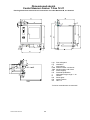
1
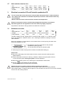
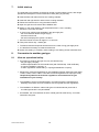
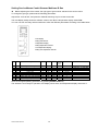
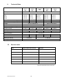
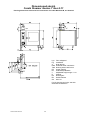
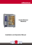
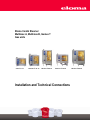
Eloma Combi Steamer
Multimax A, Multimax B, Genius T
Gas units
nius T 6-11
Genius T 10-11
Genius T 20-11
Genius T 12-21
Installation and Technical Connections
791342 Inst. Gas 2.0
1
Genius T 20-21
Installation instructions
Installation instructions
Combi Steamer Multimax B / Genius T Gas
6-11, 10-11, 20-11, 12-21, 20-21
Table of contents
Set up ............................................................................................................................................3
Equipment set up .......................................................................................................................3
Table top models 6-11 and 10-11..............................................................................................3
Floor models 20-11, 12-21 and 20-21 ......................................................................................3
Hints for setting up .....................................................................................................................4
Removal of protecting film .........................................................................................................4
Noise level..................................................................................................................................4
Exhaust air .................................................................................................................................4
2.
Water supply EWk / TWk...............................................................................................................5
2.1
Softened water connection ........................................................................................................5
2.2
Hard water connection ...............................................................................................................5
2.3
Autoclean Optional Equipment ..................................................................................................5
2.4
Diagram of connection ...............................................................................................................6
2.4.1
Water connection for fresh water with water softener ........................................................6
2.4.2
Water connection for Osmosis / Softened water and fresh water ......................................6
2.4.3
Water connection for Osmosis / Softened water ................................................................6
2.5
Water pressure ..........................................................................................................................6
2.6
Max. flow rate.............................................................................................................................6
2.7
Heat emission into the area .......................................................................................................7
3.
Electrical connection EZ und Potential equalisation PE................................................................7
3.1
Standard connection ..................................................................................................................7
4.
Water drain A.................................................................................................................................8
5.
Installation instructions ..................................................................................................................9
5.1
Setting–up possibilities ..............................................................................................................9
5.1.1
Set up under extractor hood ...............................................................................................9
5.1.2. Set-up unobstructed in the room (natural ventilation) ........................................................9
5.1.3. Connection to exhaust gas systems (natural lift or forced ventilation) ............................ 10
6 Connect mains cable...................................................................................................................... 11
7.
Initial start-up .............................................................................................................................. 12
8.
Conversion to another gas type ................................................................................................. 12
8.1
Hints on operational safety ..................................................................................................... 12
8.2
Reference values – Settings ................................................................................................... 13
9.
Technical Data............................................................................................................................ 16
10.
Service notes .............................................................................................................................. 16
Dimensioned sketches…………………………………………………………………………………..17
1.
1.1
1.2
1.3
1.4
1.5
1.6
1.7
Article No. 791342
Version 2.0 2/2007
Explanation of symbols:
Î Activities to be carried out
•
Notes, functional sequences
791342 Inst. Gas 2.0
1
Dear customer,
These installation instructions contain details about setting, installing and adjusting
the combi steamers Genius T 6-11, 10-11, 20-11, 12-21 and 20-21 Gas. Pass on
these instructions to the gas fitters and ensure that they are precisely followed when
the combi steamer is being installed, otherwise functional faults may occur.
After use, keep the installation instructions in a safe place. !
Enter data from the type plate here !
This type plate is fitted
- on the left side of the appliance
- in the electrical area ( for the service technician)
Whenever you need servicing for your combi steamer, please inform these data to
the technician /the after sales-service. This helps your questions to be dealt with
more rapidly.
Eloma GmbH D-82216 Maisach
Geräte Typ:
Geräte Nr.:
Geräteart: A3,B13,B23
Baujahr:
DE
AT, CH
ES, PT, IE, GB
NO, SE, DK, FI
FR
NL
LU
GR, IT
BE
PN
p (mbar)
20/20 ; 50/50
20 ; 50/50
20 ; 37
20 ; 30/30
20/25 ; 37
25 ; 30/30 ; 50/50
20 ; 50/50
20 ; 30/37
20/25 ; 37
QN
Zul. Vorlauftemperatur: 50
Zul. Wasserdruck:
Cat.
II2ELL3B/P
II2H3B/P
II2H3P
II2H3B/P
II2Esi3P
II2L3B/P
II2E; I3B/P
II2H3B/P
I2E(s)B; I3P
(Hi)
°C
200-600 kPa
kW
PIN: CE0063BO3823
Made in Germany
0063
IPX5
Observe vigorously the local regulations, prescriptions and
standards of your country for the installation of catering gas
appliances. Refer to the EC Gas Appliance Directive 90/396/EEC
791342 Inst. Gas 2.0
2
1.
Set up
1.1
Equipment set up
Follow the local regulations and observe the instructions for the installation of
kitchen and shop equipment.
− In case of installation close to materials that risk burning, observe the instructions of fire
prevention.
− Avoid to have any other heat and/or steam sources behind or next to the unit. If this is
impossible, ensure sufficient clearance or provide for appropriate protection. No heat or
humidity must penetrate through the cooling slots into the unit.
− We recommend to install the ovens on top of original Eloma lower racks/supports or else
Eloma warming cabinets WU 14. In case of installations on top of worktables, ensure
sufficient stability and load capacity.
− The equipment must be secured against tilting and falling down.
− No heat or steam sources may be installed underneath the oven.
Transport:
Use elevating truck or fork–lift truck for transport, transport only on pallets.
1.2
Table top models 6-11 and 10-11
−
It is mandatory to set up the appliance in level position. True up minor unevenness with
the vertically adjustable feet.
− Distance to right and left sides at least 50 mm.
− We recommend to leave a distance of 50 mm to the rear of the oven, however it is possible
to set it up right against the wall.
− Weight of the Table models:
6 x 1/1
10 x 1/1
130 kg
170 kg
1.3
Floor models 20-11, 12-21 and 20-21
− Floor models must invariably be operated with the trolley, also when preheating and cleaning.
− Observe the load capacity of the floor. Is the installation location accessible regarding the
appliances measurements.
− Weight of the floor models.
12 x 2/1
20 x 1/1
20 x 2/1
350 kg
300 kg
500 kg
− Floor models need at least 500 mm clearance to the left side, to ensure access for service.
We recommend 800 mm, it is then possible to park the trolley on this side.
791342 Inst. Gas 2.0
3
− For maintenance and easy access to the unit for service operations use flexible water and
electric connections.
The appliance should be removable approximately 1 meter from its standard position.
1.4
Hints for setting up
− The floor underneath the appliance must be plane to ensure a smooth driving-in of the
trolley (roll-in pan-rack).
In case of a sloping floor underneath the unit, the trolley will be placed in an oblique position,
which might influence its proper functioning.
− Minor unevenness can be trued up using spacers at the wheel fastenings.
Major unevenness must be adjusted on site.
− Fix the appliance after adjusting the level and angle, so that the oven can’t shift anymore.
− There should be a minimum distance of 15 +/- 5 mm between the trolley and the top edge
of the oven cavity bottom.
− The trolley must never touch the door gasket and must be level with the appliance
Door gasket
15mm ± 5
1.5
Spacer
Removal of protecting film
− Prior to starting the machine, the protective film must be removed from side, back and
cover surfaces. Use special cleaner to clean to perfection.
− Do not operate the oven with the adhesive film.
1.6
Noise level
− The emission value of the noise level is less than 70 dB (A)..
1.7
Exhaust air
− A built-in cooling function cools down water and steam of condensation, which runs down
the drain. It is therefore not necessary, however recommended, to install the appliance
under a ventilation hood.
− If such a hood is installed, its design and power rates should comply with the German VDI
regulation 2052.
− For Eloma combi-steamer a condensation hood is available as an option.
− Observe the installation manual “condensation hood” for proper installation of the hood
791342 Inst. Gas 2.0
4
2.
Water supply EWk / TWk
Connection to the drinking water supply in accordance with the German standard
DIN 1988, section 4 .
− In accordance with DVGW instructions (German Gas and Water Standard), the appliance
is intrinsically safe and can be connected to the drinking water supply without additional
preventive measures.
− Before connecting the oven to the water supply, wash out / clean the building pipe system!
− All appliances are equipped as standard with 2 water-connections for soft water and hard
water.
− Both connections are under the indication plate and both must be connected.
− We recommend to use a pressure-resistant, flexible hose ½ " with R¾" screwing. It should
be DVGW (German Gas and Water Standard) and drinking water approved. Ensure it is
long enough to remove the appliance by approx. 50 cm from its standard position ensuring
easy access for servicing.
− Install an easily accessible water shut-off-valve for every unit.
2.1
Softened water connection
− Meaked with EWk
− To avoid calcareous deposits, we recommend to install a water softener, if the water
hardness exceeds 6° dH (1,08 mmol/litre).
− Physical methods, such as for instance magnetic fields are unsuitable.
− Please observe installation and operation instructions for the water softener.
− Do not use any connections of galvanised steel or any corrodible material between water
softener and the unit. Danger of Rusting !
− Water temperature max. 50°C/ 120 °F, however if possible use cold water.
2.2
Hard water connection
− Meaked with TWK
− Hard water connection (cold water) for cooling down the condensed water.
(Warm water results in increased water consumption, hot water would stop cooling down.
2.3
Autoclean Optional Equipment
Connection
− Refer to the dimensioned sketch for connections of cleaning and rinse agent.
− The label on the oven indicates where the chemicals have to be connected.
Reiniger
Cleaner
Nettoyant
Klarspüler
Rinse agent
Rince-éclat
− Use the supplied clamps to connect the hoses to the oven.
− Red for the cleaner and blue for the rinse agent
− Handling of cleaner and rinse agent: Observe the directions of the manufacturer and wear
suitable protective clothing, gloves and glasses.
Make sure to place the two canisters lower or at the same level as the combi-steamer.
Maximum vertical range from canister to connection = 1,50 m. Maximum hose length = 10 m.
− Remove the lids of the two canisters (cleaner and rinse agent) and screw the screw cap
with hose to the respective canister. Red for the cleaner and blue for the rinse agent.
− Start the installation program Autoclean. Check if cleaner and rinse agent are sucked into
the cooking chamber. If necessary, please repeat the Autoclean “start up” level.
Autoclean is ready for use.
− To detailed data and function of Autoclean see installation and operation manual of the
combi-steamer.
791342 Inst. Gas 2.0
5
2.4
Diagram of connection
2.4.1
Water connection for fresh water with water softener
2.4.2
Water connection for Osmosis / Softened water and fresh water
2.4.3
Water connection for Osmosis / Softened water
2.5
Water pressure
Min. 200 kPa = 2 bar
Max. 600 kPa = 6 bar
2.6
Max. flow rate
Typ
Softened water l/h
Hard water l/h
791342 Inst. Gas 2.0
6-11
15
55
10-11
20
55
6
12-21
25
55
20-11
40
65
20-21
50
65
2.7
Heat emission into the area
Typ
Connected load
latent
sensible
3.
kW
kJ/h
kJ/h
6-11
12.0
4.320
3.672
10-11
20.0
7.200
6.120
20-11
40.0
14.400
12.240
12-21
35.0
12.600
10.710
20-21
70.0
25.200
21.420
Electrical connection EZ und Potential equalisation PE
Do not connect the unit to the mains if it has just been transported from a cold environment
into a warm room. Otherwise condensate may develop inside the combi steamer which may
cause damages.
Wait for about two hours until the unit has reached room temperature
Electrical connections must be carried out by an approved electrician in accordance
with VDE regulations and regulations of the local electricity supply companies
Pay attention to the data on the type plate for the electrical connections.
3.1
Standard connection
Typ
Connected load
Voltage
Fuse protection
kW
Amp.
6-11
10-11
12.0
20.0
230 V, 31 N AC 50 Hz
1x16
1x16
20-11
12-21
40.0
35.0
400 V, 31 N AC 50 Hz
1x16
3x16
20-21
70.0
3x16
The table models units are supplied with a connecting cable, length 2 m. In case this cable
has to be replaced for whatever reason, use a cable type H07RN-F according to German
VDE standards.
Next to the appliance an all-pole electric circuit breaker with a contact opening of at least 3mm
has to be provided for on site.
The appliance must be incorporated into the potential
equalisation system (ground).
You find the terminal under the indication plate.
In case a plug is mounted, the plug device must be accessible after setting-up.
Please note:
Î Do not fit a mains plug to the mains cable. Securely connect the mains cable to prevent
phase distortion.
Î Connect the phase to the brown cable (L), otherwise failures in the gas system will occur.
In such case the symbol “failure gas system“ would be displayed.
Î New start by pressing sensor key “Restart gas“ Combistemamer Genius Gas.
to acknowledge gas fault messages.
Î Use key
Combisteamer Multimax B Gas starts automatically.
Observe the sense of rotation of the fan when connecting to the mains.
Sense of rotation: In steam-mode the fan runs clockwise, check it from the cooking chamber.
Floor models rotation: In steam-mode the upper fan runs clockwise, the lower fan runs counter-clockwise,
check it from the cooking chamber.
791342 Inst. Gas 2.0
7
4.
Water drain A
Connect drain to the waste water system in accordance with the German standard
DIN 1986, section 1.
− For UK the inlet supply shall be fed via fluid backflow prevention category three
arrangement such as a double check valve.
− In accordance with DVGW instructions (DVGW = German technical scientific association
on gas and water) the appliance is intrinsically safe and can be connected directly to the
sewer without any further measures
− Drain and air-vent pipe material must be steam temperature resistant.
Minimum diameter 50 mm, preferably not longer than 1 m, we recommend high temperature
resistant pipes type HT PA-I 1818 according to the German standard DIN 19560.
It is not permitted to taper the cross-section of the drain.
− Slope of at least 5% is necessary.
− Waste water temperature 80°C
To fill the siphon, give about 3 liters of clear water into the oven prior to any first start.
Fixed connection without trap
Fixed connection with trap
Drain fannel
The Eloma GmbH bears no liability for any damages caused by a not proper installation.
791342 Inst. Gas 2.0
8
5.
Installation instructions
5.1
Setting–up possibilities
The DVGW (DVGW = German technical scientific association on gas and water)
and the Technical regulations for liquid gas installations TRGI 86/96 give systematic
information about the different types of gas appliances, their exhaust gas evacuation
and their combustion air supply. Consequently, do observe vigorously the local
regulations, prescriptions and standards of your country for the installation of
catering gas appliances. Prior to setting up discuss the construction of the exhaust
gas system with the local chimney-sweep in charge and record the approved construction.
• Appliances of Type A are defined as units that can be operated without exhaust gas
evacuation installations. (A 3 with blower before the burner)
• Appliances of Type B are defined as units that must be operated with exhaust gas
evacuation installations. (B13, B23 with blower before the burner)
5.1.1
Set up under extractor hood
Exhaust air evacuation system in accordance with DVGW (DVGW = German technical
scientific association on gas and water) work sheet G 634.
Install in accordance with local prescriptions.
Gas appliances in accordance with type B23
which are set up under an extractor hood, do not
need a flow safeguard. The pipe must end under
the flame protection filter with a clearance of 1,25
to 2 times its pipe diameter.
Flame protection filter
• The filters of the extractor hood must be
capable to withstand a waste gas temperature
of 500°C/932° F. Use a flame protection filter.
• If the exhaust gas of gas appliances type B23
is extracted by a hood, precautions have to be
taken to ensure that the gas supply to the
burner is not released unless an extraction is
guaranteed.
5.1.2. Set-up unobstructed in the room (natural ventilation)
• If waste gas out of appliances type B 13 is
exhausted via ventilation ceilings, they must be
equipped with updraft lines and flow guards.
Flow safeguard
• The ceiling/cover materials must be heat
resistant and fireproof.
• The gas fitter
- assesses whether the combustion air supply
and the exhaust gas evacuationare sufficient,
- arranges suitable measures, if these
insufficient (e. g. increase of the ventilation
slots, forced ventilation, connection to waste
gas system).
791342 Inst. Gas 2.0
9
5.1.3. Connection to exhaust gas systems (natural lift or forced ventilation)
Connections to chimneys (with flow safeguard) must be in accordance with the
German Standard DIN 18160, section 1. Connections to an exhaust gas evacuation
system must be according to DVGW regulations, work sheet G 660.
Respectively observe vigorously the local regulations, prescriptions and standards
• The gas fitter will make the necessary
assessment of the room size and ventilation.
Flow safeguard
• Prior to connection to an exhaust gas
evacuation system, send for the area master
chimney-sweep.
• When connecting to an exhaust gas
evacuation, it is necessary to have the flow
safeguard installed.
• Pay attention to the exhaust gas temperatures!
All parts (pipes, fans) which come into contact
with hot exhaust gas must be heat–resistant.
791342 Inst. Gas 2.0
10
6
Connect mains cable
• Connection, conversion and repair of gas–consuming equipment in catering kitchens and
the remedying of faults in equipment of this type, may only be carried out by
- the gas supply company,
- a skilled representative of the manufacturer (with DVGW or any local certificate),
- a contract installation company or
- a sales organisation authorised by a liquid gas distribution company.
• Before making any connections, inform the responsible gas supply company.
Observe the Technical regulations for gas installations DVGW TRGI! (DVGW = German
technical scientific association on gas and water) and refer to work sheets G 600,
G 628, G 634, G 660, G 670 and the Technical regulations for liquid gas TRGI.
Respectively observe the technical regulations and instruction for gas installations
of your country.
• The installation must be carried out in accordance with the manufacturer’s assembly
instructions and in accordance with recognised technical rules.
• The installation of different makes and different types of individual burner parts and of so–
called gas saver units is not permitted.
• Before the combi steamer, a gas shut–off valve must be provided for on site.
• Before connecting, ensure that the set gas type of the appliance is the same as the gas
type available at the site of installation.
•
When setting up the combi steamer for the first time, refer to the information plate
• Ensure that mains connection is protected from mechanical damages and heat.
• Units with a fixed (rigid) connection must be secured to prevent being moved around.
Î Check the gas line pressure.
Measuring stub - gas line pressure
Gas regulating valve
Î After setting up, converting and repairing gas consuming appliances, check all parts
carrying gas for leaks.
791342 Inst. Gas 2.0
11
7.
Initial start-up
The initial start up procedure must also be carried out when setting up unit, after longer
operational interruptions or after maintenance work (filling of gas inlet).
Î Insert fat filter and drain sieve into the cooking chamber
Î Insert left and right hand-in racks into the cooking chamber.
Î Follow the instructions for using the water softener
Î Open the gas shut–off valve at the installation site.
Î Switch on the combi steamer, set temperature 300°C, 100 % humidity
and time 1:00 houers and start.
• If there is not sufficient gas available in the gas supply line
- the combi steamer blocks the gas supply
- a buzzer sounds and
- the Info line displays the symbol “no flame“
• Allow the buzzer to sound for approx. 5–7 seconds.
Î Then press sensor key “restart gas“
• The failure indicator responds several times in the case of long gas supply lines.
• It is therefore necessary to restart several times.
Î Check CO2 setting, if necessary set according to 3.2 Setting of Gas Units/Overview
8.
Conversion to another gas type
8.1
Hints on operational safety
• Conversion to another gas type may only be carried out by
- the gas supply company,
- a skilled representative of the manufacturer (with DVGW resp. local certificate),
- a contract installation company, or
- a sales organisation authorised by a liquid gas distribution company.
• Observe the Technical regulations for gas installation DVGW–TRGI (see work sheet
G 600, G 628, G 634, G 660, G 670 and Technical regulations for liquid gas TRGI)
Respectively observe the technical regulations and instructions for gas
installations of your country.
• The installation work must be performed in accordance with the manufacturer’s
assembly instructions and in accordance with recognised technical regulations.
• The installation of different makes and types of individual burner parts and of
so–called gas savers is not permissible.
• As standard, the combi steamer is set to natural gas E/H at the factory, if no other
instruction was given.
791342 Inst. Gas 2.0
12
8.2
Reference values – Settings
Appliance
Gas Typet
Venturi Operation Operation Ignition Ignition Ignition- CO2
PWM [%] PWM [%] load [%] load [%] time [s]
[Vol%]
upper
upper
chamber
chambe
r
79
100
10
003
10,0
6-11
Natural gas E (H)
6-11
Natural gas LL (L)
003
100
100
6-11
003
80
80
10-11
Liqiud gas
(Butan /Propan)
Natural gas E (H)
002
79
10-11
Natural gas LL (L)
002
100
10-11
002
88
88
20-11
Liqiud gas
(Butan /Propan)
Natural gas E (H)
002
79
79
100
20-11
Natural gas LL (L)
002
100
100
20-11
002
88
88
12-21
Liqiud gas
(Butan /Propan)
Natural gas E (H)
001
75
12-21
Natural gas LL (L)
001
95
12-21
001
80
20-21
Liqiud gas
(Butan /Propan)
Natural gas E (H)
001
75
78
100
20-21
Natural gas LL (L)
001
95
100
20-21
Liqiud gas
(Butan /Propan)
001
80
85
Remarks
9,4
10
11,0
100
10
10,0
100
10
9,4
10
11,0
79
10
10,0
100
100
10
9,4
88
88
10
11,0
100
10
10,0 With Intake hose 200mm
100
10
9,2
100
10
11,0 With Intake hose 500mm
100
10
100
100
10
10,0 With Intake hose 200mm
only upper chamber
9,2
100
100
10
11,0 With Intake hose 500mm
both chambers
Setting Service-Menue Combi-Steamer Genius Gas
ÎProceed to “service“ menu and set the correct gas type prior to adjusting the CO2 content.
Settings Gas
14:00
Natural Gas
2E/2H
Natural Gas
2LL/2L
Liqiud gas
3B/P
9
Operating load
79
%
Operating load lower chamber
79
%
Ignition load
100
%
Ignition upper chamber
100
%
Ignition time
10
sec
Menu
back
791342 Inst. Gas 2.0
13
Setting Service-Menue Combi-Steamer Multimax B Gas
Î
Before adjusting the CO2 content, the right type of gas must be selected in the service menu.
To change the gas type, please set the following parameters:
Adjust time “3:45:00 AM”, and press the “Manual steaming” key for at least 2 seconds.
The time display briefly shows the software version, then Pr; the temperature display shows End.
You can now use the rotary selector switches to enter the different parameters according to the table below.
Time display
Rotary time selector
Temperature display
Rotary temperature selector
Core temperature display
Rotary core temperature selector
Level Pos
Description
Min
Max
3
3
Type of heating
0
3
3
3
3
3
3
3
3
13
14
15
16
17
18
19
Ignition load _cold
Ignition load _warm
Ignition time
Operating load
Operating load_lower chamber
Ignition load_cold_ lower chamber
Ignition load _warm_ lower chamber
0
0
0
0
0
0
0
100
100
100
100
100
100
100
Standard
Unit
Service
Prg
Unit EP
Parameter
0: Elektro; 1: GAS 2E/H,
2: GAS 2LL/L, 3: GAS 3B/P
100
100
10
75
78
100
100
%
%
sec
%
%
%
%
%
%
100msec
%
%
%
%
Save the changed operating parameters by pressing START/STOP key.
The steamer is now ready for operation; time display shows 0:00, and temperature display shows 99 °C.
791342 Inst. Gas 2.0
14
Adjustment of CO2 content
• The lable indicating the type of gas and pre-set gas pressure, is located near the type plate.
• When converting the gas type, it is necessary to set the CO²-content according to the
overview in 3.2.
• The settings must be changed in the Service Menue.
• Loosening the regulating screw increases the CO² content.
• Tightening the regulating screw decreases the CO² content.
• The suction hose should be mounted on the Venturi before the setting, if necessary.
Adjusting screw
CO2 content
Venturi
Î After the conversion to another kind of gas
- all gas-prominent parts must be checked for leak-tightness (leak detection spray),
- attach lables indicating gas type and pressure (mbar) on the combisteamer.
791342 Inst. Gas 2.0
15
9.
Technical Data
Technical Dat
MB/Genius
6-11
MB/Genius
10-11
Gas
Gas
Housing
MB/Genius
20-11
Gas
MB/Genius
12-21
MB/Genius
20-21
Gas
Gas
High-grade steel stainless
Outer dimensions
Width
925 mm
925 mm
1030 mm
1310 mm
1310 mm
Depth
805 mm
805 mm
880 mm
1090 mm
1090 mm
Height
840 mm
1120 mm
1940 mm
1495 mm
1935 mm
Total nominal thermal load (gas)
12 kW
20 kW
40 kW
35 kW
70 kW
Total connected load (electro)
0,5 kW
0,5 kW
1,0 kW
1,9 kW
3,3 kW
Voltage
Fuse protection
230 V 1 N AC 50 Hz
400 V 3 N AC 50 Hz
1 x 16 A
3 x 16 A
Temperature range/cooking chamber
Number of levels
30 - 300°C
6 x GN 1/1
10 x GN 1/1
Spacing between levels
Net weight
ca. 175 kg
Water connection
G½A
Waste gas chimney
ca. 387 kg
ca. 423 kg
ca. 569 kg
∅ 50 mm
∅ 50 mm
∅ 50 mm
∅ 50 mm
G½A
G¾A
G¾A
G¾A
∅ 120 mm
Waste gas temperature
10.
20 x GN 2/1
2xG¾A
∅ 50 mm
Gas connection
12 x GN 2/1
67 mm
ca. 150 kg
Drain
20 x GN 1/1
∅ 150 mm
max. 500°C/932° F
Service notes
Date
Name of after-sales service
Remarks
Technical amendments are reserved !
791342 Inst. Gas 2.0
16
Dimensioned sketch
Combi Steamer Genius T Gas 6-11
Housing dimensions and technical connections of models Multimax B, are identical
Lga
Lrg
A
EWk
TWk
EZ
PE
x
R
KS
EK
Ga
Flow safeguard
Ventilation
Drain DN 50
Softened water cold G3/4A
Drinking water cold G3/4A
Power supplay
Potential equalisation
Adjustable height range +/- 20
Cleaner
Rinse agent
Serial interface
Gas 1/2“
For left hand hinged units, see their
dimensioned sketches !
791342 Inst. Gas 2.0
17
Dimensioned sketch
Combi Steamer Genius T Gas 10-11
Housing dimensions and technical connections of models Multimax B, are identical
Lga
Lrg
A
EWk
TWk
EZ
PE
x
R
KS
EK
Ga
Flow safeguard
Ventilation
Drain DN 50
Softened water cold G3/4A
Drinking water cold G3/4A
Power supplay
Potential equalisation
Adjustable height range +/- 20
Cleaner
Rinse agent
Serial interface
Gas 1/2“
For left hand hinged units, see their
dimensioned sketches !
791342 Inst. Gas 2.0
18
Dimensioned sketch
Combi Steamer Genius T Gas 20-11
Housing dimensions and technical connections of models Multimax B, are identical
Lga
Lrg
A
EWk
TWk
EZ
PE
x
R
KS
EK
Ga
Flow safeguard
Ventilation
Drain DN 50
Softened water cold G3/4A
Drinking water cold G3/4A
Power supplay
Potential equalisation
Adjustable height range +/- 20
Cleaner
Rinse agent
Serial interface
Gas 1/2“
Technical amendments are reserved !
791342 Inst. Gas 2.0
19
Dimensioned sketch
Combi Steamer Genius T Gas 12-21
Housing dimensions and technical connections of models Multimax B, are identical
Lga
Lrg
A
EWk
TWk
EZ
PE
x
R
KS
EK
Ga
Flow safeguard
Ventilation
Drain DN 50
Softened water cold G3/4A
Drinking water cold G3/4A
Power supplay
Potential equalisation
Adjustable height range +/- 20
Cleaner
Rinse agent
Serial interface
Gas 1/2“
Technical amendments are reserved !
791342 Inst. Gas 2.0
20
Dimensioned sketch
Combi Steamer Genius T Gas 20-21
Housing dimensions and technical connections of models Multimax B, are identical
Lga
Lrg
A
EWk
TWk
EZ
PE
x
R
KS
EK
Ga
Flow safeguard
Ventilation
Drain DN 50
Softened water cold G3/4A
Drinking water cold G3/4A
Power supplay
Potential equalisation
Adjustable height range +/- 20
Cleaner
Rinse agent
Serial interface
Gas 1/2“
Technical amendments are reserved !
791342 Inst. Gas 2.0
21
- 20 -