1
Chapter 4: Communications Parameters
37
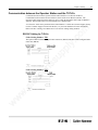
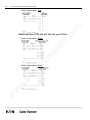
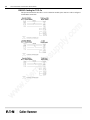
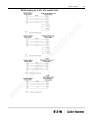
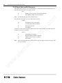
Bit Writes with Ladder Logic – Models 325 and 330
m
The Texas Instrument Hostlink Protocol does not permit an external intelligent device to directly alter
the state of a single bit without overwriting the entire byte in which that bit exists. As a result, the
Operator Station will write to a designated register in the PLC, specifying which bit should be set or
cleared. A section of Ladder Logic Programming is necessary to be written to interpret this value in
order to change the appropriate bit. The starting register that Operator Station will write to is
determined by the register entered in the PLC ID field. If a Bit Write register is not entered, the
register will default to AC677.
y.
co
To set a bit, the bit number will be sent to the Bit Write register. To reset a bit, the bit number
(decimal) + 1000 (decimal) will be sent to the Bit Write register.
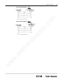
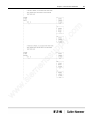
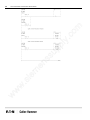
Two rungs of ladder logic will be required for each bit write. Each rung will test the specified register
for the expected value from an Operator Station. If the rung is true, the logic will set or rest a
particular bit as required.
PLC ID
up
pl
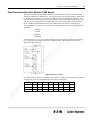
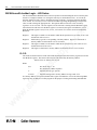
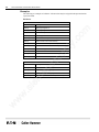
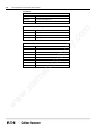
The format for the PLC ID for models 325 and 330 will include both the PLC ID and a memory
register sued for the Bit Write register. The format will be the PLC ID followed by the memory
address.
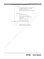
XX-ACYYY or XX-YYY or XX
Where
ss
PLC ID in range 1-90
PLC ID/memory specifier
Optional memory type
Optional starting AC memory address in range 600-677
w
w
w
.s
ie
m
en
XX
AC
YYY