1
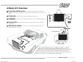
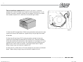
Installation Manual
©
1971-1973 Mustang
DOCUMENT #1-2028
©2012 ClassicAutoAir / 3.12vs.a
CAA 2028 Installation.indd 1
4/2/12 9:57 AM
Congratulations...
You have just purchased the highest quality, best performing
A/C system ever designed for your Classic Vehicle.
To obtain the high level of performance and dependability our systems are known for, please pay close attention to the
following instructions. Our installation steps and procedures are derived from a long history of research and
development and the combined experience achieved thru thousands of successful installations (and feedback from
customers like you). Please remember that our #1 goal is that you’ll have a successful installation and a system that
performs at a very high level for many years to come.
Before starting, read the instructions carefully, from beginning to end, and follow the proper sequence. On the next
page you’ll find a safety and general checklist that you should read before starting your installation.
Again, thank you from our entire staff.
www.classicautoair.com • 866.435.7801
CAA 2028 Installation.indd 3
4/2/12 9:57 AM
4
Check List, Pre-Installation:
Before beginning the installation check the shipping box for the correct components. YOUR BOXED UNIT INCLUDES A LIST OF
MAJOR COMPONENTS AND A LIST OF BAGGED PARTS. We have a 5 stage check process to make sure you have everything you’ll
need.
If your vehicle has been or is being modified, some procedures will need to be adjusted to fit your particular application.
A basic cleaning of the engine compartment and interior before beginning will make things go more smoothly.
Check condition of engine mounts. Excessive engine movement can damage hoses to A/C and/or heater.
Before starting, check vehicle interior electrical functions (interior lights, radio, horn, etc). Make a note of anything that does not work as
it’s supposed to. During the installation you might find the opportunity to repair or upgrade non-working or out of date components.
When you’re ready to start the installation, DISCONNECT THE BATTERY FIRST.
Drain the radiator. Retain the coolant and reuse, or dispose of properly.
SAFETY FIRST: Wear eye protection while drilling/cutting, deburr sharp edges, and never get in a hurry or force a part.
Tools: Your installation only requires the basic tools everyone has in their garage, nothing exotic or specific to A/C or Heat equipment.
Procedures, During Installation:
Fittings: Use one or two drops of mineral oil (supplied with your kit) on ALL rubber o-rings, threads and rear of bump for o-ring where
female nut rides. Do not use thread tape or sealants.
Measure twice (or more), cut once
Should you have any technical questions, or feel you have defective components (or missing items), call us immediately,
we will be glad to assist you. Our toll-free number is listed on every page, we’re here to help!
YOU CAN NOW BEGIN THE INSTALLATION...
www.classicautoair.com • 866.435.7801
CAA 2028 Installation.indd 4
4/2/12 9:57 AM
5
A Basic A/C Overview
OUTSIDE AIR
Evaporator with Blower Fan
1
In order to remove the heat from the air in the vehicle, the A/C
evaporator allows the refrigerant to absorb the heat from the air passing over it. The blower fan moves cool air out into the car
interior.
2
Compressor The compressor pumps and circulates the refrigerant through the system.
3
Condenser The condenser is a heat exchanger mounted at the front of the vehicle. Heat drawn out of the interior of
Suction
Valve Discharge
Valve
the car is expelled here.
4
Receiver/Drier The drier not only dries refrigerant, it also filters the refrigerant and stores it under certain
Receiver
Drier
Condenser
Compressor
operating conditions.
5
High Pressure Switch A pressure switch is used to shut down the system if high or low pressure is
detected, basically it acts as a safety switch.
Firewall
Expansion Valve
AIR FROM INSIDE VEHICLE
COO
LED
AIR
1
SUC
TIO
3
LIQ
UID
NH
OS
HO
SE
E
2
E
ARG
ID SCH
ER
UND
Evaporator Unit
E
HOS
COLD AIR INTO VEHICLE
5
4
GRO
POW
The air conditioning system in your car is comprised of a compressor, condenser,
expansion valve, receiver/drier, and evaporator. Refrigerant (also known as Freon) is
compressed in the compressor and turns into a gas. In the condenser, this gas is cooled to a
liquid state and travels to the expansion valve. As the liquid refrigerant goes through the
expansion valve it rapidly cools in the evaporator. A fan blows over the evaporator and cools the
air that blows out your vents. The receiver-drier separates gas and liquid.
www.classicautoair.com • 866.435.7801 • OVERVIEW
CAA 2028 Installation.indd 5
4/2/12 9:57 AM
6
Control & Operating Instructions
Your new Perfect Fit-Elite system offers complete comfort capabilities in
virtually every driving condition. This includes temperature control in all of the
modes. This system also provides the ability to blend the air between Face,
Heat, and Defrost modes simultaneously. To illustrate the various ways you can
adjust the airflow direction and temperature - we’ve provided these handy
illustrations and chart to show exactly how you can adjust your Perfect
Fit-Elite for maximum comfort...
The FAN switch works like the OEM switch, the DOWN position is OFF
(all power to the system is OFF in this position).
MODE LEVER
There are 11 levels of adjustment within the range of the MODE lever.
The COLD/HOT positions works like any traditional adjustment lever.
FAN SWITCH
NOTE: When the TEMP lever is in the "FULL COLD" position the
compressor is ON, no matter what position the MODE lever is in (think
of it as a compressor-override function).
TEMP LEVER
DASH
Left Lever Postion
Distribution
Compressor State
1
Face A/C
100%
ON
DEF
2
3
4
5
Face
80%
Face
60%
Face
40%
Face
20%
Defrost
20%
Defrost
40%
Defrost
60%
Defrost
80%
6
Defrost
100%
FLOOR
7
8
9
10
Floor
20%
Floor
40%
Floor
60%
Floor
80%
Defrost
80%
Defrost
60%
Defrost
40%
Defrost
20%
11
Floor
100%
ON
WWWCLASSICAUTOAIRCOMs866.435.7801
CAA 2028 Installation.indd 6
4/2/12 9:57 AM
7
INTERIOR
COMPARTMENT
9LTV]L.SV]LIV_*VUZVSLVW[PVUHS
-HJPH9HKPVHUK)LaLSHUKZL[[OLT
HZPKLMVYYLPUZ[HSSSH[LY
ZLLMPN\YL
;OLYLTV]HSVM[OL6YPNPUHS/LH[LY(ZZLTIS`JHUIL
HJJVTWSPZOLKI`KPZJVUULJ[PUN[OYLLJVU[YVSJHISLZ6ULPZ
H[[HJOLK[V[OL/LH[+LMYVZ[KVVYZLLMPN\YL6ULPZ
H[[HJOLK[V[OL;LTWLYH[\YLKVVYHUKVULPZH[[HJOLK[V[OL
=LU[/LH[KVVYZLLMPN\YL+PZJVUULJ[[OLLSLJ[YPJHS
OHYULZZMYVT[OLHZZLTIS`(SZVYLTV]LH[[HJOTLU[ZJYL^
SVJH[LKPUMYVU[VM[OLHPYPUSL[ZLLMPN\YL
FIGURE 1
>OLUYL[HPUPUNWHY[ZP[»ZH
NVVKPKLH[VZ[VYLWHY[ZPUH
aPWSVJRIHNSHILSLK^P[O
GOOD IDEA PUMV^OLYL[OLWHY[ZJHTL
MYVTHUK^OH[ZPaL[`WLVM
[VVSPZULLKLK[VYLPUZ[HSS*SLHUPUN
[OLWHY[ZILMVYL`V\ULLK[VYLPUZ[HSS
[OLTPZHNVVKPKLH[VV
FIGURE 2
FIGURE 3
FIGURE 4
WWWCLASSICAUTOAIRCOMs866.435.7801
CAA 2028 Installation.indd 7
4/2/12 9:57 AM
8
Remove all 4 nuts around blower (as indicated by arrows to right, on passenger
side of firewall). Also disconnect the electrical connector from the blower motor.
Cut wires at grommet in firewall.
Next, remove the OEM defrost duct and set aside for later modification.
DRAIN COOLANT FROM RADIATOR and store safely to reuse or recycle
accordingly. Cut heater hose approximately 1” from firewall. Also, to prevent
forgetting to refill the coolant when the installation is completed, do not put the
cap back into place - instead put the cap to the side and cover radiator hole
with a clean rag or something similar (this will help remind you to add coolant
before starting the engine at the end of the installation).
OEM Heater Unit
(Not reinstalled)
WWWCLASSICAUTOAIRCOMs866.435.7801
CAA 2028 Installation.indd 8
4/2/12 9:57 AM
9
THESE ARE THE PARTS YOU WILL FIND IN BAG KIT A
You will use all of these parts and hardware during the next series of installation steps.
Pressure Switch
(engine compartment)
Ground
Ground
Ground
ECU
Thermostat
OEM Power
Supply
Fan
Plug
&DEOH,QWHJUDWRUV
:LUH+DUQHVV
3RZHU6XSSO\
Blower Switch
Connection
Relay
)DFHSODWH6WLFNHU
%ORZHU6ZLWFK.QRE
%ORZHU6ZLWFK%UDFNHW
%ORZHU6ZLWFK
7ZR[6FUHZV
7ZR&DEOH&OLSV
NOTE: Illustrations NOT shown actual size
WWWCLASSICAUTOAIRCOMs866.435.7801
CAA 2028 Installation.indd 9
4/2/12 9:57 AM
10
Remove The Heater Control Head From The Dash.
1) There are four OEM screws that hold your control head to the dash. Remove
and retain these screws. Remove the control head assembly (see figure 7).
2) Remove the OEM blower switch knob. Retain the screw, you will use it again
shortly. Remove the control cables and the original blower switch and set aside
(these will not be reused, see figure 8).
3) Attach the new blower switch bracket to the top part of the back of the face
plate (see figure 9-10), utilizing the OEM screw, and then attach the blower
switch to the bracket with the two supplied #6 - 20x3/8" screws.
FIGURE 7
(OEM switch
not reinstalled)
FIGURE 8
Retain this
OEM screw
FIGURE 9
Retain all the OEM parts that
you remove, at least until the
installation is completed.
GOOD IDEA
#6 - 20x3/8" Screws
FIGURE 10
WWWCLASSICAUTOAIRCOMs866.435.7801
CAA 2028 Installation.indd 10
4/2/12 9:57 AM
11
Attaching our exclusive
cables to the
control head is accomplished in three easy
steps: Step 1) slide the include cable clips over
the ends of the of the EZ Integrators (as shown
in figure 11) then, Step 2) attach the integrators
to the OEM control head base with the OEM
screw you removed earlier, overlapping the
cable clamps (see figure 12). Step 3) push the
integrator wire ends over the ends of the levers
(see figure 13).
Once you have completed these steps, you
have just one quick task to do before you can
reinstall the control head back into the dash.
We’ve included a new face sticker that
corresponds to the actions of your controls.
Make sure the surface is clean and oil free,
peel off backing and stick the sticker to the
control head face.
MODE
FIGURE 11
l
Contro
ontrol
TEMP C
FIGURE 12
OEM Screw
NOTE: The cable clips will overlap and use
the same hole and the single
OEM screw
Plug in the blower switch, and insert the entire
harness and control head back into dash
opening, resecuring with OEM screws.
FIGURE 13
WWWCLASSICAUTOAIRCOMs866.435.7801
CAA 2028 Installation.indd 11
4/2/12 9:57 AM
12
THESE ARE THE PARTS YOU WILL FIND IN BAG KIT B
You will use all of these parts and hardware during the next series of installation steps.
7ZR[%ROWV
(YDSRUDWRU6XSSRUW%UDFNHW
2QH)UHVK$LU,QOHW%ORFN2II
)RXU[7HN6FUHZV
2QH0DOH6SDGH&RQQHFWRU
'HIURVW+HDW'XFW$VVHPEO\
2QH-&OLS
)RXU[3KLOOLSV6FUHZV
2QH:DVKHU
Illustrations NOT shown actual size
WWWCLASSICAUTOAIRCOMs866.435.7801
CAA 2028 Installation.indd 12
4/2/12 9:57 AM
13
Locate the original wiring harness that supplied power to the original heater
motor (these wires were previously cut on the engine side of the firewall).
Reaching thru the glove box opening pull these wires out of their grommet.
Measure 4” from harness and cut both wires (see figure 15). On the OEM power
supply wire attach a 1/4” insulated male spade connector. Within the OEM fuse
box upgrade the factory HEATER fuse with a 20 amp fuse (VERY
IMPORTANT).
4"
Locate the bottom left mounting hole in the firewall that attached the original
heater motor. From inside of the vehicle drill a 5/8" dia. hole for the drain tube.
TEMPLATE NOTIFICATION! A handy drilling template is included in this
manual (example shown in figure 16).
CAUTION: On the engine side of the firewall there is a brake line. Be
careful not drill through the brake line. It may be necessary to carefully
push this line out of the way, securing it a bit lower is usually all that is
necessary (see figure 17).
FIGURE 15
THIS IS
FROM THE
INSIDE
OF THE
CAR!
All preliminary
modifications to the
vehicle are complete.
YOU CAN DRILL A
SMALL PILOT
HOLE IN THIS
LOCATION FIRST
TECH TIPS
WITH A SMALLER
DRILL BIT (LIKE 3/16"), THEN
PROCEED WITH THE 5/8" BIT
ONCE YOU KNOW YOU HAVE
CLEAR SPACE.
E
KE
LIN
HEATER MOTOR
HOLE
1 3/8"
RA
!B
N
TIO
5/8"
U
CA
FIGURE 16
You can now begin installing your Classic Air Perfect Fit Elite System.
5/8" HOLE
FIGURE 17
WWWCLASSICAUTOAIRCOMs866.435.7801
CAA 2028 Installation.indd 13
4/2/12 9:57 AM
14
Locate the Fresh Air inlet block off. Install over hole in inlet cowl as shown on
the passenger side (see figure 18A). Attach with three #10 - 16 x 3/4" Tek
Screws. Locate the mounting tab location as shown and attach the 1/4" 20
J-clip supplied (see figure 18B).
Install a Fresh Air inlet block off over the vent opening at the drivers-side in the
same way, using the four OEM nuts.
A
Remove evaporator unit from box and place on a flat work surface.
Locate defrost / heat duct assembly and attach to the evaporator using two
#10 - 10 x 5/8" Phillips screws (see figure 19). NOTE: Be sure that the s-clips
are pushed over rear flange on evaporator.
B
Remove ECU from main unit and set aside.
FIGURE 18
Take a minute to familiarize yourself with the evaporator unit:
Actuator Motor
Blower Motor
Bracket
Floor/Face
Vent Door
Evaporator
Support Bracket
Holes
Thermostat
FIGURE 19
Blower Motor Plug
WWWCLASSICAUTOAIRCOMs866.435.7801
CAA 2028 Installation.indd 14
4/2/12 9:57 AM
15
DASH
FIREWALL
Installing the complete evaporator unit under the dash will go much easier with
the help of a friend. One person can take the unit within the car and “roll” up
and under the dash while the other person can be ready at the firewall area with
one of the 1/4" - #20 x 5/8" bolts to secure the unit in place (see figure 20).
Now the unit will be easy to level and secure. Leveling the unit is very important
to insure proper drainage of condensation.
On back side of the evaporator is a mounting bracket with a 1/4"-20 J-clip. This
bracket will go flush with the inside firewall and you will secure the evaporator
by inserting one 1/4" - #20 x 5/8" bolt with a 1/4” washer (from the engine side)
using the bottom right hole (that originally attached the original heater assembly,
see figure 21).
FIGURE 20
LEVEL
TECH TIPS
Be sure to align the evaporator unit level with the bottom of instrument
panel (assuming the vehicle is sitting level) as shown above, but with a small
degree of tilt toward the back to allow proper drain of condensation.
FIGURE 21
1/4 - #20 x 5/8" bolts and
a 1/4” washer
WWWCLASSICAUTOAIRCOMs866.435.7801
CAA 2028 Installation.indd 15
4/2/12 9:57 AM
16
The second 1/4 - #20 x 5/8" bolt attaches the blower motor mounting
bracket in the same location as the original heater mounting in front of the Air
Inlet. The blower support bracket will have an additional hole behind the 1/4 #20 x 5/8" Bolts. Install a #10 - 16 x 3/4" Tek screw through this hole and into
the cowling (see figure 22).
Locate in the Hardware Sack Kit the Evaporator Mounting Bracket and attach
to evaporator unit using two #10 - 10 x 5/8" Phillips screws. Attach other end
to the cowling with a #10 - 16 x 3/4" Tek Screw (see figure 23). IMPORTANT
NOTE: On the side of the main unit you will see several holes for
mounting holes... ONLY USE THE ONES IN THE CENTER FOR THIS
BRACKET! Do not tap into the other holes for any reason (see figure 24).
Also, use a screwdriver and hand-power and do not over-tighten so you
don't strip the holes.
FIGURE 22
#10 - 16 x 3/4" Tek Screw
NO!
YES
FIGURE 24
NO!
FIGURE 23
#10 x 5/8"
Screws
WWWCLASSICAUTOAIRCOMs866.435.7801
CAA 2028 Installation.indd 16
4/2/12 9:57 AM
17
THESE ARE THE PARTS YOU WILL FIND IN BAG KIT C
You will use all of these parts and hardware during the next series of installation steps.
&OHDU3ODVWLF'UDLQ7XEH
(OHFWURQLF:DWHU&RQWURO9DOYH
7ZR&DS3OXJV
6L[:RUP*HDU&ODPSV
7ZR[7HN6FUHZV
5HIULJHUDQW7DSH
)LUHZDOO%ORFN2II
Illustrations NOT shown actual size
WWWCLASSICAUTOAIRCOMs866.435.7801
CAA 2028 Installation.indd 17
4/2/12 9:57 AM
18
Water valve hose connects to this connection
In Bag Kit C you’ll find the firewall block off. Install this over the hose connections
coming thru the firewall within the engine compartment. Attach with two #10 - 16 x
3/4" Tek screws (Figure 25). Seal around the tubes with the included refrigerant tape.
This will keep unwanted moisture and debris from entering thru the firewall... so seal
carefully and thoroughly.
IMPORTANT NOTICE
Classic Auto Air has done extensive testing on the
correct method to install the water valve in order to get a repeatable and progressive
temperature control. The water valve must be installed per these instructions!....
FIGURE 25
The lower connection on the tubes coming thru the block off assembly is going to be
routed to the water outlet on the intake manifold. Attach your hose with cable clamps
on both ends and route where it will not intefere with linkage or come in contact with
exhaust manifolds or headers.
This inlet is
connected
to the intake
manifold
(5
& 2
5(
The upper port coming thru the firewall will be routed to and thru your new your
electronic water valve (the water valve is marked for easy installation). First Attach
a 6” piece of 5/8” dia. heater hose with the supplied worm gear clamp. Attach
to the inlet side of the water valve using another supplied hose clamp.
Attach a heater hose from the outlet side of the electronic water valve
and route to the connection on the water pump.
3 8
03
$7
(5
+(
7
:$
Insert a 6" piece of the clear, 1/2" drain tube we included
through the hole previously drilled and attach over the
drain nipple (see figure 26). Seal around tube with
refrigerant tape.
FIGURE 26
1/2" Clear Drain Tube
Refrigerant Tape
WWWCLASSICAUTOAIRCOMs866.435.7801
CAA 2028 Installation.indd 18
4/2/12 9:57 AM
19
THESE ARE THE PARTS YOU WILL FIND IN BAG KIT D
You will use all of these parts and hardware during the next series of installation steps.
CONT
WATER
VALVE
The ECU will be found
in it’s own box
ROL
LOOR
FACE/F
ST
DEFRO
POWER
)LYH[7HN6FUHZV
<HOORZ
2UDQJH
%OXH
:LUH+DUQHVV6\VWHP
Illustrations NOT shown actual size
CAA 2028 Installation.indd 19
4/2/12 9:57 AM
20
We’ve included enough wire length to allow you to mount the ECU in a variety
of places. It is very important that you mount this in a place where it will stay dry
and that vibration is at a minimum. Also make sure that where ever you mount it
does not interfere with any moving controls or cables. We recommend
mounting it just above the right hand side of the main unit using the included
tek-screws. IMPORTANT! DON’T MOUNT THE ECU PERMANENTLY JUST
YET. THAT CAN BE DONE AFTER YOU CALIBRATE THE UNIT (SEE
NEXT PAGE).
In Bag Kit D you will find three wiring harnesses with connections at each end.
Plug the harness with YELLOW band into the YELLOW ECU port and the other
end into the servo motor on the main unit (motor is marked with YELLOW
INDICATOR). Repeat this process for the other two harnesses, following the
color coding indicated on cables and ports. Attach cable in the engine
compartment to the electronic water valve (see figure 27). Using one of the CAP
PLUGS provided, slot it and install over the heater hose/cable.
INSTALL (2)
1” dia. CAP PLUGS
OVER HOLES.
SLOT ONE FOR THE CABLE.
FIGURE 27
CONT
ROL
DEFROS
FIREWALL
WATER
VALVE
NOTE: The GREEN harness connection will be made from the harness you
previously installed, just plug the loose connection in the CONTROL
port on the ECU.
T
LOOR
FACE/F
POWER
WWWCLASSICAUTOAIRCOMs866.435.7801
CAA 2028 Installation.indd 20
4/2/12 9:57 AM
21
Orang
eH
arn
e
Wiring Diagram/Overview
To 12V Power Supply
Re
Electronic Water Valve
d
/W
ss
hite
Compressor
Wi
re
r
G
Wh
Pressure Switch
Ground
Wire
ite
Blower Switch
r
Ha
n
ee
s
ire
W
e
Blu
s
nes
ECU
Relay
Servo for Defrost Ducts
Blu
eW
ire
Thermostat
Red Wire
ness
ire
W
Blu
e
Servo for Face/Floor Ducts
Blue Har
ss
r ne
Yello w H a
Cable Integrators
Ground
Evaporator
Bl
ue
W ire
Ground
REMINDER: BE SURE THAT THE WIRING HARNESS DOES NOT INTERFERE WITH THE OPERATION OF ANY CONTROLS.
CAA 2028 Installation.indd 21
4/2/12 9:57 AM
22
TEMPORARILY RECONNECT THE BATTERY AT THIS TIME.
MODE
YOU CAN NOW CALIBRATE YOUR UNIT.
CALIBRATION: Before we boxed and shipped your unit, we tested and
calibrated it to factory specifications to make sure it is capable of operating at
maximum efficiency. However, the unit must still be calibrated to your specific
vehicle and controls. This is an easy process that will only take a few minutes.
TEMP
As you follow thru these steps you’ll be able to hear the motors working on your
unit. If for any reason your unit does not calibrate properly the first time, just turn
off the unit and rerun the setup process.
1)
2)
4)
5)
Insert Calibration Key
Move MODE control to the left extreme (DASH) and
TEMP control to right extreme (HOT)
Power Up Board (turn fan control to MEDIUM) the
LED comes ON
After 1 second the LED turns OFF
After 1 second the LED turns ON
B
6)
7)
8)
Move MODE control to other extreme (FLOOR)
After 1 second the LED turns OFF
After 1 second the LED turns ON
C
9) Move TEMP control to other extreme (COLD)
10) After 1 second the LED turns OFF
11) After 1 second the LED turns ON
A
(
(
$/9
(59
:$7
$/9
(59
:$7
\
.H
WLRQ
OLEUD
&D
67
52
'()
17
&2
/
52
&
)$
32
:(
()
/2
25
/
&
)$
52
17
&2
5
32
:(
()
/2
67
52
'()
25
5
\
.H
WLRQ
OLEUD
&D
QUICK
NOTE
3)
Disconnecting the power (i.e. battery) will not cause your ECU to
lose it’s settings. AFTER CALIBRATING, REMOVE KEY AND
STORE IN A SAFE, DRY PLACE - ALONG WITH THIS PAGE.
12) The motor calibration starts, one way
then the other, then the doors set
to midpoint
13) LED turns OFF
14) Turn power to OFF
15) Remove and store calibration key
WWWCLASSICAUTOAIRCOMs866.435.7801
CAA 2028 Installation.indd 22
4/2/12 9:57 AM
23
THESE ARE THE PARTS YOU WILL FIND IN BAG KITS E, F, and G
You will use all of these parts and hardware during the next series of installation steps.
Bag E
'HIURVW$GDSWRU
31
Bag F
Bag G
7ZR/RXYHU$GDSWRUV
31
&HQWHU'DVK9HQW
31
7R&HQWHU
/RXYHU
7ZR'XFW+RVHV,'
&DSSHG
XQXVHG
7R'ULYHUV
6LGH/RXYHU
7ZR'XFW+RVHV,'
)DFH)ORRU
$VVHPEO\
7R3DVVHQJHU
6LGH/RXYHU
)RXU=LS7LHV
)RXU=LS7LHV
)RXU[µ6FUHZV
7ZR'XFW+RVHV
,'
)RXU=LS7LHV
Illustrations NOT shown actual size
XXXDMBTTJDBVUPBJSDPNtt1"(&
WWWCLASSICAUTOAIRCOMs866.435.7801
CAA 2028 Installation.indd 23
4/2/12 9:57 AM
24
Bag Kit E. Locate defrost duct from the heater box to base of the defrost
distribution plenum. Use sharp box knife and carefully trim duct assembly flush
with flange as shown below.
Attach the included defrost adaptor to the duct assembly. Pre-installed S-Clips
will hold it in place.
Attach flex hoses to the adapter and route to the assembly on the top of the
evaporator (see figure 29).
The face/floor assembly comes pre-installed with s-clips which allow you to
install it onto the evaporator unit quickly and securely (see figure 30).
FIGURE 29
FIGURE 30
WWWCLASSICAUTOAIRCOMs866.435.7801
CAA 2028 Installation.indd 24
4/2/12 9:57 AM
25
Attach louver adaptors to the back
side of OEM louvers, both sides.
S-Clips will hold them in place.
Route supplied flex hoses as
shown below. Take your time and
route them so they don’t become
kinked or torn.
TECH TIPS
During installation of the hoses be aware of the eventual movement
of the wiper arm components. Also, the process for installing the
center louver vent will require a small amount of cutting. This is
outlined on the next page.
The smoother the route of the flex hoses
the better the airflow.
GOOD IDEA
OEM VENT
During installation of the hoses be
aware of the eventual movement of
the wiper arm components.
Adaptor
WWWCLASSICAUTOAIRCOMs866.435.7801
CAA 2028 Installation.indd 25
4/2/12 9:57 AM
26
Bag Kit G: Installing the center louver vent requires some cutting to the upper pocket slot in the center dash area. Your goal is to open
the back enough to insert the included center louver unit into the hole and then attach the flex hose. Use a hole drill bit and open it up a
bit at a time (see below). Use the new center louver as a guide to see when you’ve cut-away enough material.
Once the hole is the right size, insert the new center louver and attach the flex hose using ty-wraps to secure. Route to the face/floor
asembly on the evaporator.
FIGURE 32
9LTV]L[OPZ
HYLHRLLWLKNLZ
ZTVV[O
GOOD IDEA
As you cut the hole thru the dash, keep the new center
louver handy and test fit occasionally.
WWWCLASSICAUTOAIRCOMs866.435.7801
CAA 2028 Installation.indd 26
4/2/12 9:58 AM
27
You can reinstall the glove box, radio, bezel, facia and the
console at this time.
This completes the interior portion of the PERFECT
FIT-ELITE installation process. This is a good time to make
a final check that all the controls still move freely and that
nothing is loose or hanging down.
The interior of your car should look pretty much the same as
before you started (or better). Plus you probably got to know
the underside of your dash a lot better and might even have
repaired or upgraded components that needed attention.
Good Job... Let's move on to the major components
within the engine compartment....
If you have any questions before you move
on the final phase of this installation, call us.
888.791.6384
WWWCLASSICAUTOAIRCOMs866.435.7801
CAA 2028 Installation.indd 27
4/2/12 9:58 AM
28
THESE ARE THE PARTS YOU WILL NEED FOR THE
ENGINE COMPARTMENT INSTALLATION
You’ll find all of these parts within the main box
/LTXLG7XEH
/HIW&RQGHQVHU
8SSHU
31
5LJKW&RQGHQVHU
8SSHU
31
/HIW&RQGHQVHU
/RZHU
31
5LJKW&RQGHQVHU
/RZHU
3131
'ULHU%UDFNHW
'ULHU
/LTXLG7XEH
'ULHUWR(YDSRUDWRU
&RQGHQVHU
31
'LVFKDUJH7XEH
&RUH6XSSRUW6SDFHU
µ
R V H
Q+
WL R
XF
)RXU=LS7LHV
)RXU[7HN6FUHZV
6SOLFHDQG
%XOOHW&RQQHFWRU
3UHVVXUH6ZLWFK
%DJRI2ULQJVDQG0LQHUDO2LO7XEH
/LTXLG+RVH
'
LVFKD
UJH+RV
H
3UHVVXUH6ZLWFK+DUQHVV
7XEH6XSSRUW%UDFNHW
31
6
7HQ[+H[6FUHZV
7KUHH5HIULJHUDQW+RVHV
WWWCLASSICAUTOAIRCOMs866.435.7801
CAA 2028 Installation.indd 28
4/2/12 9:58 AM
29
ENGINE COMPARTMENT
INSTRUCTIONS
ENGINE
COMPARTMENT
FIRST THING: IF YOU HAVE NOT
DONE SO ALREADY, DISCONNECT
THE BATTERY.
During the next steps you’ll be installing the condenser, drier,
and routing the high/low pressure lines and the liquid line.
Since much of this is installed in the OEM location for the
condenser, you’ll need to remove the center grill section, and
latch support assembly (see figure 33). Be sure to retain all the
mounting screws – you’ll reinstall these pieces in the exact
reverse order with the OEM screws.
FIGURE 33
WWWCLASSICAUTOAIRCOMs866.435.7801
CAA 2028 Installation.indd 29
4/2/12 9:58 AM
30
DRIER AND CONDENSER PREPARATION. You can perform most of the
following steps on a clean flat surface like a workbench. Lay the condenser
down so that both hose connections are on the right side (the larger connection
will be on top). We’ve provided four brackets, 2 upper and 2 lowers, each
designed to mounted to the correct side of the condenser. Use the diagram
below to install the brackets in the correct places (plus, once you slide the
condenser into place in the car, the bolt holes on the brackets will align to the
OEM holes in the support, so you can adjust if necessary).
Use the #10 x 3/8” screws to mount the brackets to the
condenser.
TECH TIPS
You can easily find the
correct position for mounting
the drier to the condenser by
using the drier liquid tube as
a gauge.
Install the drier on the right hand side of the condenser.
First insert the drier into the drier mounting bracket (it’s
basically a sleeve for the drier). Attach the drier liquid tube
to the drier and also to the connection on the lower
condenser (tighten connections at either end using
supplied o-rings on both ends and a few drops of mineral
oil to each o-ring). With these two components combined
it will easy to find the correct place to attach the drier
bracket to the condenser with the included tek screws.
Place the condenser into place in the vehicle. Secure
brackets to holes in OEM support with included Tek
screws.
TECH TIPS
Reminder...
Use two
wrenches to
tighten o-ring
fittings
WWWCLASSICAUTOAIRCOMs866.435.7801
CAA 2028 Installation.indd 30
4/2/12 9:58 AM
31
Screw the high-pressure switch into the port at the top of the drier. Plug in harness.
Just to the left of the hole that you will route the tubes thru the support is a
dimple (see illustration to the right). Drill a 3/16” hole thru the dimple, and mount
the included tube support spacer.
Locate the Liquid Tube, and the Discharge Tube. Using (1) #6 o-ring and a few
drops of mineral oil attach liquid tube to drier and pass through the opening in the
radiator core support. Using (1) #8 o-ring and a few drops of mineral oil attach
discharge tube to the condenser and pass through the opening.
Attach bracket over tubes. Insert screw through bracket, spacer and then through
previosly drilled hole. Attach using the #10 nut.
Spacer
Route wires from high-pressure switch out thru the tube hole and along the
discharge tube into the engine compartment.
Bracket
WWWCLASSICAUTOAIRCOMs866.435.7801
CAA 2028 Installation.indd 31
4/2/12 9:58 AM
32
rS
de
Fe
n
CO
COMMPLETE
PRES
KIT SOR
tru
ts
Time to install the compressor kit. Included in your box is a premium
compressor kit with all the parts you’ll need to install the compressor. This kit
includes instructions specifically written for your engine. Once you’ve installed
the complete compressor kit, continue on to connecting the hoses.
FIGURE 37
1) Attach the #8 Discharge Hose (13/32") to the connection coming thru the core
support and route to the compressor. Tighten fittings using o-rings and mineral
oil provided.
2) Attach the #6 liquid hose (5/16") to the connection coming thru the core
support and route along the underside of the fender struts, around the engine,
and to the connection at the firewall on the evaporator unit (see figure 41). Using
supplied zip-ties you’ll attach this hose, the suction hose and the lead from the
high pressure switch to the strut braces, securing all three at once. Tighten
fittings using o-rings and mineral oil supplied in kit.
3) Attach the #10 suction hose (1/2”) to the compressor and route as mentioned
above. Tighten fittings using o-rings and mineral oil supplied in the kit.
WWWCLASSICAUTOAIRCOMs866.435.7801
CAA 2028 Installation.indd 32
4/2/12 9:58 AM
33
New A/C System Preparation
Please read thru these procedures before completing this new A/C system charging
operation. A licensed A/C technician should be utilized for these procedures to insure that
your new system will perform at it’s peak, and that your compressor will not be damaged.
1) Your radiator/cooling system is an integral part of your new system. Please insure that you
have a 50/50 mix of distilled water and antifreeze. The heater coil MUST be purged
(cycle heater control valve) to make sure no water, without antifreeze, is in the heater coil
before you charge the A/C system.
2) Evacuate the system for 45 minutes (minimum).
3) Your new compressor MUST be hand-turned 15-20 revolutions before and after
charging with liquid. Failure to do this may cause the reed valves to become damaged (this
damage is NOT covered by your warranty).
4) Your new system requires 134a refrigerant. It will require 1.5 lbs (or 24 oz).
5) Your new compressor comes charged with oil - NO additional oil is needed.
6) Insure that the new belt is tight.
7)
DO NOT CHARGE SYSTEM WITH LIQUID WHILE THE ENGINE IS RUNNING!
RECOMMENDED TEST CONDITIONS: (After system has been fully charged and tested for basic
operation)
• Determine the temperature outside of the car
• Connect gauges or service equipment to high/low charging ports
• Place blower fan switch on medium
• Close all doors and windows on vehicle
• Place shop fan directly in front of condenser
• Run engine idle up to approx. 1500 rpm
ACCEPTABLE OPERATING PRESSURE RANGES:
1. HIGH-SIDE PRESSURES (150-250 PSI)
2. LOW-SIDE PRESSURES (15-25 PSI in a steady state)
Centerline of the Oil Plug
90˚
90˚
CAUTION! When mounting your compressor
and/or adjusting the belt, use caution not to tilt the
compressor up to or more than 90˚ off the
centerline of the oil fill plug. This can cause
compressor failure.
Do not tilt, shake or turn
refrigerant can upside-down
OR use a charging station to
install refrigerant while the
engine is running. Doing so will
direct liquid refrigerant into the
compressor piston chamber, causing damage to
reed valves and/or pistons and/or other components, as
well as potentially seizing the compressor. Allow a
minimum of 30 minutes for liquid to "boil off.” You must
hand turn the compressor hub (not the pulley) a minimum
of 15 complete revolutions prior to starting the engine
with the clutch engaged.
Readings above are based on an ambient temperature of 90˚ with an adequate airflow on condenser
www.classicautoair.com • 866.435.7801
CAA 2028 Installation.indd 33
4/2/12 9:58 AM
34
Trouble Shooting Your Classic Auto Air A/C System
PROBLEM: system is not cooling properly
ISSUE: cold at idle, warmer when raising engine RPM’s
Make sure the Water Valve is positioned correctly
The water valve is a directional valve and should be installed with the arrow pointing
towards the water pump, it should be connected to the heater hose that runs from the
heater core to the water pump. If the water valve is connected to the incorrect hose it
allows water to circulate through the system via the heater core over powering the
cooling effect of the A/C coil, (normally the air conditioning is functioning properly).
Step 1: Check placement of the water valve, correct if needed. (In some cases
changing the location of the water valve may not fix the above problem.) Continue to
next step.
Step2 If changing the location of the water valve does not rectify the issue, then
possibly the water valve is permenatly damaged and may need to be replaced. To
check the integrity of the water valve completely remove the water hoses for the
heater core and “loop” together. (This will remove the heater system completely from
the possibilities) If the system now cools, replace the water valve
Verify Adequate Air Flow to Condenser
For an air condiitiong system to function properly there has to be adequate airflow
across the condenser. The function of the condenser is to disapate heat, without
proper airflow your system will not cool correctly in the cabin of your vehicle.
Step 1: connect gauges to a/c hoses. The pressures should be: with the ambient
temp is 90, low side pressures should be between 8-25 psi, high side pressures
should be between 160-260psi
Step 2: IF the low side pressures are normal and the high side pressures are high
then there might be an airflow issue, continue to next step.
3.
With car still in idle and gages attached, pour water down the front of the
condenser. What happens to the pressures?
If the paper is held in place you are at least getting some air flow. If the high side
decreases during test 2 & 3 then your condenser is not getting enough air which is
causing your system to not cool properly. To correct this issue you will need a more
powerful mechanical fan.
Step 3: Confirm correct Refrigerant charge in System
All of our systems should be charged with 24oz or 1.8lbs of R134 Refrigerant only. If
overcharged you will need to evacuate the system and recharge with the correct
amount.*
What measurements mean:
Low Temp and High Pressure seem to be equal...
You have a malfunctioning expansion valve that is stuck open.
High Side is extremely high and Low Side is extremely low (possibly into
vacuum)...
There is a blockage in the system. Remove hoses and blow compressed air through in
both directions. If pressures don’t change its possible that your expansion valve is
stuck closed and would have to be replaced.
*Compressor Concerns:
This is often misdiagnosed as a problem for the system not cooling properly. If you
have a noisy compressor it is due to improper charging of refrigerant. An overcharged
(more than 24oz or 1.8lbs R134) compressor can cause rattling. If charged with pure
liquid there is a high probability you have bent reed valves that are causing tapping
sound.
To test air flow to Condenser do the following three tests:
1. Place a piece of paper on the condenser with the car in idle and see if paper is
held in place.
2. With car in idle, attach gages, and place a large capacity fan in front of the
condenser. What happens to the pressures?
www.classicautoair.com • 866.435.7801
CAA 2028 Installation.indd 34
4/2/12 9:58 AM
35
TROUBLESHOOTING GUIDE
TEST CONDITIONS USED TO DETERMINE SYSTEM OPERATION
(THESE TEST CONDITIONS WILL SIMULATE THE AFFECT OF DRIVING THE VEHICLE AND
GIVE THE TECHNICIAN THE THREE CRITICAL READINGS THAT THEY WILL NEED TO
DIAGNOSE ANY POTENTIAL PROBLEMS).
B. CONNECT GAUGES OR SERVICE EQUIPMENT TO HIGH/LOW
CHARGING PORTS.
C. PLACE BLOWER FAN SWITCH ON MEDIUM.
D. CLOSE ALL DOORS AND WINDOWS ON VEHICLE.
E. PLACE SHOP FAN IN FRONT OF CONDENSER.
F. RUN ENGINE IDLE UP TO 1500 RPM.
ACCEPTABLE OPERATING PRESSURE RANGES (R134A TYPE)
1. HIGH-SIDE PRESSURES ( 160-250 PSI ) *Note- general rule of thumb is
two times the ambient (daytime) temperature, plus 15-20%.
2. LOW-SIDE PRESSURES ( 06-22 PSI in a steady state).
CHARGE AS FOLLOWS: R134A = 24 OZ.
NO ADDITIONAL OIL IS NECESSARY IN OUR NEW COMPRESSORS.
TYPICAL PROBLEMS ENCOUNTERED IN CHARGING SYSTEMS
NOISY COMPRESSOR. A noisy compressor is generally caused by charging a
compressor with liquid or overcharging
A. If the system is overcharged both gauges will read abnormally high readings.
This is causing a feedback pressure on the compressor causing it to rattle or
shake from the increased cylinder head pressures. System must be evacuated
and re-charged to exact weight specifications.
B. Heater control valve installation - Installing the heater control valve in the
incorrect hose. Usually when this occurs the system will cool at idle then start
to warm up when raising the RPM’s of the motor. THE HEATER CONTROL IS
A DIRECTIONAL VALVE; MAKE SURE THE WATER FLOW IS WITH THE
DIRECTION OF THE ARROW. As the engine heats up that water transfers the
heat to the coil, thus overpowering the a/c coil. A leaking or faulty valve will
have a more pronounced affect on the unit’s cooling ability. Installing the valve
improperly (such as having the flow reversed) will also allow water to flow
through, thus inhibiting cooling. Check for heat transfer by disconnecting
hoses from the system completely. By running down the road with the hoses
looped backed through the motor, you eliminate the possibility of heat transfer
to the unit.
C. Evaporator freezing - Freezing can occur both externally and internally on
an evaporator core. External freeze up occurs when the coil cannot effectively
displace the condensation on the outside fins and the water forms ice (the
evaporator core resembles a block of solid ice), it restricts the flow of air that
can pass through it, which gives the illusion of the air not functioning. The
common cause of external freezing is the setting of the thermostat and the
presence of high humidity in the passenger compartment. All door and
window seals should be checked in the event of constant freeze-up. A
thermostat is provided with all units to control the cycling of the compressor.
D. Internal freeze up occurs when there is too much moisture inside the
system. The symptoms of internal freeze up often surface after extended
highway driving. The volume of air stays constant, but the temperature of the
air gradually rises. When this freezing occurs the low side pressure will drop,
eventually going into a vacuum. At this point, the system should be checked by
a professional who will evacuate the system and the drier will have to be
changed.
E. Inadequate airflow to condenser - The condenser works best in front of
the radiator with a large supply of fresh air. Abnormally high pressures will
result from improper airflow. Check the airflow requirements by placing a large
capacity fan in front of the condenser and running cool water over the surface.
If the pressures drop significantly, this will indicate the need for better airflow.
F. Incorrect or inadequate condenser capacity - Incorrect condenser
capacity will cause abnormally high head pressures. A quick test that can be
performed is to run cool water over the condenser while the system is
operating, if the pressures decrease significantly, it is likely a airflow or
capacity problem.
G. Expansion valve failure - An expansion valve failure is generally caused by
dirt or debris entering the system during assembly. If an expansion valve fails
it will be indicated by abnormal gauge readings. A valve that is blocked will be
indicated by high side that is unusually high, while the low side will be
www.classicautoair.com • 866.435.7801
CAA 2028 Installation.indd 35
4/2/12 9:58 AM
CAA 2028 Installation.indd 36
4/2/12 9:58 AM
OEM
HOLE
DRILL 5/8’
HOLE
THIS IS FROM
THE INSIDE
OF CAR!
1971-1973
TEMPLATE
DRILL 9/32’ HOLE
CUT 4” DIAMETER HOLE
OEM
HOLE