1
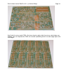
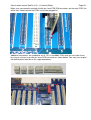
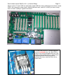
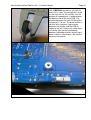
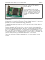
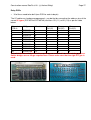
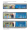
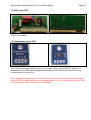
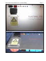
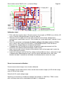
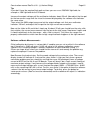
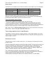
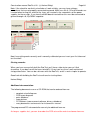
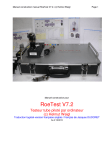
Construction manual RoeTest V8 - (c) Helmut Weigl
Page 1
Construction manual for
RoeTest V8
professional tube testing system
(c) Helmut Weigl
much thanks for english translation to Ton Regeling, USA
and Spence Barton, USA
As of: 01/2015
Construction manual RoeTest V8 - (c) Helmut Weigl
Page 2
Table of contents
Introduction to this manual ............................................................................................................................ 3
Disclaimer:.................................................................................................................................................... 3
Copyright: ..................................................................................................................................................... 4
Hardware Revision History: ........................................................................................................................... 5
RoeTest4 – changes compared to RoeTest3: ............................................................................................ 5
RoeTest V5 to RoeTest4: .......................................................................................................................... 5
Changes RoeTest V6 to RoeTest5:............................................................................................................ 6
Changes V6.2 to V6:.................................................................................................................................. 6
Changes V7 to V6.2................................................................................................................................... 7
Changes V7.2 to V7................................................................................................................................... 7
Functional description: .................................................................................................................................. 8
Block diagram:........................................................................................................................................... 9
Circuit description: ................................................................................................................................... 10
Boards:.................................................................................................................................................... 12
Component selection: ................................................................................................................................. 13
PCBs: ......................................................................................................................................................... 16
PCB construction: ....................................................................................................................................... 19
Socket box receiver – mechanical construction: .......................................................................................... 31
Housing/cabinet: ......................................................................................................................................... 37
Wiring: ........................................................................................................................................................ 52
First time power on / test procedure: ........................................................................................................... 53
Constant voltages.................................................................................................................................... 55
Variable/microcontroller controlled output voltages:.................................................................................. 55
Calibration of the 600V board: ................................................................................................................. 57
Calibration of the voltage measurement ranges: ...................................................................................... 57
Calibration of 600V measurement range on G3 card (from version 6 onwards):........................................ 58
Calibration of the heater voltage measurement: ....................................................................................... 58
Current measurement calibration: ............................................................................................................ 60
Current limiter:......................................................................................................................................... 63
To test voltage regulation of the H, A and G2 boards: .............................................................................. 63
Test check for continuity circuits: ............................................................................................................ 63
Closing remarks: ......................................................................................................................................... 64
Construction manual RoeTest V8 - (c) Helmut Weigl
Page 3
Introduction to this manual:
Building the RoeTest tube tester is not a project for beginners. In addition to the size and
complexity of the project, this tube tester works with high and lethal voltages. Experience
is required. I recommend that you only try to build this tester if you have ample knowledge
of and experience with electronics.
That said, the tube tester can be built successfully as shown by the many testers built by
other people. You can see these on the website. The manuals appear to be
complete and correct, I would be grateful if you would let me know if you find errors in
the manuals or if you have improvement suggestions.
Disclaimer:
THE ROETEST CIRCUIT DESIGNS, HARDWARE, SOFTWARE OR ANY OTHER MATERIAL ARE PROVIDED
BY ME ''AS IS'' AND ANY EXPRESS OR IMPLIED WARRANTIES, INCLUDING, BUT NOT LIMITED TO, THE
IMPLIED WARRANTIES OF MERCHANTABILITY AND FITNESS FOR A PARTICULAR PURPOSE ARE
DISCLAIMED. IN NO EVENT SHALL I BE LIABLE FOR ANY DIRECT, INDIRECT, INCIDENTAL, SPECIAL,
EXEMPLARY, OR CONSEQUENTIAL DAMAGES (INCLUDING, BUT NOT LIMITED TO, PROCUREMENT OF
SUBSTITUTE GOODS OR SERVICES; LOSS OF USE, DATA, OR PROFITS; OR BUSINESS INTERRUPTION)
HOWEVER CAUSED AND ON ANY THEORY OF LIABILITY, WHETHER IN CONTRACT, STRICT LIABILITY,
OR TORT (INCLUDING NEGLIGENCE OR OTHERWISE) ARISING IN ANY WAY OUT OF THE USE OF THE
CIRCUIT DESIGNS, HARDWARE OR SOFTWARE, EVEN IF ADVISED OF THE POSSIBILITY OF SUCH
DAMAGE.
The building of a RoeTest is undertaken at your own risk. Software, especially, is never fault
free, and can lead to a malfunction.
Lethal and high voltages:
Tubes and tube testers including the RoeTest work with high and lethal voltages.
Please note that working with high voltages is dangerous. The voltages in the tube
tester and also on the tube sockets pins are dangerous and can lead to injury or death.
Use with care. Ensure the RoeTest is only used by adults with knowledge of vacuum
tubes and electronics. Keep away from children and animals. You and anyone using the
tube tester are responsible for making sure you meet all the nationwide and local safety
regulations.
Please remember that charged capacitors, in a power supply, will remain
charged to high voltages for a long time after being switched off or disconnected from the
mains, despite the use of bleeder resistors. Please discharge these capacitors with a
suitable resistor before working on or experimenting with the circuits!
The RoeTest is a do-it-yourself (DIY) project. The RoeTest is not UL/CE/GS/Tüv tested or
listed and I cannot guarantee that use of the RoeTest is legal or permitted.
Changes may be made to the software or hardware at any time. Compatibility with earlier
versions is not guaranteed, even when current versions are compatible with earlier versions.
Construction manual RoeTest V8 - (c) Helmut Weigl
Page 4
Note related to the tube data database:
The extensive tube data database is constantly changing. Tube data is added, changed and/or
deleted. Current tube data may be wrong or incomplete. No warranties are provided as to the
completeness and/or correctness of the tube data. The database does contain data for tubes
that the RoeTest cannot test, either because the required voltages or currents are too high or
because they are for certain tubes for special applications.
Copyright:
Copyright Helmut Weigl, Heidestr. 7, 92708 Mantel, email [email protected]. I maintain all
rights to the hardware, hardware designs and software. The software, hardware designs or
any other material remain my intellectual property. You merely obtain a license to use the
hardware designs, software or any other material for private use only.
The database is made available for private use only and changing the data structure
or removing copyrights is prohibited. Use of the contents of the database for any other
application than the RoeTest tube tester is prohibited.
Commercial usage is allowed only with written permission from me. Testing tubes for sale
is permited, but the sale my software or documentation and the building 'RoeTest' tube testers
or components for sale is prohibited.
Printed Circuit board (PCB) designs and layouts may be changed for your own purposes
and use. You are not allowed to give or sell the PCB designs and layouts to third parties
without my consent. You may only send these to a PCB manufacturer for the purpose of
ordering PCBs for your own use. The sale of PCBs from my designs is prohibited.
The firmware for the PIC-Microcontroller can only be obtained from me, in the form of a
preprogrammed PIC Microcontroller chip. Copying and distribution of the software and
firmware is prohibited. The!read-only protection of the microcontroller firmware may not be
disabled in any way.
When you print the results of tests made with the RoeTest, you may not remove the copyright
marks.
Many of the socket images used by the RoeTest software are provided by Mr. Franz
Hamberger. Mr. Hamberger makes these images available for private use on his website. The
internet address for Mr. Hamberger’s website is:
http://www.dl7avf.info/charts/roehren/index.html.
Distribution of these images is only allowed under the conditions described on Mr.
Hamberger’s website.
.
Construction manual RoeTest V8 - (c) Helmut Weigl
Page 5
Hardware Revision History:
RoeTest4 – changes compared to RoeTest3:
The Roetest4 has the same functions as the RoeTest3. The circuits to supply the test voltages
have changed. The following has changed:
New circuit: electronic stabilization of the voltage supplies under load. Software
compensation is no longer required.
Simpler calibration of the voltage supplies.
The +/- 2.5 V voltage supplies are no longer required.
Special transformers are no longer required, low cost standard transformers can now be
used.
The main transformer has less windings.
Maximum heater current is increased to 5 A (in the 12.75V range).
The PCB layouts were redesigned requiring less patch wires.
The USB interface is now on the main PCB such that just a small USB connector board is
needed.
My prototype is constructed differently – the main PCB is split in two PCBs and housed in a
compact cabinet with transparent sides.
The goal was to improve the circuits, to reduce the effort to build the RoeTest and to
decrease the need for special parts. Now standard, low cost and readily available parts other
than the main transformer and the tube sockets are used.
Also a few more components had to be placed on the test voltage PCBs. Especially the heater
voltage PCB is densely populated. A small solder iron and some patience helps when putting
it together. The main PCB was laid out in such a way that it can be manufactured as one piece
(40 x 20 cm) or as two pieces (2 x 20 x 20 cm).
RoeTest V5 to RoeTest4:
The G1 and G3 boards are completely redesigned. Instead of a high voltage opamp built
with discrete components a high voltage opamp IC is used.
The G3 board has an additional circuit for measuring high voltages, that is for instance
used when testing voltage stabilizers.
Completely redesigned circuits for the plate, G2 and heater supply boards. Voltages are
controlled by an integrated precision opamp, instead of an opamp built using discrete
components.
The USB power is now supplied using a relay, such that no current flows when the
RoeTest is switched off. When the RoeTest is switched on power is supplied to the USB
chip using the relay to enable the USB interface.
The 600V plate voltage circuit is redesigned and is put on a separate PCB
Small layout changes in the other PCBs.
Use of a different PIC Microprocessor with 12 bit A/D converters (before 10 bit A/D
converters were used).
New firmware.
The software is modified to support the new design and is compatible with earlier versions.
The new circuit designs allow for more accurate measurement and test results.
Construction manual RoeTest V8 - (c) Helmut Weigl
Page 6
Changes RoeTest V6 to RoeTest5:
Circuit designs stayed largely the same. The goal was to simplify the construction of the
RoeTest. To accomplish that, the following changes were made:
1. New double-sided PCB. The transformer PCB and connector PCBs are now integrated
with the main PCB. Even more wire patches are removed. The only remaining board
connections are the mains power, mains transformer, connection to the MOSFETs and to
the tube socket station. This reduces the number of hours required to build the RoeTest
and reduces the probability of errors.
2. The microprocessor PCB is now also double sided. All the other PCBs remain single sided.
There are only a few remaining wire patches required (on the heater board).
3. A chassis is no longer required. Instead, the main PCB and the main transformer can now
be screwed to the backside of a stabile aluminum front panel. The front panel can then be
put into an applicable cabinet such as an aluminum suitcase or table cabinet.
4. A front panel design is now available, made with Front Panel Designer. If you are not able
to or don’t want to make your own front panel you can now use the design to order one
from Front Panel Express, Inc (the US branch of the Schaeffer company in Germany).
5. The front panel is also used as the heat sink for the MOSFETs. A separate heat sink is no
longer required. Small tubes can now be tested continuously, if you are testing larger tubes
you’ll have to monitor the temperature and if needed wait in between testing tubes or
alternatively you can use a fan for extra cooling.
There are a few downsides: with the new large main PCB you have less flexibility in choosing
or constructing a cabinet for the tube tester. The large double-sided PCB is probably too
complex to make yourself. If you like to make your own PCBs or if you want more flexibility
with constructing a cabinet you can still use the RoeTest 5 main PCB designs. The main PCB
V5 is compatible with the other V6 PCBs.
Changes V6.2 to V6:
No changes in circuit design. A few PCB layout errors were fixed. Also a few small changes
were made:
1. Banana jacks are now mounted on the main PCB. No external wiring needed.
2. The wire connections to the tube socket boxes are now soldered directly on to the bottom
side of the main PCB, leading to even shorter connections.
Construction manual RoeTest V8 - (c) Helmut Weigl
Page 7
Changes V7 to V6.2
1. Change of layout such that no wire connections to the MOSFETs are needed, the
MOSFETS are now soldered on the main PCB. This required a change to the main PCB
and the plug-in PCBs.
2. The plug-in PCBs for the heater, anode, G2 and 600V boards now have additional contacts
3. Temperature management: you can now optionally connect a temperature sensor to the
heat sink to control a fan. The software can now turn on the fan if the temperature gets too
high. The heat sink can be smaller and yet there’s more margin.
4. The +320V and -68V voltages are now regulated using a LR8 supertex voltage regulator
such that the circuit is now simpler.
5. PCB layout improvements, especially ground connections have been overhauled.
6. New version 7 firmware, compatible with hardware version 5 and higher.
Changes V7.2 to V7
1. optimization of the layout – shorter wires
2. new Firmware 7.2 (compatible with hardware from V5)
Changes V8 to V7.2:
1 A reduction in size of the motherboard. This is only 39 cm long and fits just in a steel
housing with 40 cm length.
2 Due to the shorter motherboard we're again saved a few cm wire length.
3 For the fixed 320V supply, the previous 4 transformers were replaced by two transformers
and configured as a voltage doubler (saves board space)
4 The G1 + G3 voltages now go to -63 V (previously-51V)
5 The measuring range for heater current is now extended to 6.1 A (previously 5.1 A). The
larger measurement range can show in-rush current better. The long term current capability of
5A has not changed (only for brief periods currents of 5.5A are allowed). Only the measuring
range has been increased.
6 The measuring range for anode current is now extended to 300 mA. The continuous current
capability is still 250 mA (300 mA for short periods is allowed). With the change, short peaks
are displayed. This gives an advantage in the recording of characteristics. For short-period,
high current flows the curves measured with V8 now display up to 300 mA.
7 The measuring range for G2-current is now extended to 60 mA. The continuous current
capability of 50 mA (60 mA is only briefly allowed) has not changed. With the changes in V8,
short peaks up to 60mA are displayed. The advantage is in the recording characteristics: For
short period high current flows, tests and curves made with V8 may display up to 60 mA.
8 600V Card: New circuit with control (so far only stabilization). The voltage at the load is thus
ultra-stable (as with the other cards). Another advantage is that the components on the card
stay cool (previously a small amout of power was wasted minimum load of the voltage
regulator).
9 Adapter board for USB chip. Now soldering the tiny USB chip to the motherboard loses its
Construction manual RoeTest V8 - (c) Helmut Weigl
Page 8
terror. In a failed attempt you can just use another adapter board, no damage to the
motherboard.
10 More ground trace surface. Soldering on additional copper wire to carry high current is no
longer needed
11 Better RF attenuation elements on socket box receiver. This means that in most cases no
ferrite beads are required in the socket boxes themselves.
Functional description:
The RoeTest employs a USB interface to connect to a PC. A PIC microcontroller receives
commands from the PC software and executes these. The PIC microcontroller controls the
output voltages of the heater (H), anode a.k.a. plate (A), G1, G2 and G3 boards and a matrix
of relays to connect tube pins to a voltage source. The PIC continuously measures voltages
and currents and sends these back to the PC software for display and analysis. The PIC also
supports functions such as checking for continuity and controlling external heater voltage
relays. To be able to increase the anode voltage there is a 600V board, which is a constant
300V voltage source, connected in series with the anode voltage board.
Construction manual RoeTest V8 - (c) Helmut Weigl
Page 9
Block diagram:
The 5 voltage sources can be recognized in the block diagram. The 5 voltage sources and
ground are connected to 6 rails. The tube pins are then connected to the rails using a matrix of
relays. The relay matrix consists of 10 cards each with 6 relays. In addition, on the
motherboard, are supplies for +5V, +/-12V, -68V, +320V and +12V (unstabilized, for the
relays) for the various circuits.
Construction manual RoeTest V8 - (c) Helmut Weigl
Page 10
Circuit description:
Supply voltages:
The relay voltage is not stabilized.
The +5 and +/- 12V sources need to be very stable and for that reason precision voltage
regulators with low temperature drift are used. The absolute voltage output is less important
than the stability since voltage variations would result in measurement errors.
The additional +320V and -68V sources are stabilized using an LR8.
Variable voltage sources for the heater, anode (plate) and G2 voltages:
These all function in a similar manner, as shown in the following simplified diagram:
A D/A converter that is connected to the I²C-Bus is controlled by the PIC and generates a 0 to
5V voltage and that voltage is amplified to over 300V using an opamp and a transistor.
The output is connected to a voltage divider around RV and the voltage measured at that point
is fed back to a differential amplifier. This differential amplifier compares the voltages on the +
and – inputs of the differential amplifier and keeps the output voltage constant (feedback loop).
To make the circuit stable many circuit updates needed to be made so the real circuit has
quite a few more parts.
Construction manual RoeTest V8 - (c) Helmut Weigl
Page 11
Additionally each PCB has a few relays to switch various ranges.
The H, A and G2 circuits use MOSFETs for increased power output.
Finally the H, A and G2 circuits have a current limiter circuit: if the voltage drop over a resistor
exceeds about 0.6 volts, a transistor is switched on to decrease the MOSFET output voltage
such that the output current is limited.
Here is some more detail, please refer to the actual circuit diagrams (these are on a CD-ROM
can be obtained from me):
A voltage divider circuit is used to measure the voltage outputs of the voltage boards, and that
voltage is fed into an opamp whose output is connected to an A/D converter input on the PIC
microcontroller.
H, A and G2 output current is measured by measuring the voltage drop over resistors in the
ground connections between the input voltage sources and central ground. For that, current is
supplied by separate transformer circuits. Opamps are used again as amplifiers for the
measured voltages and the output voltage is connected to an A/D converter input on the PIC
microcontroller (see detailed circuit diagrams).
Board component dimensions and layout are different for each board. Where needed, relays
are used to switch measurement ranges. This allows for high resolution even in the low ranges
for voltage output control and output voltage and current measurement. For the heater circuit
low-high ranges, also the transformer circuit and current limiter resistors are different.
Each board has a relay to connect the output to a relay matrix rail. The G2 board can also be
connected over two 470K resistors to a rail, for testing magic eyes. The G1 board can be
connected to a rail over a 1.2M resistor for tube vacuum testing. Relays are controlled by the
PIC microcontroller by using relay drivers on the PIC PCB or for the relay matrix cards by relay
drivers on the relay matrix PCBs connected to the I²C-Bus.
LEDs and discharge resistors are used to discharge the electrolytic capacitors when the tube
tester is switched off. The LEDs indicate whether the resistors are still charged with a high
voltage. For safety reasons you should only work on the tester when all electrolytic capacitors
are discharged. The main PCB has various connection points that allow you to quicker
discharge these capacitors e.g. using a light bulb, or that allow you to measure the voltage
levels to verify the capacitors are discharged.
A high voltage opamp (OPA445A) is used for the G1 and G3 boards. MOSFETs are used to
increase output power. See detailed circuit diagrams.
The G3 card also has a circuit to measure high voltages, and the circuit is active when the G3
card is not used for generating the G3 voltage. This is used e.g. when testing voltage
stabilizers.
Construction manual RoeTest V8 - (c) Helmut Weigl
Page 12
Boards:
There is a PCB for each of the 5 voltage sources. There is also a PCB for the PIC
microcontroller (with relay drivers) and a PCB for the 600V range. Finally there are 10 PCBs
for the relay matrix, each with relay drivers.
These PCBs are connected to and inserted in the main PCB.
The main PCB has the following circuits:
Supply voltages
Fuses and rectifiers, and the filter capacitors for the H, A, G2- voltage and 600 V boards
Continuity checkers
Relays to switch to an external heater voltage source
USB interface
Soft start for the toroid transformer using an NTC and relay.
Construction manual RoeTest V8 - (c) Helmut Weigl
Page 13
Component selection:
I recommend using only first class components. If you’re using second class components you
should expect second class quality.
For tube sockets I recommend you use socket boxes and not to have fixed sockets.
Transformers:
For +/- 12-V, relays and other voltages normal standard transformers are used.
For the -68V supply a 2 x 24V transformer will do. Since the load is minimal, the idle (no load)
voltage is high enough.
Fixed +320 V supply: A transformer to provide this voltage is not commercially available. For
cost reasons, I have dispensed with a special design and instead use two standard
transformers. To obtain the correct output voltage, I use two transformers with different
outputs interconnected. One is Reichelt EL30/23 224 (2.8 VA, 2x24V, 2x58mA, short circuit
proof) the other is Reichelt EL30/18 224 (2.3 VA, 2x24V, 2x48mA, short circuit protected).
The secondaries are all connected is series. After the transformer a voltage doubler
generates the appropriate DC voltage.
The only special made part is the main transformer.
I recommend the use of a toroid transformer. Toroid transformers are compacter, lighter and
more important, the difference between the output voltage under no load and full load is less!
You’ll find a table with the toroid transformer data on the CD (Trafodaten - RoeTest ... pdf).
It is important that the transformer windings are able to deliver the specified voltages under full
load. The no load voltage however should not be too high, to protect the filter capacitors and
to make sure power loss is not too high. The transformer must physically fit in the space that is
planned for it.
Since having a transformer made to specification is very expensive I’ve had someone
manufacture a small supply. If you’re interested, contact me.
Construction manual RoeTest V8 - (c) Helmut Weigl
Page 14
Main transformer = toroid transformer (made to specification, with long wires)
For resistors please use metal film resistors or wire wound high wattage resistors where
needed.
Trimmer pots should be good quality, multi-turn units. Low cost trimmers are fragile.
Handle with care and do not turn beyond limits. Consider Bourns or other good quality
trimmers.
Construction manual RoeTest V8 - (c) Helmut Weigl
Page 15
Relays:
In the RoeTest, 3 different types are used:
Type
Description
Where?
Type 1 2 pole, 400V, 5-8A, 12V
Mainboard and
Example: F1CL012R or
voltage cards (at
F1CA012V (Height 16.5
several places
mm)
there are also the
single pole type
3)
Type 2 2 pole 250V, 2A, 12V
Example: Omron G6S-2
12V (Reichelt)
Mainboard and
Voltage cards
Type 3 1 pole, 400V, 16A, 12V
Example:K1CK012W
Note: The relays are
slightly lower than type 1,
max. Height 15.7 mm
(higher relays do not fit
here)
Relay boards.
Picture
There is a components database application for the RoeTest that can be downloaded or that
can be found on the CD-ROM (directory Bauteileliste_Components). It lists all the parts and
components needed for the RoeTest with the Reichelt order number (if available). You can
print lists of components to order or you can save them as a csv file that can be uploaded to
Reichelt (note: that import doesn’t always work properly). You are responsible for ordering
parts. I cannot be held responsible for wrongly ordered parts. There is a manual for the parts
database application on the CD-ROM (Bauteile – Hilfe.pdf). The database has cost price
information although you will need to verify and update the cost price information since these
prices are constantly changing.
You can add and delete components to/from the database, which may come in handy if you
already have some components.
Construction manual RoeTest V8 - (c) Helmut Weigl
Page 16
PCBs:
The double sided main PCB with many vias connecting different layers is very complex. It is
also very large at 390 x 254 mm. This kind of PCB can hardly be made at home anymore. It
will also too expensive if everyone just has to have one made with a quantity of one. For that
reason and also to protect my design I no longer distribute the main PCB design files. You will
find the parts layout (PCB silk screen design) on the CD-ROM, which you can use if the silk
screen print becomes unreadable.
I have ordered a larger quantity of the PCB set, and you can buy them from me at a fair
price.
These are professionally made PCBs:
•
•
•
•
•
•
•
Epoxy FR4
2 mm for mainboard
70 µ copper thickness
Double sided with vias where needed to connect layers
Solder mask on both sides
Silk screen print indicating component location on both sides
HAL-pre-tinned for easy soldering
This table lists how many PCBs you need:
Application
Main PCB
Relay matrix PCBs
Microcontroller
Voltages (A, G2, G3, H, G1, 600V)
Temperature sensor
Adapter FT232RL
Number
1
10
1
6 (1 of each)
1
1 (optional)
Construction manual RoeTest V8 - (c) Helmut Weigl
Page 17
And this is what professionally made PCBs look like. Silk screening, solder mask and pretinning speed up component placing significantly.
No wire bridges are required thanks to double sided layouts with vias to connect layers. This is
true for the main PCB, microcontroller PCB, the 600V PCB and the temperature sensor PCB.
The main PCB, microcontroller PCB and 600V PCB are manufactured as a whole, with
perforations to separate the PCBs. Use a small saw to separate the PCBs and use a rasp to
smoothen the sides. The PCB size is 390 x 254 mm! The temperature board and 2 adapters
for the FTDI are provided individually. Note: color (blue, green) and layout may vary from the
pictures.
Voltage PCBs: despite single sided layouts no wire bridges are needed. You can separate the
PCBs for instance by bending them on a table edge right at the PCB edges.
Construction manual RoeTest V8 - (c) Helmut Weigl
Page 18
And finally the relay matrix PCBs. Also here despite single sided layouts no wire bridges are
needed. You can separate the PCBs for instance by bending them on a table edge right at the
PCB edges.
Construction manual RoeTest V8 - (c) Helmut Weigl
Page 19
PCB construction:
Main PCB
Please isolate the sections of the main PCBs that have traces directly connected to the mains,
so you are protected from accidentily touching them.
Construction manual RoeTest V8 - (c) Helmut Weigl
Page 20
Make sure you correctly orientate the 64 pin 4 mm PCB DIN connectors on the main PCB! (fat
white lines indcate where the PCBs have to be plugged in).
Additional connectors are needed for the A, G2, H and 600V PCBs and you can make these
by using a saw to cut up a 64 pin 4mm PCB connector as shown below. You may have to glue
the bottom piece back on on the separated pieces:
Construction manual RoeTest V8 - (c) Helmut Weigl
Page 21
Picture of the V7 main PCB: an industrially made PCB has many advantages over home made
PCBs: silk screening, solder mask, double sided with vias, exact fit...all this just saves many
hours of work, making it a good investment.
The heat sink for the 5V voltage regulator
must be insulated from the main PCB to
avoid a short circuit between the heat sink
and the traces underneath it. I have used a
tranparent plastic sheet and glued it
between the traces and the heat sink as
shown here.
Construction manual RoeTest V8 - (c) Helmut Weigl
Page 22
The bridge rectifier for the low heater range
(5A) KBU808G can deliver up to 8A if a
heat sink is used. The front panel is used
as the heat sink for this rectifier. For this
purpose the component is soldered onto
the bottom side of the main PCB. The
distance between the main PCB and the
front panel is 10 mm. The bride rectifier is
not that thick so plastic rings are put
between the rectifier and the PCB as
shown to the left. Please use a little heat
sink paste (aka thermal compound)
between the bridge rectifier and the front
panel. A bolt is used to press the rectifier
on to the front panel.
Construction manual RoeTest V8 - (c) Helmut Weigl
Page 23
The 10 mm spacer is shown as a comparison. At this location you don’t need to use a
spacer since the plastic rings and the bridge rectifier are effectively used as a 10 mm
spacer here.
Construction manual RoeTest V8 - (c) Helmut Weigl
Page 24
USB interface:
These days USB is the standard for serial interfaces. USB 2.0 is used, the old USB 1.1 is too
slow. Both your PC and operating system must support USB 2.0 (Windows XP service pack 2
or higher).
The RoeTest is connected to a PC using a USB interface. The USB interface is on the main
PCB. The USB connector and the LEDs are at the top of the main PCB. If you want these at a
different spot, you can separate that section of the PCB from the main PCB and connect them
using connectors and wires. Please keep the connections as short as possible.
Important note: the USB interface components such as the USB socket, the LEDs and a
resistor are soldered onto the bottom side of the main PCB, such that they stick out a little.
The distance between the main PCB and the front panel is 10 mm (10 mm spacers are used).
Soldering the tiny USB to RS232 converter IC FT232RL is a tricky job. This part is only
available as an SMD part. It must be soldered on the bottom side of the main PCB. You will
need a very fine solder tip and a steady hand. Lots of light and a magnifier are also very
helpful.
Put a tiny amount of solder tin on the PCB connections. Then place the IC into position and
hold it there with one finger and solder one corner pin. Then solder the opposite corner pin
and then the remaining pins. You’ll want to keep a desoldering pump handy to be able to
remove excess solder.
Construction manual RoeTest V8 - (c) Helmut Weigl
Page 25
Because many electronics technicians have difficulty soldering this component, I have created
the following options:
1. The IC, as before, is soldering directly onto the motherboard
2. You can solder the IC to a small adapter board and solder the adapter board either with
8 small wires from the bottom of the motherboard or provided with connectors ( 8-pin IC
socket cut in half) and put on top of the motherboard. In this manner one has several
tries if one fails at the first time.
Option 1:
FT232RL soldered directly to bottom side
of the main board
Option2:
FT232RL is soldered to the adapter board.
On the same side of the adapter, two SMD
capacitors 100nF (type 805) are also
soldered.
The adapter board is fitted with pin contacts
and plugged into an IC socket to the
motherboard. Use an 8 pin IC socket and
split it.
Adapter board with pin contacts
Construction manual RoeTest V8 - (c) Helmut Weigl
Page 26
Adapter board seen from the bottom. Here
you can see the two SMD capacitors
(100nF, type 805).
Using the adapter has the following
advantage: If the first try at soldering the
USB/serial adapter is unsuccessful, you
can use a new adapter board for future
attempts with no damage to the main
board.
Windows driver:
Windows needs a driver for the USB interface. The new Windows Versions (8.1) have a driver
on board. Driver installed automatically (be patient - please wait).
For older Windows drivers can be found on the FTDI web site. You can also find a driver on
the CD-ROM.
Before you connect the RoeTest and switch it on you must have the driver unzipped. After
connecting the USB interface Windows will report that it found a new USB interface and wants
to install a driver for it (this also indicates that the connection of the USB chip to the PC is in
order – since the PIC-Microcontroller is not yet installed, the USB chip to PIC connection will
not yet be made).You can than indicate where (which directory) the driver is to be found. After
successfull driver installation the interface will report itself as a serial interface.
You can also see the new COM port in system devices, also wether the driver is correct
installed.
Construction manual RoeTest V8 - (c) Helmut Weigl
Page 27
Relay PCBs
10 of these need to be built (one PCB for each tube pin)
The I²C addresses hardware programmed – you do that by connecting the address pins of the
correct IC types (PCF8574 or PCF8574A) to either +5V (= 1) or 0V (= 0) as per the table
below:
Tube pin/
IC-Type
I²C-address A0
A1
A2
PCB nr.
Pin1(IC)
Pin2(IC)
Pin3(IC)
1
PCF8574
64
0
0
0
2
PCF8574
66
1
0
0
3
PCF8574
68
0
1
0
4
PCF8574
70
1
1
0
5
PCF8574
72
0
0
1
6
PCF8574
74
1
0
1
7
PCF8574
76
0
1
1
8
PCF8574
78
1
1
1
PCF8574A 112
9
0
0
0
PCF8574A 114
10
1
0
0
In the finished boards I provide these addresses are set in the manufacturing process.
Solder bridges are no longer required here. Please make sure that the right IC-Type is
used.
.
Construction manual RoeTest V8 - (c) Helmut Weigl
Page 28
Microcontroller PCB
Microcontroller PCB RoeTest
This PCB is double sided with vias to connect the layers. On the bottom side you will need to
solder a 4.7K resistor.
Heater voltage PCB
Also the following components need to be soldered on the PCB bottom side:
6,8-Ohm/5W resistor
9,1K metal film resistor
47µF/350V electrolytic capacitor
(as indicated on the bottom side silk screening)
Anode (aka plate) voltage PCB
Construction manual RoeTest V8 - (c) Helmut Weigl
Page 29
G2 voltage PCB
G1 voltage PCB
G3 voltage PCB
The G3 PCB from version 6 onwards has an additional function: if the board is not used to
generate a G3 voltage it can be used to measure voltages up to 600V. For that purpose the
PCB has an additional trimmer resistor for calibration purposes. This funkction is used at
testing voltage stabilizers.
Construction manual RoeTest V8 - (c) Helmut Weigl
Page 30
11) 600V range PCB
Here, please be sure to use a TL061 (due to the lower power consumption, neither TL081 nor
TL071 are suitable).
12) Temperature sensor PCB
This PCB must be mounted to the heat sink in such a way that the LM75 IC touches it. I
recommend the use of thermal compound between the IC and the heat sink. Be sure to
insulate the pins to heat sink.
Very important: please always be sure to insert each PCB into the correct connector slot on
the main PCB and don’t put them in the wrong positions as this will destroy the circuits. Don’t
insert or remove PCBs when power is switched on!
Construction manual RoeTest V8 - (c) Helmut Weigl
Page 31
Socket box receiver – mechanical construction:
Tube sockets are not built in permanently, instead a socket box receiver is used so that
individual socket boxes can be connected.
Advantages:
- Less risk of oscillations
- flexible, it’s eays to add socket boxes for new tube socket types
Recommendation:
use good quality connectors
make sure to select an appropriate wire size for the current
use wire with good isolation
keep wire connections as short as possible
Use RF attenuators made up of parallel connected of RF chokes and 100 ohm resistors
between each matrix card and it's pin in the socket box receiver (Usually with these
installed, additional ferrite beads in the socket boxes are not necessary)
make sure all metal parts like screws or nuts are connected to ground (for safety
reasons) or use plastic screws
the best is to have socket boxes with only one tube socket
I recommend 12 pin DIN41622 female connectors (Reichelt FL B12, DIN41622). 10
connections are used for the tube pins, one pin is used for ground and the remaining pin is
connected to the heater voltage.
Connection diagram for the DIN 41622 connector (seen from front on socket box receiver)
Construction manual RoeTest V8 - (c) Helmut Weigl
Page 32
Connector for socket box receiver:
Use RF attenuators for the 10 pins. Don’t use ferrite beads for the ground (yellow/green) and
heater (red) connections. The connector itself is bolted to a metal (20 x 20 mm aluminum)
angle and a plastic box is used to cover it all. This has to be screwed to the front panel from
above since you can’t get to the bottom side anymore once the PCB is mounted to the front
panel. The front panel must have M3 threaded holes for that.
Construction manual RoeTest V8 - (c) Helmut Weigl
Page 33
The socket box receiver is made from plastic (clear acrylic or similar) and an aluminum angle
and has two rails to guide the socket boxes. Make sure that the bolts are not too long and
touch the PCB or the main transformer. Make sure to bolt the main transformer to the
frontpanel before bolting on the socket box receiver.
Construction manual RoeTest V8 - (c) Helmut Weigl
socket box receiver
socket box receiver components
Page 34
Construction manual RoeTest V8 - (c) Helmut Weigl
Page 35
Here are some examples of the tube socket boxes I’m using from RoeTest V4 onwards: the
low cost plastic boxes get new bottom plates that is wider as the box itself (in my case it’s 80
mm wide) so they fit within the rails of the socket box receiver.
It’s best to have only one tube socket
per socket box. That way wiring can
be kept simple and there is less
chance for oscillations.
usually ferrite beads are no longer
needed in the socket boxes, now that
the RF attenutator elements are builtin directly in front of the socket box
receiver for all 10 pins, and with
short wires in the socket boxes.
Make sure to connect any metal parts
that can be touched to ground.
Construction manual RoeTest V8 - (c) Helmut Weigl
Numbering of the pins at rotated
adapter box.
The connector flushes with the
boundary of the adapter box.
Template: This can be made from a
piece of aluminum angle and
provides a guide for drilling and
cutting.
Large socket boxes: Reichelt GEH KS 50
Small socket boxes: Reichelt GEH KS 35
Male connector (DIN41622): Reichelt ML A12
Page 36
Construction manual RoeTest V8 - (c) Helmut Weigl
Page 37
For tubes which are very prone to oscillation:
Usually you will not need any ferrite beads in the socket boxes because of the addition
of the new built-up RF attenuation elements for all 10 pins allocations immediately in
front of the socket box receiver (as long as the wires to the socket are kept very short).
It is possible that an additional ferrite bead (or RF choke) may be required for a very few
tubes that are most prone to oscillation. For these very sensitive tubes, if required,
you could easily retrofit a ferrite bead in that socket box (always for the anode pin).
Make sure to use appropriately sized wire for the heater connections since heater currents can
be quite high. To have an overview of which pins could be connected to anode or heater I
created a table for the most common tube socket types – see the "Sockelübersicht.xls" file.
Make sure the ferrite beads don’t touch each other causing shorts – use heat shrink tubing.
Banana sockets are mounted to the front panel for:
Pin 9 and 10 – these are used for making connections to tubes with top connectors and
for voltage regulator tubes
ground
unstabilized relay voltage (+12V)
2 connections to be able to connect an external heater voltage source.
Housing/cabinet:
A chassis is no longer necessary because all parts are attached to the aluminum front panel.
The aluminum front panel can simultaneously serve as a heat sink for the MOSFETs. To
ensure isolation - use insulation with a low thermal resistance, for example Fischer KAP218. If
the aluminum fornt panel is to be used as a heat sink it should be at least 5mm to 6mm thick.
In this case, the motherboard should be cut out along the markings so that the MOSFET's can
be mounted on the front panel (same as RoeTest V7).
When a separate heat sink is used, there is more cooling power. This is an important
advantage if you often measure more powerful tubes. You can then choose a thinner (for
example, 3 mm) material for the front panel. The heat sink can be mounted vertically or
horizontally to the front panel. The choice of the heat sink is relatively open. However, it
should be large enough to disapate the heat. The SK 479 75 SA that I used (Fischer
elektronik) extends over the entire back panel (40 cm) and has a cooling capacity of better
than 0.5 K / W. For closed cases one could also use cooling units (heatsink with fan). Thus
there is great flexibility in the enclosure design.
Construction manual RoeTest V8 - (c) Helmut Weigl
Page 38
Construction manual RoeTest V8 - (c) Helmut Weigl
Various options for MOSFET heatsinks:
Option 1:
Mounting on
front plate as
heat sink
Page 39
Mainboard is
sawn out. The
front panel
must be at least
5 mm thick
(6mm better).
Option 2:
With heatsink,
vertical
mounting
(my favorite)
The front panel
does not need
to be as thick.
3mm range
Option 3:
With heatsink,
horizontal
mounting
(suitable for
mounting in a
suitcase)
Here short
pieces of wire
are required to
connect the
MOSFETS to
the mainboard.
The MOSFET's must be isolated from the front panel or heatsink. I suggest Kapton insulation
with only 0.15 K / W thermal resistance. Insulation with poorer properties should be avoided
because the MOSFETs could overheat before the heat is passed to the heat sink. The
MOSFET connectors are soldered directly to the motherboard.
On the CD you can find a front panel design made with the Front Panel Designer software that
can be downloaded for free from Front Panel Express Inc.
(http://www.frontpanelexpress.com/) in the US or from the Schaeffer AG company in Europe.
With the Front Panel Designer you can modify my front panel design and order it online from
Front Panel Express or Schaeffer. Of course if you have the tools you can make the front
panel yourself, which is considerably cheaper. There are also many more companies that
manufacture front panels. Please delay ordering the front panel until you already have the
Construction manual RoeTest V8 - (c) Helmut Weigl
Page 40
enclosure and heat sink. The external dimensions of the front panel, heatsink attachment, etc
should be finalized before the front panel order is placed.
The front panel with all electronics bolted to it can be put in an aluminum suitcase or some
other suitable cabinet.
The above procedure is only a guideline. Of course, the main circuit board can also be
mounted in a different housing or chassis. On my website there are numerous illustrations of
Roetests constructed by makers who have chosen different ways of building and different
housing options
Front panel seen from behind with main PCB and the spot for the toroid transformer. The
sockets for the required connections (USB, banana sockets, mains switch etc.) are on the
front side. You can also see the locations of the MOSFETs and the temperature sensor
Mounting of mainboard on the front panel for a RoeTest V7 – this shows the way the V8
motherboard would look after cutting along the dashed lines where the MOSFETs are
connected.
The above is just a recommendation, obviously you can use a chassis or put the whole thing
together in another way.
Whatever you use, it should be some metal housing that is connected to ground for safety
reasons and also to avoid RF radiations. Please pay attention to:
Ventilation (heat must be able to escape)
All metal parts that can be touched must be connected to ground!
Construction manual RoeTest V8 - (c) Helmut Weigl
Page 41
Make sure that the front panel and the cabinet are connected to ground and also that the
central ground connection of the main PCB is connected to ground.
Make sure safety is ensured for example make sure you can’t touch anything that carries a
high voltage, and be sure to comply with all the safety regulations and requirements of your
country.
Construction manual RoeTest V8 - (c) Helmut Weigl
Page 42
My RoeTest V7 prototype:
Below are some pictures of my RoeTest V7 prototype:
Front panel
made by Fa.
Schaeffer AG
(made from 3
mm thick or
more aluminum
panel)
Back side with
pressed in
threaded studs
and heat sink
attached. Note
studs installed
for MOSFETs
and temperature
sensor in the
heat sink.
Construction manual RoeTest V8 - (c) Helmut Weigl
Page 43
I have mounted
the heat sink
with a bit of
distance from
the front panel
so that the heat
can escape.
The heatsink
gets M4
threaded holes
for mounting
Threaded bolts:
use 10 mm
plastic spacers
(except for the
ground
connection
where a metal
spacer should
be used) when
the main PCB is
attached to the
back side of the
front panel.
The LEDs are
soldered in after
the PCB is
attached to the
front panel so
that it’s easy to
solder them in
at the correct
height.
When installing
the LEDs, the
longest wire is
positive.
Construction manual RoeTest V8 - (c) Helmut Weigl
Page 44
Attaching the banana sockets:
Besides the banana socket you will need heat
shrink tubing and 8 mm plastic spacers (available
at home inprovement stores). The 8 mm spacer
together with the washer and the nut are 10 mm,
exactly the distance between the board and the
front panel. The banana sockets also function to
attach the board to the front panel.
Bolt the toroid
transformer to
the front panel.
Transformer connections to main PCB: route the
wires in between the PCB and the front panel. You
may want to twist the wires together, as this will
help to suppress radio interference.
Solder the transformer wire connectors to the
bottom side of the main board, for those wires
routed in between the board and the front panel.
Construction manual RoeTest V8 - (c) Helmut Weigl
Page 45
To avoid short circuits or flash overs I (red) used
plastic tape in between the connectors and the
front panel
The main board connectors close to the toroid tranformer are soldered on the top side of
the PCB. The cable for the mains connection is also routed in between the front panel and
PCB. I used regular 2 wire mains cable.
Construction manual RoeTest V8 - (c) Helmut Weigl
Page 46
The MOSFETs are soldered directly on the the
main board. With this layout wire length is kept to
a minimum.
The ferrite bead in the picture is not necessary.
I drilled and tapped the heat sink for m³ screws
and installed the screws. Then I cut off the heads
of the screws and attached the mosfets with
washer, snap ring and nut.
The Mosfet's are isolated from the heatsink.
The MOSFETs must be electrically insulated from
the front panel. I use high end "Kapton" insulators
– their thermal resistance is only 0.15K/W (at 1
inch²)
Attention: Normal insulating foil or glimmer is not
suitably for this hi power dissipation application
(bad thermal resistance).
Connect ground wire coming from the mains
to front panel, case and PCB with wires. This
way all metal parts that can be touched from the
outside are grounded.
Use an extra screw on the front panel for
grounding! Remove the anodized layer below
the screw.
Connection only with the bolts is insufficient. They
can break.
Attention: The bolts have sometimes no
connection to the front panel, especially if they
only stucked.
All spacers are plastic! And 10mm long.
Construction manual RoeTest V8 - (c) Helmut Weigl
Page 47
Construction manual RoeTest V8 - (c) Helmut Weigl
Page 48
Construction manual RoeTest V8 - (c) Helmut Weigl
Page 49
Construction manual RoeTest V8 - (c) Helmut Weigl
Page 50
The complete unit can be mounted in an appropriate enclosure for instance a tabletop cabinet
(pictures RoeTest V6):
Construction manual RoeTest V8 - (c) Helmut Weigl
Page 51
Construction manual RoeTest V8 - (c) Helmut Weigl
Page 52
Wiring:
The remainder of the wiring can be done quickly. Make sure you use quality wiring with good
insulation and a sufficient wire gauge:
1. From the power cord connector to power on switch to main PCB (you may want to use an
RFI filter)
2. Ground connection from power cord connector to front panel. Use for the ground
connection to the front panel an extra screw. Remove the anodized layer below the screw.
3. Earth connection to the main board (6,3 mm connector)
4. Connect main transformer to main board (twist the wires)
5. Wires from main board to tube socket receiver (1.5 mm² wire gauge/thickness). Solder the
wires to the main board bottom side. At the socket box receiver side I used RF attenuators
for each of the wires. These consist of a ferrite RF choke with a parallel 100 Ohm resistor
(use only low-inductance film resistors). The attenuators are insulated with heat shrink
tubing..
Important: keep all wires to the socket box receiver and to the MOSFETs as short as
possible. The longer the wires, the more risk there is for oscillations with certain tube types.
In my devices there are only a few inches from the back of the motherboard to the socket box
receiver. The MOSFETs are soldered directly to the motherboard. Within the socket boxes I
have shortest wire routing possible (when only one socket per per box is installed). With this
setup, I have no oscillation problems even with very high gain tubes.
Fuse table:
In my machine (RoeTest V8) I used the following fuses (all slow blow):
Primary:
1,6 A
Secondary:
Heater low range:
6,3 A
Heater high range:
0,8 A
Anode supply:
0,4 A
600 V board supply:
0,4 A
G2 supply:
0,2 A
Relay power supply:
1,6 A
All fuses are on the main board.
Construction manual RoeTest V8 - (c) Helmut Weigl
Page 53
First time power on / test procedure:
Please check all the wiring (again) before you switch power on for the first time.
My recommendation is to test parts of circuits separately. You can remove and insert
various fuses and PCBs to do that.
Important note: when you make changes or fix something TURN POWER OFF and
wait FOR the filter capacitors to discharge. Also don’t insert or remove PCBs with
power switched on or with charged filter capacitors!
The following sequence of steps is recommended:
First, with no PCBs or fuses inserted in the motherboard, test all the power supplies
connected to the mains and make sure the no-load (idle) voltages are not too high (they
should not exceed the voltage limits of the filter capacitors).
Check +12 and -12-Volt, +5V, unregulated 12V relay supply, set the -68V using the
trimmer pot (the idle voltage of the circuit before the regulator is ca 90V) and set the +320V
using the trimmer pot (the idle voltage of the circuit before the regulator is ca 380V, the
maximum allowed value is 400V)
Then insert the fuses in the secondary circuits of the heater, anode and G2 power supplies
and measure the output voltages. Test pins can be soldered to the main PCB at the
indicated locations. They can be used to discharge the capacitors and/or measure the
voltages. The idle voltages for the A, G2 and 600V supplies should be approx. 360V.
For the next steps switch off the anode, G2 and heater supplies by removing the fuses in
the secondary circuits.
Insert the microcontroller PCB. When the power is switched on, the working/on indicator
LEDs should blink a few times, indicating the PIC microcontroller is starting up. It should
now be possible for the PC software to communicate with the PIC microcontroller via a
USB cable. Make sure all necessary drivers are properly installed, see the user manual for
instructions. The PIC should now respond when it gets commands. If you start the "testing
for shorts“ test the working indicator LED should blink.
With +5V and relay power on, open the relay test function: PC-Software->Options/Test>Relays, and test the check for continuity relay on the main board.
Now insert the relay PCBs (make sure the PCF8574(A)) chips are inserted) and test the
relays: PC-Software->Options/Test->Relay-PCBs, one card after the other, and test each
of the pin relays.
Insert the remaining PCBs (still no fuses for A, G2 and heater) and test the relays (using
the PC-Software)
Test the PCF8991 in the H, A, G1, G2 and G3 boards: select PC-Software->Options/Test>sending voltages. With the slide control you can set the PCF8591 pin 15 output for each
of the boards. Measure the voltage on pin 15, you should be able to set it from 0 to+5V
using the slide control.
Now check that you can control the G1 and G3 output voltages using the PC software.
Connect your meter to test point 1 on these boards. Note that the boards are not yet
calibrated.
Next A, G2 and H cards by reinserting the fuses in the secondary circuits and test wether
you can set the output voltages (test point one) on each card.
And finally insert the 600V PCB which has a 300V fixed output. Measure the output
between the two test points on the card.
Construction manual RoeTest V8 - (c) Helmut Weigl
Page 54
Calibration:
Before calibration the machine should be completely assembled and all circuits operational.
The first step is a rough calibration of all the trimmer pots. For a final calibration the machine
must be fully warmed up (which takes about 30 minutes at room temperature) and the
calibration steps repeated. I recommend recalibration after the machine has been
used for a few days and then at regular intervals. To calibrate the hardware, select menu “C” >Options/Test->sending voltages and you should see the folowing screen:
Here you can set the output voltages of each individual card.
Note:
the output voltages are connected to the voltage rails but not to the tube sockets.
Connect your test instruments and load resistors to test point 1 on each of the cards.
There is no software over current or short circuit protection – don’t overload the
MOSFETs (for instance, don’t connect the maximum anode board output voltage of
300V to ground to simulate a short circuit for any length of time. The hardware limited
maximum output current is about 350 mA. That means that with a source-drain voltage
Construction manual RoeTest V8 - (c) Helmut Weigl
Page 55
of about 350V the MOSFET has to dissipate some 115W, and it can do that for a very
limited amount of time and will get very hot in the process. If it gets too hot this.)
Make all voltage calibrations without a load resistor.
Constant voltages
The +320V and -56V constant voltages can be calibrated using the trim pots marked with the
green arrows in the picture below. Use the test points indicated with the red arrows to
measure the voltages, measure the voltage between the test point and ground.
Variable/microcontroller controlled output voltages:
The next section describes the calibration procedure of the anode board. The heater and G1,
G2 and G3 boards are calibrated in a similar manner.
Select the 400V range on your multimeter and connect it between test point 1 on the anode
board and ground.
On the pc software, select Options/Test->sending voltages. Make sure software offset
compensation is off.
Construction manual RoeTest V8 - (c) Helmut Weigl
Page 56
The output voltage is calibrated for both the low and high ends of the output range. But
because the D/A converters are less accurate towards the far ends of the range (digital 0
and 255) we don’t calibrate at the extreme ends, but use the D/A values of 20 and 230 to
calibrate.
Set the anode/plate voltage to low range (0-51V) and select a current DAC value of 20
either by moving the slider or by entering the value in the field where the DAC value is
displayed.
As an alternative the 20 or 230 DAC values for calibration can be selected by using the
buttons circled in red in the picture below:
Adjust the trim pot marked "unten, kleiner Bereich" on the anode PCB until your multimeter
indicates the same voltage as the value shown in red on the screen.
Select the anode/plate voltage high range and calibrate using the same procedure.
Then enter a DAC value of 230 and adjust the trim pot marked "oben, kleiner Bereich"until
the measured voltage equals the voltage now displayed in red on your computer screen.
Since the trim pot adjustments are somewhat interactive, repeat this calibration sequence a
few times. Select the anode/plate voltage high range and calibrate using the same procedure.
Calibrate the G1, G2, G3 and heater boards in a similar manner.
Construction manual RoeTest V8 - (c) Helmut Weigl
Page 57
Position of the trimmers on the
PCB’s:
Calibration of the 600V board:
Connect your multimeter to the test points marked +/- on the PCB and adjust the trim pot until
you measure 300V exactly. Connect a load resistor for instance a 15W bulb (make sure the
bulb can handle the voltage) and verify that the output voltage is kept constant within
approximately a 1-2V range.
Calibration of the voltage measurement ranges:
The calibration of the “measurement voltage” trimmers ensures that the virtual voltmeters,
displayed in software on the screen, indicate the same values as the multimeter. Make this
calibration towards the high end of the output range for example at 280V anode voltage.
Adjust the various trim pots marked “measurement voltages” in the picture above so that the
software voltmeters agree with the measured output. Offset calibration is not possible with
the trimmers. Only when there is no other option (and you are sure the hardware is OK)
should you set an offset voltage in the software. For example iff the offset is +0.1V enter a
value of -0.1V (Options/Test->sending voltages->software calibration of measured data>rating +/-). The calibration compensation is only made effective after pressing the
"Calibration On" button. You can also set the limit at which values are ignored (For < n = 0).
This is useful when your instruments don’t exactly indicate 0 when the machine is idle.
Construction manual RoeTest V8 - (c) Helmut Weigl
Page 58
Calibration of 600V measurement range on G3 card (from version 6 onwards):
The new G3 card has a function allowing you to measure anode voltages up to 600V, but only
when the G3 voltage output is not needed. You can use this, for instance, when testing
voltage regulator tubes. For calibration of this function, the output of the anode supply is
connected to the input this measurement section of the G3 card. You do this in the software
by checking the checkbox as indicated in the picture below:
Set the anode board output to 280V and then calibrate the G3 board by adjusting the trim pot
for the 600V range on the G3 board until it indicates 280V. Note: you can only do this if you
have set the correct version of the G3 card in the software (Options/test->Options) and
your G3 card must be version 6 or higher. Otherwise the checkbox will not be displayed on
the screen. Never connect the cards using a wire!
Calibration of the heater voltage measurement:
Problem:
When you connect a multimeter to the tube socket and measure the heater voltage (using
manual mode for the heater voltage) the measured voltage will be the same as indicated in
software. However, if a load is connected, like a tube that requires 1A heater current, it is
possible that the value measured won't exactly match the software indicated value. The
RoeTest will indiciate a slightly higher voltage than the multimeter – depending on how
much current is drawn.
Cause:
Copper traces, connector pins, relay contacts, wires etc. have a resistance. If there is a
current there will be a voltage drop. This will have an impact on the measured values and test
results in the RoeTest, even if this voltage drop is very small. This only a factor for the heater
voltage low range (0 - 12,75V) for the following reasons:
The low voltage range has high currents
The measurement system amplification is high
The deviation is large compared to the low voltage in the heater circuit (in case of a 300V
anode voltage a measurement error of 0.1V can be ignored!)
Construction manual RoeTest V8 - (c) Helmut Weigl
Page 59
The problem with the voltage drop is mostly a ground connection problem. Even though the
ground traces are wide (and fortified with 2,5 mm³ wire) there is still a voltage drop. This
effectively shifts the 0 point for the measurement amplifier with respect to the point where the
voltage divider is connected:
Therefore it’s important where the 0 points on the main PCB are connected. Slight voltage
variations at the different ground connections impact the amplifier output and result in
measurement errors.
Solution:
There is a trim pot on the heater PCB marked (“Kompensation Spannungsmessung”) that can
be used to compensate for the voltage differential at the ground connection points. The trim
pot appears to be connected in a useless manner since both ends are connected to ground.
However these are actually different ground points. There is a minimal voltage differential
between these points depending on how much current flows through the ground connection.
This trim pot can therefore be used to compensate for measurement errors. Note that the
RoeTest can only correctly auto-adjust the heater voltage when it the voltage is measured
correctly!
(Despite all of this still take all measures to minimize voltage drop e.g. fortify the copper tracks
with wire, keep wire connections to the tube socket as short as possible etc.)
Construction manual RoeTest V8 - (c) Helmut Weigl
Page 60
two different grounding points
Calibration steps:
1. Pick a tube that requires about 1A heater current, for example an REN914 (or a 6L6 for US
users). Load the tube data but don’t insert the tube yet
2. Select the manual mode and use the slider control to set the heater voltage to the
manufacturers specification (e.g. 4V). Don’t enable the “heater adjustment” and don’t insert
the tube.
3. Press the start button and measure the heater voltage at the tube socket (at REN914
pins 2 and 3). Don’t measure at test point 1 and ground connector since we want to
determine the voltage drop over the ground connection!
4. If needed adjust the trim pot for the heater voltage low range measurement until the
multimeter and software indicated voltages match exactly
5. Now insert the tube so that a heater current actually starts to flow (again don’t select the
heater adjustment function)
6. If now the multimeter and the RoeTest software indicate different values, adjust the trim pot
(“Kompensation Spannungsmessung”) until the values indicated are the same. Now,
whether the tube is removed or reinserted, the indicated values remain the same.
Current measurement calibration:
Current measurement ranges must also be calibrated.
For example, for the anode current, there are two measurement ranges (a 0-25 mA low range
and a 0-250 mA high range).
Select the 0-51 anode voltage range.
Connect a resistor that can handle the wattage (for example. a 1200 Ohm / 75W) in series
with a milliamp meter to the anode board (test point 1) and ground.
Construction manual RoeTest V8 - (c) Helmut Weigl
Page 61
Tip:
If you don’t have the required high watt resistors you can use a 230/240V light bulb, for
example a 15W light bulb for the G2 board.
Increase the output voltage until the multimeter indicates about 20 mA. Now adjust the trim pot
for the low current range until the virtual instrument displayed by the software also indicates
the same value.
Then select the 300V output range and set the output voltage such that your multimeter
indicates 150 mA, and adjust the trim pot for the high current measurement.
Now set the slider to 0V and slide it slowly up. At about 25 mA you should hear the relay click
that switches the current measurement from the low to the high range. Now lower it again and
it should switch back to the low range – with a little hysteresis. Only when the ranges are
properly calibrated the switch from low to high range and back happens at the right moment!
Software calibrate Measurements:
Offset calibration by trimmers is not possible. If need be you can set an offset in the software
e.g. if the offset is +0.02 mA enter a -0.02 mA value in the software calibration screen
(Options/Test->sending voltages->software calibration of measured data->rating +/-).
If there are large offset values you should find the cause of it and remedy the problem e.g.
replace the opamp if it causes the problem.
Now Remove the load resistors. Set the anode voltage to the maximum value. The current
display should still indicate 0. If not and the value shown is high you likely have a ground
connection problem and you should try and find the cause. My prototype shows a leakage
current of 0.075 mA for the A and G2 boards. There will always be a small current flowing at
maximum output voltage, if only because the voltage divider network at the output, used to
measure the output voltage, puts a small load on the output (300V : 4,733,000 Ohm = 0.065
mA) so the remaining 0.01 mA is offset. For this case there is the option to have the software
„remove“ the idle current at maximum output voltage. To do that, press the button for
<autosearch values> (RoeTest must be connected) and the software will adjust it’s indication
accordingly.
Construction manual RoeTest V8 - (c) Helmut Weigl
Page 62
Enter the leakage current!
If the meters don't read zero at idle, the settings in the right column can be used. Do this with
the button <autosearch values> with RoeTest
connected
Construction manual RoeTest V8 - (c) Helmut Weigl
Page 63
Current limiter:
The RoeTest uses hardware current limiters to limit the current output as per the table below:
Heater low range
Heater high range
Anode/plate
G2
max. current (design)
ca. 5000 mA (maximal)
500 mA
255 mA
51 mA
Current limiter kicks in at
ca. 6000mA
ca. 670 mA
ca. 350 mA
ca. 68 mA
Note that the actual values at which the current limiter takes effect depend on the
tolerances of the semiconductors and the resistors. The transformers used should be able
to continuously deliver about 1.25 times the maximum current.
To test the hardware current limiters:
Test the heater, anode and G2 voltage boards, one after the other:
-> connect a suitable resistor that can handle the load, or if you don’t have one use for
instance a light bulb to test point 1 and ground and increase the output voltage until the
current limiter kicks in. Do this only for a short period of time! Output voltage should decrease
when the current limiter kicks in and the output current should not further increase.
Note: make sure to use 5W wire wound resistors for the current measurement and current
limiter circuits – other resistor types repeatedly failed on me.
To test voltage regulation of the H, A and G2 boards:
From Roetest 4 onwards electronic voltage regulation is used. Output voltages must remain
stable as long as the output current limiter does not kick in. Connect a resistor and verify the
output voltage is constant.
Continuity test circuits:
The continuity test circuit is used in various tests – for instance for the filament test or when
testing for shorts.
Verify the function of the continuity circuit with no tube inserted. The continuity test circuit uses
the S2 (A) and S4(G2) rails. When the “check for continuity” relay is switched on 5V is fed
through a resistor and diode (for protection) is connected to the S4 rail and should be
measurable. Switch the relay on using the software as shown (PC software->Options/Test>Relays->check for continuity). Now connect the S2 and S4 rails.
This can be done by removing a relay card and using a wire to connect the S2 and
S4 rails in the card socket on the motherboard. The causes the MPSA44 to be switched on
and the signal B7 at the PIC goes from hi to lo. The software should
indicate that by illuminating the software LED “check for continuity” as shown below.
Construction manual RoeTest V8 - (c) Helmut Weigl
Page 64
Note: if the check for continuity circuit doesn’t work reliably, you may have voltages
somewhere that are not properly connected to ground. Make sure the A, G2 and H boards are
inserted when testing this and that the fuses are inserted in the secondaries of the power
supplies for these cards. If you have the 600V board inserted than this must be connected to
ground through a 0,47µF/630V capacitor.
Now if everything works correctly and is correctly calibrated you can insert your first tube and
test the tube!
Closing remarks:
When you have successfully built the RoeTest you’ll have a tube tester you can’t find
elsewhere. If you don’t count the hours to build it, it’ll cost you less then a well maintained
vintage tube tester. You can do a lot more with the RoeTest, and it is much simpler to operate.
Good luck with building the RoeTest and have fun testing tubes.
Helmut Weigl
Additional documentation:
The following documents are on a CD-ROM that can be ordered from me:
complete circuit diagrams
PCB layout diagrams
parts database
more pictures
PC-Software (measurement software, drivers, database)
many documents and manuals for instance this manual.
The programmed PIC microcontroller can only be obtained from me.
As long as supplies last, you can also order the PCB set and the main transformer from me.
Construction manual RoeTest V8 - (c) Helmut Weigl
Page 65
You can find more information and software updates (published irregularly) on my website
www.roehrentest.de