1
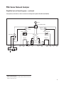
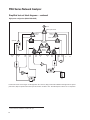
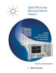
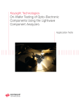
PNA Series Network Analyzer
The microwave PNA Series instruments are integrated vector
network analyzers equipped with a built-in S-parameter test set,
synthesized source, a hard disk drive, USB interfaces, and an
8.4” LCD color touch screen display. The E8362C has 3.5 mm
male 50-ohm test ports. The E8361C has 1.85 mm male 50-ohm
test ports. Included with each instrument is a mouse, keyboard
(U.S.) and a 1-year return-to-Agilent service warranty.
● E8362C
● E8363C
● E8364C
● E8361C
● N5250C
network analyzer, 10 MHz to 20 GHz
network analyzer, 10 MHz to 40 GHz
network analyzer, 10 MHz to 50 GHz
network analyzer, 10 MHz to 67 GHz1
network analyzer system, 10 MHz to 110 GHz
Test set and power configuration options
□ Configurable test set (Option 014)2
Provides six front panel access loops. Three access loops are
for port one and three for port two. The loops provide access
to the signal path between (a) the source output and the
reference receiver, (b) the source output and directional coupler
thru arm and (c) the coupled arm of the directional coupler and
the port receiver. This option provides the capability to improve
instrument sensitivity for measuring low-level signals, to
reverse the directional coupler to achieve even more dynamic
range or to add components and other peripheral instruments
for a variety of measurement applications. (see PNA Series
Microwave Data Sheet literature number 5989-7605EN for a
basic block diagram)
□ Extended power range and bias-tees (Option UNL)2
Adds two 60 dB step attenuators and two bias-tees to the
E8362/3/4C. Adds two 50 dB step attenuators and two bias-tees
to the E8361C. A step attenuator and bias-tee set is inserted
between the source and test port one and another set
between the source and test port two. (see PNA Series
Microwave Data Sheet literature number 5989-7605EN for a
basic block diagram)
□ Add receiver attenuators (Option 016)
An attenuator is added between each test port and its
corresponding receiver. Two 35 dB step attenuators are added
to the E8362/3/4C. Two 50 dB step attenuators are added to
the E8361C (see PNA Series Microwave Data Sheet literature
number 5989-7605EN for a basic block diagram).
□ High-power test set (Model E836xCH85)
This configuration combines options that are often necessary
for high power measurements (UNL*3, 014, 016, 080, 081).
The only difference between ordering Option H85 versus a
combination of the options listed above is the source
attenuator option UNL. Standard UNL includes two source
attenuators and two bias-tees. Option H85 includes the two
source attenuators, but not the bias-tees, as the bias-tees are
the power-limiting factor in the network analyzer test set. The
maximum power at the test port is +43 dBm (< 20 GHz), and
+40 dBm (> 20 GHz).
Option 080, frequency-offset mode, is included in Option H85
because it manages the phase-locking internally (instead of
depending on the R1 receiver). So if you need to use external
components in the path of the R1 receiver, it makes the
measurements simpler and more robust.
Measurement applications
□ Time-domain capability (Option 010)
For viewing reflection and transmission responses in time or
distance domain.
□ Frequency offset (Option 080)2
This option enables the PNA Series microwave network analyzers
to set the source frequency independently from where the
receivers are tuned. This ability is important for two general
classes of devices: mixers (and converters) and amplifiers.
Option 080 provides a very basic user interface.
□ Reference receiver switch (Option 081)2
Option 081 adds a solid-state internal RF transfer switch in the
R1 reference-receiver path (see PNA Series Microwave Data
Sheet literature number 5989-7605EN for a block diagram). The
switch allows the instrument to easily switch between standard
S-parameter (non-frequency-offset) measurements and frequency
offset measurements such as relative phase or absolute group
delay that require an external reference mixer. The user can set
the switch manually or remotely, but it is best used with the
frequency-converter application (Option 083), where it is controlled
automatically during the vector-mixer calibration procedure
and subsequent measurements.
□ Scalar-calibrated converter measurements (Option 082)2
With a simple setup and calibration, this application provides
the highest accuracy for conversion-loss (or gain) measurements
by combining one-port and power-meter calibrations to remove
mismatch errors. Option 080 required.
□ Vector- and scalar-calibrated converter measurements
(Option 083)2
This converter measurement adds an intuitive and easy-to-use
user interface, advanced calibration choices that provide
exceptional amplitude and phase accuracy, and control of
external signal sources for use as local oscillators. Mixer
calibration techniques include scalar-mixer calibration and
vector-mixer calibration (requires Option 081). Finally, the
frequency-converter application supports all of Agilent’s major
signal source families.
□ Embedded LO Measurements (Option 084)
This option tunes the PNA receivers to the output frequency of
the converter under test, without the need for access to internal
LOs or a common reference signal. For converters with embedded LOs, this option enables measurements of match-corrected
conversion loss/gain (requires Option 082 or 083), and absolute
group delay (requires Option 083).
1. The E8361C can be extended to 110 GHz with IF access (Option H11).
2. Up to 67 GHz.
3. UNL* does not include bias-tees. Only includes source attenuators
15