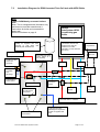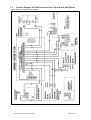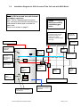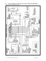
1
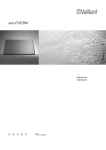
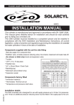
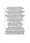
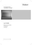
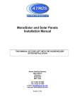
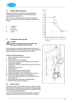
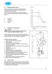
ATMOS
HEATING SYSTEMS
Twin Coil Sealed Solar System
Installation & User Manual
THIS MANUAL IS TO BE LEFT WITH THE HOUSEHOLDER
AFTER INSTALLATION
Atmos Heating Systems
West March
Daventry
Northants
NN11 4SA
Tel: 01327 871990
Fax: 01327 871905
e-mail: [email protected]
internet: www.atmos.uk.com
T2 panels (& enlarged Appendix) Issue 3.12.07
Twin Coil Sealed Solar System Ins Man
Page 2 of 15
1.0
1.1
General
Introduction
Water heated by the solar panels is pumped down to a well insulated twin coil hot
water storage cylinder under the control of an electronic controller. The solar coil in
the lower section of the cylinder provides solar heat, whilst the upper coil is
connected to the boiler to provide the back up when the solar heat is insufficient. The
solar system is sealed and requires a special glycol anti-freeze fluid to protect against
freezing. This type of system has to be designed for high temperatures and high
pressures and therefore special solar components must be used.
1.2
Selecting the location of the Solar Panel
1.3
1.2.1
Select the most southerly facing and unshaded area of the roof for the solar
panel. Be aware of the movement of shadows across the proposed location
from chimneys, trees, etc and try to minimise this effect. Often the best
position technically and visually, is in the centre of the roof.
1.2.2
The minimum angle of the roof, and therefore the solar panel, should be 30
degrees.
The maximum height of the solar panel should normally be 10 metres.
1.2.3
Ensure that there will be enough space to fit the solar panel. Because of the
flashing, in the case of roof-integrated panels, it is best to have at least one
column of tiles between the panel and a vertical edge and at least 2 rows of
tiles between the panel and the top of the roof.
Unpacking the Solar Panels and Warning
Unpack panels carefully so that they are not damaged.
WARNING
1. Take care when carrying the solar collector panels to the roof, because of their size
and weight. Weight of single panel = 44.5 Kg and size = 2090 x 1080mm.
2. Keep the panels covered while working on the roof.
When the absorber surface is exposed to light, the whole solar panel will become
very hot and the heat will be conducted to the external pipework which may become
too hot to touch.
Note that these temperatures can reach over 200 degree C and when touched
would cause severe burns.
Twin Coil Sealed Solar System Ins Man
Page 3 of 15
2.0
Installing Roof-Integrated Solar Panels
(For pantiles, etc, but not slates)
See separate leaflet available from Atmos.
3.0
Installing On-Roof Solar Panels
2 Panels
Twin Coil Sealed Solar System Ins Man
Page 4 of 15
3 Panels
Twin Coil Sealed Solar System Ins Man
Page 5 of 15
1. Remove roofing tiles in the area of solar panel assembly (upper edge of the collector panels
approx 3 to 4 rows of tiles from the ridge).
2. Fasten the supporting profile to the rafters using wood screws, 80 to 100mm above the
lathwork. Pay attention to weathering of the profile, in respect to the position of the panel.
3. Attach hooks to the supporting profile according to the picture shown. Do not tighten the
screws as further adjustment will be necessary.
4. Attach the supporting G-profile to the lower hooks, as shown in the picture. For 3 panels,
set up the G-profiles using 330mm connecting piece.
5. To the upper hooks, attach the U-profile in line with the supporting G-profile of the lower
side. For 3 panels, set up the two U-profiles using L-connector and self tapping screws.
6. Tighten all screw connections.
7. After drilling the holes for the solar panels pipework, replace the roofing tiles.
8. Position the solar panels as shown in the picture, using packing as required to space the
panels 22mm apart. Tighten the screw connections.
NOTE: The panels should be connected as shown in section 6. The compensator (for
expansion) is within the panel and has stainless steel pipe with male connector.
9. Using the self-tapping screws, secure the solar panels to the U profile. Be careful not to
strip the thread.
10. Check the seating of the parts and the tightness of all the pipe joints.
Quantity
2
3
pan
pan
2
2
2
6
8
6
8
1
1
1
1
1
1
12
16
12
16
4
6
4
8
12
16
12
16
1
1
6
8
4.0
Description
2000mm Supporting profile
1500mm Supporting profile
Bearing hook
Fastener
2215mm G-profile
1115mm G-profile
2215mm U-profile
1115mm U-profile
8 x 50mm screw
6 x 20mm screw
5.5 x 16mm A2 self tapping screw
8 x 80mm wood screw
M8 Nuts/washers
M6 Nuts/washers
330mm connecting piece C (Zn)
300mm connecting piece L (AlMgSi)
24mm diameter packing
Installing Solar Panels on Flat Roofs
Solar panels may be installed on flat roofs using a separate A-frame. Contact Atmos for more
details.
5.0
5.1
Installing the System, Operation and Maintenance
Basic Guidelines
See the System and Control diagrams
1. Compression fittings suitable for the application can be used.
2. Solar circuit pipes must be insulated with high temperature insulation (eg Armaflex).
3. The power cable must be run to the BS3 controller (via a wiring centre or junction box if
using an unvented tank) from a 230 volt, 5 amp fused, earthed electrical supply.
4. The collector and tank sensors are supplied with the BS3 controller.
5. The solar circuit must be plumbed to the tank lower coil and the tank sensor S2 (using
heat conductive paste) fitted into the sensor pocket.
Twin Coil Sealed Solar System Ins Man
Page 6 of 15
6. Ensure that the sensor cables are not in contact with uninsulated pipes, and are kept
separate from other wiring and adequately clipped. If the sensor cable is not long
enough, use a connecting box and 2 core cable (heat resistant if near any hot pipes). The
cable should not look the same as mains cable.
7. The solar expansion vessel should be pre-pressurised to 2.5 bar.
8. Fill the system with the Tyfocor LS glycol solution, without any dilution, through the filling
loop double check valve, using Solar Filling Pump set with filter(consult Atmos). Flush
through first and refill. Check very carefully for leaks.
9. Pump speed set to the highest.
10. On commissioning, bleed the manual air vents.
11. Solar system pressurised at 3 to 4 bar.
12. Solar system controller operation: System arrangement 1 selected. SMX (store max
temp) set at 60 deg C or 65 deg C (Note: A TMV valve should normally be fitted to the
hot water supply). Check that the controller is left in AUTO (ie HND1 is in auto).
13. Pump operation checked and flow rate set to 4 litres/min (based on 2 panels).
5.2
Operation of the Controller (Resol type BS/3)
Provides simple control of solar circulating pump based on adjustable temperature
differential on (DTO) and temperature differential off (DTF), measured with sensors fitted to
solar panel and hot water cylinder.
The solar pump is switched on when the difference in temperature at the solar panel sensor
S1 (indicated by channel COL at the controller) and the hot water sensor S2 (indicated by
channel TST at the controller) is larger than the given channel DTO. The solar pump is
switched off when the difference in temperature between S1 and S2 is smaller than the given
channel DTF.
If the temperature rises above the maximum storage temperature channel SMX, the solar
pump switches off. If a temperature of above 140°C (factory setting, but adjustable channel
EM at the controller) is reached at the solar panel sensor, the solar pump is switched off.
WARNING
1. The controller is electrically operated. Improper installation or attempted repair can cause
a life-threatening electric shock hazard. Only adequately qualified specialist personnel
must perform installation and commissioning. Repairs are to be carried out only by the
manufacturer.
2. Switch off the power supply to the controller before opening the housing.
3. The controller is an electronic device for use in conjunction with a hydraulic circuit in
accordance with the manufacturer's specifications. The device is not to be used for any
other purpose.
4. It may be necessary to electrically suppress strongly inductive loads in the vicinity of the
controller (contactors, solenoid-operated valves, etc.).
5.3
Inspection & Maintenance
1. Regularly check that there are no red flashing LED’s at the controller.
2. Regularly check that the system pressure at the pressure gauge at the pumping station is
approx 3 to 4 bar. Fluctuations are normal, but if the gauge shows low pressure
constantly, then contact your Installer/Service engineer. More fluid must be pumped into
the system, but only use the same type of glycol fluid as installed.
3. It is advisable to test and check the glycol fluid every 3 years, which must be carried out
by your Installer/Service engineer.
Twin Coil Sealed Solar System Ins Man
Page 7 of 15
6.0
Technical Specifications & Diagrams
Construction
Absorber
Efficiency
Other information
Outside dimensions
Weight
Frame
Absorber area
Glass
Undersidel insulation
Side insulation
Connection
All-copper absorber with highly selective
surface
Absorption
Emissivity
Working pressure
Content
2090 x 1080x 103 mm
44.5 kg
Black anodized alloy AIMgSI 0.5
2,018 m2
Solar th. = 4 mm, safety glass
Transmittance of solar radiation
e = 90%; Fe2O3 content = 0.05%
EN 572-5 Safety construction glass
Mineral wool = 66 mm thick
Mineral wool = 20 mm thick
G3 + flat packing
95 % +/- 2%
5%
2 - 4 Bar
1.1 Litre
Certification by an independent testing
laboratory ISE Freiburg
EN 12975-1,2
Maximum efficiency
Stagnation temperature
(no load operation)
η0= 0.77(77%)
202°C
Guarantee period 5 years
Life expectancy 25 – 30 years
Twin Coil Sealed Solar System Ins Man
Page 8 of 15
SOLAR SYSTEM DIAGRAM
Solar Sensor S1
(Panel sensor FKP6)
TOP OF PANELS
NOTE
FLOW should
go horizontally
into roof space,
or with a rise to
air vent before
dropping to hot
water tank.
Manual Air Vent (Fit at
highest point)
1
2
22mm solar panel FLOW
with Armaflex HT
13mm insulation
4
Solar
Panel
Solar
Panel
solar
expansion
vessel
3
1
5
2
22mm solar panel RETURN
with Armaflex HT
13mm insulation
Pump
station
and
controller
NOTE
Unvented system fittings not
shown
Expansion vessel to be fixed
240 volt
switched
supply
Top coil
Boiler connection
Sensor S3
(optional)
Bottom coil
Solar collector
Sensor S2
Drain cock at
lowest point
Hot water tank indirect
Twin Coil Sealed Solar System Ins Man
Safety
discharge
(glycol)
Atmos Heating Systems
Installation diagram for Twin coil tank with
Single station pump set & BS/3 controller
KEY
1. Integrated compensator within panel
has stainless steel pipe with male
connection (flexi connector).
2. ¾ inch brass end cap with washers.
3. 22mm ¾ inch MI compression elbow
with washers.
4. a) Connect ¾ inch brass nipple in
one end of ¾ inch brass tee.
b) Connect ¾ x ½ inch brass bush &
½ inch sensor pocket in other end.
c) Connect 22mm x ¾ inch MI
compression straight into tee branch
d) Connect assembly to panel ¾ inch nipple & washers to union
nut.
e) Insert black 6mm solar sensor
into pocket and take cable through
flashing to BS/3 controller.
5. Connect brass nuts on copper tails.
Page 9 of 15
Solar Controller BS Controls Diagram
NOTES
1. For an OSO Solarcyl unvented twin coil tank, wire the lower thermostat as shown using
a wiring centre or junction box. Fit the tank sensor S2 (using heat conductive paste)
into the sensor pocket beside the lower thermostat.
2. For a RCM/Stanley unvented twin coil tank, take the lower thermostat and remove the
control thermostat part, so that just the 85 deg C limit thermostat is left. Fit the tank
sensor (using heat conductive paste) and the limit thermostat into the lower pocket
(double segment) and bring the sensor cable out through the thermostat spare gland.
3. Keep sensor cables separate/apart from other cables.
4. An additional sensor S3 can be fitted into the pocket near the top of the tank, to provide
temperature indication only at the Solar Controller.
Twin Coil Sealed Solar System Ins Man
Page 10 of 15
7.0
7.1
Appendix
Commissioning Check Sheet
Check List
Tick/Comment
1. Solar panel is in good location and without significant shading.
2. Solar panel orientation is correct and flow pipe taken to upper
connection of panel.
3. Solar panel is securely mounted and flashing secure (if appropriate).
4. Solar panel pipes are insulated with high temperature insulation (eg
Armaflex).
5. Panel temperature sensor is fitted in place correctly.
6. Roof fixings robust and weather tight; roof penetrations made good.
7. A pressure relief valve (6 bar) fitted and discharge is taken to a safe
low level outlet.
8. Panel sensor cable (silicon type) is not in contact with the panel pipes,
and is kept separate from other wiring and adequately clipped.
9a. Power cable has 230 volts, 5 amp fused, earthed electrical supply and
cable to pump is heat resistant type.
9b. For an unvented tank, the live connection must be interrupted by the
tank lower stat (as shown in the Appendix).
10. Equipotential bonding is refitted.
11. Pump speed set to the highest.
12. Solar panel system has been filled with anti-freeze, anti-corrosion
fluid.
13. De-aeration valves manually bled.
14. Solar panel system pressurised at 3 to 4 bar.
15. Solar system controller operation checked, and the controller left in
AUTO.
16. The pump unit is fixed securely and not vibrating or noisy. Pump
operation checked and flow rate set to approx 4 litres/min for 2 panels,
alternatively approx 6 litres/min for 3 panels (based on 1litre/min per m2 of
absorber area x no of panels).
17. System operation checked and system checked for leaks.
18. Maintenance of system explained to the Customer and the Installation
Manual left with the Customer, with this sheet completed and signed.
Installed Equipment & Installer
Record
Panel type and quantity
Cylinder size & type
Controller type
Controller settings if different from
factory settings
Glycol solution type and approx litres
Installer’s Name (IN CAPITALS) or firm
Installer’s Signature
Installer’s Phone No
Date of Completion
Twin Coil Sealed Solar System Ins Man
Page 11 of 15
7.2
Installation Diagram for RCM Unvented Twin Coil tank with HE26 Boiler
Note
Tank is RCM/Stanley unvented indirect
tank
Note: This is a diagrammatic illustration only,
and does not override manufacturer’s
instructions for boiler and unvented hot
water tank.
Solar circuit shown on page 9.
Atmos
InterSystem HE26
condensing gas
boiler
Unvented tank expansion vessel
(white) as supplied with tank.
Connect to cold water inlet
assembly with braided hose.
Electrical connection; All
connections are 240 volt
therefore use 240 volt
switch live on boiler
terminals (1 is the switched
live input)
Room
thermostat
Hot water out to taps
Secondary hot water
return (blank off if
not required)
Pocket for solar
sensor S3
(optional)
Time-clock
programmer
Flow
Return
Terminal box
P&T valve
to tundish
and
discharge
Thermostat for
boiler control.
Immersion heater
Two port
motorised
valves
240 volt
switched
supply
Gas
supply
Solar cutout stat
& solar sensor
S2 pocket
Flow and return to radiators
Solar coil flow and return
connections
Twin Coil Sealed Solar System Ins Man
Cold inlet with valve
assembly and expansion
vessel as supplied with
tank
Page 12 of 15
7.3
Controls Diagram for RCM Unvented Twin Coil tank with HE26 Boiler
(Note: Diagram shows Salus controls)
Twin Coil Sealed Solar System Ins Man
Page 13 of 15
7.4
Installation Diagram for OSO Unvented Twin Coil tank with HE26 Boiler
Note
Tank is OSO unvented tank with internal
secondary expansion
Note: This is a diagrammatic illustration
only, and does not override manufacturer’s
instructions for boiler and unvented hot
water tank.
Solar circuit shown on page 9.
Atmos
InterSystem HE26
condensing gas
boiler
Electrical connection; All
connections are 240 volt
therefore use 240 volt
switch live on boiler
terminals (1 is the switched
live input)
Time-clock
programmer
Room
thermostat
Hot water out to taps
Pocket for solar
sensor S3
(optional)
Flow
Return
P&T valve
to tundish
and
discharge
Terminal box
Commissioning
valve and
Secondary hot
water return (if
required)
Thermostat for
boiler control.
Solar cutout
stat &
Immersion
heater
Two port
motorised
valves
240 volt
switched
supply
Gas
supply
Pocket for
solar
sensor S2
Flow and return to radiators
Solar coil flow and return
connections
Twin Coil Sealed Solar System Ins Man
Cold inlet with valve
assembly as supplied
with tank
Page 14 of 15
7.5
Controls Diagram for OSO Unvented Twin Coil tank with HE26 Boiler
(Note: Diagram shows Salus controls)
Twin Coil Sealed Solar System Ins Man
Page 15 of 15