1
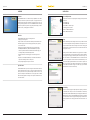
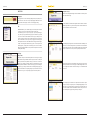
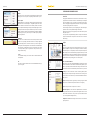
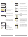
energy for a better world
User Manual
TRI-DESIGN
Version 2.0 | March 2012
Inhalt
Overview
Software
4
Functions
4
Special Feature
4
Installation
System Requirements
5
Setup
5
Uninstalling
5
First steps
Language
6
File
6
Settings
6
Help
8
User guidance and Dimensioning
Overview9
Project
9
Project Data
10
Roof Type
10
Roof Parameters
11
Modules
12
Stand
12
Graphic Dimensioning
13
Inverters
15
Shopping Cart
16
Printout
17
Export
17
Data Bases & Update
Software Update
18
Updating the module and inverter data bases
18
Terms of use
19
4_Overview
Installation_5
OVERVIEW
Installation
Software
System Requirements
The TRI-DESIGN software is a software developed by TRITEC for the dimensioning and calculation of photovoltaic systems. The program and its integrated calculation and design information provide support for project engineering and the preparation of offers. The TRI-DESIGN software allows any
photovoltaic systems to be planned easily, quickly and efficiently, in terms of
module selection, mounting systems and inverter.
In order for the software to run optimally, the following system requirements
must be met:
• Min. 800 MHz PC
• Min. 512 MB RAM
• Min. 100 MB free hard disc space
• 1024 x 768 monitor resolution
• Microsoft® Windows XP/ Vista/7
• Microsoft.NET Framework 4.0
Functions
The TRI-DESIGN software has the following functions:
• Simple project management
• European-wide location determination with deposited irradiation values
• Available language versions: German, English, French, Italian, Spanish,
Slovene and Croatian
• Planning and calculation of TRITEC photovoltaic mounting systems
TRI-STAND, TRI-STAND Aero, TRI-ROOF and TRI-VENT. They comprise
solutions for pitched and flat roofs with different installation types, for
roof integrated PV systems and building exteriors.
• Automatic calculation of mounting proposals for the designed roof
surface
• Preparation of a BOM (Bill of Materials) of all modules and installation
components including inverters for a PV system
• Clearly arranged display and export of all results
Special Feature
Setup
Start the installation by double clicking on the file Setup.exe. We recommend
to close all other applications during the installation so that system files can
be replaced without restart. After selecting the save location for the program
and program files, a Start menu folder can be selected where the link to start
the program is created.
Clicking on Continue starts the installation of the program on the computer.
You can quit the software setup at any time by clicking on Cancel. Installation
of the program and copying of the files may take some time. This step completes the installation of the TRI-DESIGN software. The last window allows
you to choose whether the software should be started immediately or at a
later time manually. Registration with the license number is required to be
able to use all features of the software to the full extent. You can obtain this
license number via www.tritec-energy.com. In this respect, you will obtain
detailed instructions in the menu item Help.
The TRI-DESIGN software presents an integrated solution which enables the
complete handling and processing of a design according to standards. Another special feature is its export functionality. It enables the user to edit,
export and directly send the BOM for all necessary components to TRITEC.
This functionality simplifies the design of solar systems and thus allows even
more efficient work.
Uninstalling
In order to remove the program completely from the computer, you will have
to uninstall it in the control panel. Click on the Start button of the task bar,
then the button Software (Windows XP) respectively Programs and Functions
(Windows Vista). Clicking on the TRI-DESIGN program and then on Uninstall
opens the wizard to remove the program. Finally, clicking on Uninstall in the
appearing window removes the program and all related files from the computer.
6_First Steps
First Steps_7
FIRST STEPS
Language
Programme Settings
The menu item Programme settings allows the addition of further parameters for the dimensioning.
The program can be used in German, English, Spanish, French, Italian, Croatian and Slovene. Click on the corresponding language abbreviation on the
top right side of the display to select the desired language setting.
File
Location: Indication of latitude and longitude in minutes instead of decimals.
Additionally, deviation of geodata search by means of which irradiation values are determined can be narrowed down.
TRI-DESIGN enables you to simultaneously plan several PV systems. The data
of each project can be stored and retrieved again at a later time.
Click on New project to set up a new project; to open already existing projects, click on Open project. When saving a project for the first time, you must
select a save location and file number under Save project. Clicking on Save
project saves the project in its current condition and replaces the existing file.
It is recommended to secure every newly set up project with Save project
directly at the desired save location. While dimensioning, the file should generally be saved at regular intervals. Entire projects can also be printed out
with design plan, company and customer data, prices as well as the bill of
materials. Optimum subdivision of the printouts is explained in the menu
item Program Settings.
Roof drawing: Depositing vertical or horizontal maintenance walkways to be
taken into account in the design. Moreover, information can be made about
the rail length of the stand to be selected. While a length of 3 m takes optimum
transport conditions into account, 6 meter long rails provide better statics.
Settings
Designer Data
Information may be entered under Designer data concerning the company
which had been charged with the dimensioning as well as the contact partner. They are shown in the printout of the project. In the case of several designers in one company, entering the editor here can show which project was
edited by whom. In addition to details of the company, you can also integrate
a company logo. Clicking on Browse under the heading Company logo, you
can select and add the corresponding image file. Upon activation of the window Take over logo, the corresponding image is shown in the printout.
Printouts: For better and clearer handling of large design projects, the printout may be distributed over several pages. It is additionally possible to enter
a roof length and/or width as of which the design is to be subdivided and
printed out.
Prices: Settings for price indications. The drop down menu offers the options
No prices, Total price only, Exact prices or VPE (packaging unit) prices. The
current price list is imported from a local data carrier via Import price list.
Price lists are available via the usual distribution channels. The option also exists of manually entering a percentage mark-up of the prices.
8_First Steps
User Guidance and Dimensioning_9
Help
User GUIDanCe anD DIMensIOnInG
Manual
The current version of the manual is provided under Help. After the desired
language version is selected, the corresponding document will be opened.
Overview
Internet Update
Regular updates are recommended so that the software will always be at the
latest status. Click on Internet Update g Programme Update for the examination of whether a new software version is available, and also for the installation of updates. Additionally, the message Internet Update appears next to
the Help menu when a new Update is available. The procedure for a software
update is described in detail in the chapter Data Bases & Update in this Manual. By using a proxy server, click on Proxy. You can make all proxy settings in
the opening window.
registration
To be able to use all software functions to the full extent, it must be activated. This is done by clicking on the button Full version on the top right-hand
side of the display. If there is no Internet connection you can also register under Help in the sub-item Registration. In the window License administration
then opening up, the right-hand side selection for activation can be clicked
on. It is also possible to postpone registration to a later point in time by selecting Continue testing.
Contact
To contact TRITEC directly, click on How to find us to obtain a PDF file with
contact partners.
Info
Select Info for a pop-up with the current version of TRI-DESIGN. Click on popup to close it again.
The program is subdivided into several main items. General data on location,
projekt and roof characteristics are first recorded under Project. Subsequent
steps follow with the selection of modules, the mounting system as well as
inverters. Shopping cart displays the bill of materials of all components which
can be subsequently printed out and exported.
General settings and functions, such as Language, Save, Print and Help are
explained in the section Programme Settings of this manual.
After the basic settings of the program, the main items must be passed
through in sequence.
It is not possible to skip individual steps, with the exception of the subitems
Project data and Inverters if only stands are to be taken into account in the
dimensioning.
Projekt
location
In Location, site data of the place are indicated where the project is to be implemented. With the exception of the field Region, all fields are mandatory
fields and if they are not completed, the software cannot plan the PV system.
When moving to the next item without filling in any information, these fields
are highlighted in red. Instead of individually completing the fields explained
below, it is possible to determine the location by means of a photo with integrated GPS data. For uploading, click on the camera symbol.
Place of irradiation/Irradiation
This function is only active if the full TRI-DESIGN version with inverter design
has been installed. Due to the indication of latitudes and longitudes, it is possible to request European-wide climate data. Clicking on the button Search
location will show the closest climatic data point. The data are 10-year means.
Country: The selection includes the countries of Germany, Austria, Switzerland, Italy, France and Spain. If a design is desired in another country, use the
selection Other location. In that case, snow and wind load data must be manually entered.
region: This field provides the opportunity of entering the region in which
the system is to be built. However, this information is not obligatory.
City: Enter the place where the system is to be realized.
latitude/longitude: In order to define the optimum distance to avoid shadowing between the module areas, latitude and longitude must be entered.
Enter the data in decimals. It is also possible to provide the data in minutes
(see section Programme Settings/Location).
Height above sea level: Enter the height in meters above sea level where the
system is planned.
10_User Guidance and Dimensioning
User Guidance and Dimensioning_11
Snow load zone/ Wind load zone: The zone can be determined using the map
data stored in the software. By clicking on the respective map, it can be
zoomed and thus allows easy reading of the values. They can be automatically taken over by another click to the respective place in the map. If the location of the system is between two wind and/or snow load zones, the higher load, thus the higher classified zone is to be applied.
Snow load value/Wind load value: If the values are known or if the location
is outside the countries offered, they can also be alternatively entered directly via the corresponding fields Snow load value and Wind load value. This replaces selecting the wind and snow load zone and the terrain category. These
values can only be entered if Unknown was selected in the drop-down menu
of the snow or wind load zone, respectively.
Terrain category: The terrain category can be set by either selecting one of
the icons or entering it manually. To obtain an explanation of the respective
category, the mouse can be moved over the respective icon. Without clicking
on the icon, the explanation appears in a separate field.
North German Plain:
If the project is located in the North German Plain, tick this box due to special
static calculations.
Project Data
The data of the respective project can here be entered. A name can be allocated to every project in the field Project name, while the other fields are
provided with the customer’s contact data.
If pitched roof as the generator surface, another menu item selection Roof
Type appears on the bottom. A mouse click is used to select between Ridged
roof, Mono-pitch roof, Hipped roof, Half-hipped roof and pavilion roof. The
completed selection must then be provided with dimensions. In fields a and
b (depending on roof type also c and d), the corresponding dimensions are
to be entered in centimetres. An exact presentation of the dimensions to be
indicated appears when the mouse is moved over the ?-icons indicated next
to the fields.
When dimensioning a flat roof project, additional data are required in addition to the roof dimensions, the roof height, orientation and slope. If chamfered is selected in the field Eaves area, another field pops up requiring the
entry of the degree of slope. If the selection is With parapet, its parapet
height must be entered.
Roof Parameters
Depending on the selection of the type of roof in the preceding menu item,
additional information is now requested with regard to the roof construction.
Upon selection of the type of roof Pitched roof, the roof construction is selected from among rafters, beams and steel beams. After selection of the roof
construction by mouse click, four fields must be completed with details on
the distances between the first and last rafter or, respectively, beam to the
roof edge, the greatest rafter/beam distance, and the number of rafters/
beams. If rafters are selected as the roof construction, the option Wooden
lathwork additionally appears under which the first and last lath are entered,
as well as distance and quantity.
Analogously, when applying a trapezoidal sheet project, information is required regarding the first and last trapezoid, as well as distance and number
of trapezoids. Additionally, in the sub-item Parameter trapezoid, additional
fields open up for sheet thickness and width of beads. If the project concerns
a design on aluminium sheet, this can also be entered here.
In case of a flat roof, the options Concrete, Rafters and Beams open up. While
no additional details are required for concrete, the procedure for rafters and
beams will be analogously to that for the pitched roof.
Roof Type
Under Roof Type, data of the characteristics of the roof are entered on which
the system will be mounted.
In a first step, the Generator surface is determined, i.e. whether the dimensioning is made on a pitched roof, flat roof or a building exterior. In this
respect, the selection Flat roof applies for all systems implemented on a horizontal foundation with a maximum slope of 5°.
With regard to the request of orientation, 0° is North, 90° East, 180° South
and 270° West. In case of a true orientation of the roof of N -5°, a value of 355
is to be entered; for an orientation of precisely South-West, the value of 225,
etc. The field Roof height requires the entry of the height from the gable to
the ground of the property while the roof slope designates the angle between the horizontal and the roof surface. By clicking on the ?-icons next to
the entries, you can view a more detailed illustration of which data will be
required. To see the graphic presentation of the individual data, it is sufficient
to move the mouse over the respective icons.
If the project concerns a building exterior, information will be required
regarding the distance which can be firmly defined. In the latter case, additional fields will open up regarding the first and last construction, as well as
distance and quantity.
12_User Guidance and Dimensioning
User Guidance and Dimensioning_13
Module
Modules are selected by means of the 4 drop-down menus
• Apply Filter
• Manufacturer
• Data bases
• Type
and according to the criteria of Nominal rating & Technology, Dimensions,
Current and Voltage.
Data Base
Various data bases can be used for the selection of modules. The TRITEC data
base exclusively includes modules from the current TRITEC product range. The
General modules data base includes nearly all modules available on the market.
It cannot be guaranteed that the data base are complete.
Aside from that, the user is able to set up its own data base – with User – with
specially selected modules. The corresponding modules must be manually entered for it. Alternatively, an individual list of modules already set up can be
created and summarized in the Favourites data base. To add a module to the
list of favourites, click on the star icon next to the drop-down menu Type.
Filter
A filter can be optionally activated for the specific search for modules. To this
end, click first on the + symbol next to the PV module filter. An additional
menu then opens in which the criteria Dimension, Nominal rating, Technology are specified according to which the selection of modules is to be narrowed down.
To set up several filters, a name must be selected for each one. Subsequently,
the individual criteria are specified. By clicking on the Add icon, the filter is
set up and thus automatically integrated into the drop-down menu Apply
Filter. To remove a filter, click on the Delete icon. Please note that the filter
will thus be deleted not only from the drop-down menu but completely.
Stand
Stand Entry
For selecting the stand, the user has the following TRITEC mounting systems
available:
• TRI-STAND for flat roofs and pitched roofs, as well as building exteriors
• TRI-STAND Aero for flat roofs
• TRI-VENT for trapezoidal sheet roofs
• TRI-ROOF for roof-integrated solutions
Detailed information regarding the respective mounting as well as information on technical properties are listed in the mounting instructions.
Depending on the data entered in the preceding steps, the software automatically selects the suitable stand. The menu item Stand Entry presents all
options which result within a system and accordingly are not equally active
with all stands.
The following options are possible for the TRI-STAND mount:
• Pitched roof: Insertion or clip system
• Flat roof: Type of support and shadowing angle
• Building exterior: Connection or no connection, respectively
TRI-STAND and TRI-ROOF can be selected in the design Aluminium bright or
Aluminium black.
Fastening
In the section Fastening, the components of the mounting system are specified
as far as the mounting system TRI-STAND was selected for the dimensioning.
Optionally, roof hooks from a customized product range can be used. Click
on the roof hook symbol with the question mark and enter the maximum admissible load for the fastening. For the selection of this item and the use of
third-party fastening means, it is absolutely necessary to take into account
the TRI-STAND warranty conditions and to consult the internal sales service!
If Roof hooks were selected as fastenings, the connection of hooks and rails
is selected in a last step.
Graphic Dimensioning
Adding Restricted Areas
You can create any number of restricted areas on the roof. They can be either
real obstacles, such as chimneys, dormers or aerials, or areas where no module should be installed, for example, in order to keep maintenance walkways
clear.
The creation of a restricted area always begins with clicking on Restricted
area. In the now appearing window, enter the dimensions. Detailed information on the individual data can be displayed by clicking on the adjacent
?-icon. You place the restricted area by either using the entry of options Start
X and Start Y or later via the drag and drop feature. If you enter, for example, for Start X the value 150 cm and for Start Y the value 370 cm, the software
will create a restricted area beginning 1.5 m from the left and 3.7 m from the
lower edge of the roof. This is the point of the lower left corner of the restricted area which continues with the stated dimensions.
To keep track of things with several restricted areas of a roof, we recommend
entering a name for each restricted area in the field Name. With the same
process, any number of restricted areas can be added.
To subsequently edit or delete a restricted area, select it by double clicking
on it. Now you can move it across the roof by simple drag and drop or edit it
by a right click on it. Since several objects can be selected at the same time,
the option to edit always applies to all selected restricted areas.
14_User Guidance and Dimensioning
User Guidance and Dimensioning_15
Module field
Clicking on Module fields opens a window with all parameters required to
cover the roof with solar modules. For covering a prior defined field, it is entered with the selection of the first check boxes Number of columns and Number of rows. Alternatively, a Number of PV modules or the desired Output
may be entered.
The next section determines how the modules are to be placed on the roof.
To do this, enter Start X and Start Y where the edge of the module field is entered in X and Y direction, or select a corner of the roof to which the modules
are aligned. The option of a symmetrical covering of the roof is also possible.
In the bottom section of the window, the modules are positioned in Portrait
or Landscape format. In addition, a minimum distance of the module field to
the roof edges can be entered. Depending on the module use, various applications may be impossible and their corresponding fields inactive.
This way, you can create as many individual module fields until the roof is
covered completely.
Buttons for editing the module area
Depending on the selected module and entered project data, buttons can be
used on the left edge of the screen to edit the module area. Buttons comprising options that are not available can only be seen in outlines. All buttons
have mouseovers describing their respective function. Inactive buttons are
shaded grey. The buttons are faded in after selecting a module by doubleclicking it.
Other Options of Graphic Dimensioning
In addition to the above described basic features of the graphic design, additional options can be called up by right-clicking on the respective modules,
restricted areas or roof areas.
By right-clicking on the empty roof area, the following options appear:
• PV modules: Select or remove all modules or, respectively, add additional
modules in portrait or landscape format.
• Zoom: Picture detail is enlarged, reduced or automatically properly adjusted
• View: Switch between Levels, between Stand-system view and Module view.
Additionally, Load zones, Coordinates and Grid can be shown or hidden.
When right-clicking on a restricted area, the following functions appear:
Select restricted area, Features, or Show or Hide coordinates. Furthermore,
the origin of the graphic design can be set at a restricted area by clicking on
Coordinates g Set origin.
Right clicking on one of the modules can select the module or show the Module
grid. The module grid shows the complete design of the field with modules
without restricted areas. Additionally, by right-clicking on a module – as with
the restricted areas – it is possible to Show coordinates or Hide coordinates
and set the Origin at the respective module.
Adding a new module above or below the selected module.
Shifting modules to the left, respectively right.
Shifting modules to the top and, respectively bottom. Select the desired modules by double-clicking on a single one or, in case of several modules, by drawing a frame around the modules. Now, they can be moved in the desired
direction.
Cover still free roof area symmetrically with modules in portrait format. Cover
still free roof area symmetrically with modules in landscape format.
Zoom in the picture of graphic design, respectively zoom out the picture detail.
Zoom out the picture of graphic design, respectively zoom in the picture detail.
Inverters
Selection
Inverters for the system to be designed are selected according to a similar
principle as the determination of the modules before.
Data Base
Various data bases are available for the selection of inverters. The TRITEC data
base exclusively includes models from the current TRITEC product range.
Aside from that, the user is able to set up its own data base – with User – with
specially selected inverter models. The corresponding inverters must be manually entered for it.
Alternatively, an individual list of inverters already set up can be created and
summarized in the Favourites data base. To add a module to the list of favourites, click on the star icon next to the drop-down menu Selection.
16_User Guidance and Dimensioning
User Guidance and Dimensioning_17
Filter
A filter is optionally available for the specific search for inverters. To this end,
click first on the + symbol next to the Inverter filter. An additional menu then
opens in which the criteria are specified according to which the selection of
inverters is to be narrowed down.
To set up several filters, a name must be selected for each one. Subsequently,
the individual criteria are specified. By clicking on the Add icon, the filter is
set up and thus automatically integrated into the drop-down menu Stored
filters for Inverter selection. To remove a filter, click on the Delete icon. Please
note that the filter will thus be deleted not only from the drop-down menu
but completely.
Printout
Selection printouts activates or, respectively, deactivates all desired printouts.
The selection can now be printed by clicking on Print. By clicking on Print preview, a preview of the selected items can be displayed.
These functions are also found in the menu File.
For better clarity, a specific printing area of the design can be specified. This
function is found in the menu Programme settings under Printouts.
After you have adjusted still further data in the sub-item Design parameters,
click on Calculate design.
Result
The result of inverters is now displayed in a table. Values regarding performance ratio and yield can be gathered from it. Then click on Apply to conclude the dimensioning.
Shopping Cart
Current Bill of Materials
The shopping cart will first issue a bill of materials of all modules, inverters
and mounting parts for the project. By clicking on the corresponding
column designation, the enumeration of items can also be sorted according
to article number, quantity, (packaging) unit and order quantity.
Manual Bill of Materials
The bill of materials can now be changed at random by adding components
or deleting them from the list.
To expand the list, either use the search function or, for preselection, the adjacent drop-down menu Group of articles. Selection is made by clicking on
the corresponding article so that it is highlighted in blue. After determination of the quantity, taking over into the existing bill of materials will follow
by clicking on Apply.
It is also possible in the current bill of materials to change (Edit) or delete (Remove) the quantity of articles. Both entries can be cancelled again by clicking
on Resetting.
Export
The completed bill of materials can be exported in CSV format. The lower half
of the window includes the category Export bill of materials. By simply clicking on Export, the window opens to enter the location for the file to be saved
to. Having selected the save location and naming the file, it can be exported
and saved by clicking on Save.
Terms of use_19
18_Data bases & Update
Data bases & Update
TERMS OF USE
Software Update
Please read the terms of this licence agreement carefully before using the product. The product
contains software that TRITEC makes available to use exclusively to you as a customer. The
following agreement is a legally binding agreement between you, the user, and TRITEC, the
publisher. By installing the software you agree to the following terms of use. If you do not
agree to the terms of this agreement, please do not use the software and remove it from
your computer.
Click on Help Ò Internet Update to check for new software versions and install updates. The now opening window shows the currently installed software version and the latest available update version. To check for available
updates and install any available ones, the computer must be connected to
the Internet. If the message “Your version is up to date” appears, no new versions of the software and thus no updates are available.
If the installed and the latest available version are not identical, you will see
the message “Your version is obsolete”. In order to continue working comfortably with the TRI-DESIGN software, you should now update the software.
To start this process click on OK. Depending on your Internet connection,
downloading the required files may take some time. When the download of
all data has been successfully completed, the installation of the update must
be confirmed in the appearing window. The Installation Wizard will guide
you through the update installation, which is identical to the first installation
of the programme (see above).The programme section Software Update offers two additional options.
Clicking on Force programme download downloads the latest software
version from the server, independent of the current version. This option may
become necessary if an error occurred during the last download and the update could not be installed correctly.
When using a proxy server, click on Proxy. You can make all proxy settings in
the opening window.
You can at any time cancel the update and return to the normal software
screen by clicking on Close.
Updating the module and inverter data bases
The programme’s module and inverter data base are automatically updated
each time the software is updated. By regularly updating the software therefore, not only the programme, but also the content of the data bases is kept
up to date. This way new modules and inverters can be loaded and used in
the TRI-DESIGN software quickly and easily. The process of updating the software is described in the previous chapter.
1. Copies and distribution
The TRI-DESIGN software was developed for TRITEC and is protected by copyright. Copying
the programme is only allowed for data backup purposes. Copies of the programme documentation are prohibited. Transferring, renting, leasing or otherwise making the programme
or the programme documentation available to third parties is not allowed without the previous written consent of TRITEC.
2. Reservation of intellectual property rights
Notwithstanding any changes or adjustments made by you or for you, the programme, the
programme documentation and any parts thereof, all copyrights, patents and other intellectual rights contained therein shall remain the absolute property of TRITEC. By installing
the software you confirm that you do not have any other rights in the programme or its programme documentation than the rights explicitly granted in this agreement.
3. Data bases
The solar module and inverter data bases used in this software have been checked with the
greatest possible care and are updated and adjusted if necessary. However, discrepancies and
mistakes cannot be excluded. Therefore, no guarantee as to the correctness and completeness of the used data is given.
4. Guarantee
The publisher does not guarantee that the software is free from defects, runs without disruption, meets the expectations of the user and is suitable for certain user purposes or does
not breach the rights of third parties. The programme is designed to assist in the design and
does not replace detailed planning. The identified system configuration is only one possible
model, the calculation results represent only a projection. Subject to technical changes and
errors.
5. Limitation of liability
TRITEC is not liable for any direct or indirect losses or consequential losses, including, but not
limited to, loss of profit, not realised cost savings, incorrect calculations, loss of data or
increased costs of the user or any other financial losses, the granting of rights of use, the use,
the malfunction of the software or disruptions while running the software. The above limitation of liability applies also if the publisher has been informed of the possible occurrence
of any such loss. TRITEC is only liable for losses and damages, if the company is guilty of
intention and gross negligence. This limitation of liability applies to all damages claims,
irrespective of their legal basis, including, but not limited to, contractual, pre-contractual
contract-similar claims and claims arising from torts. This limitation of liability also applies to
all executive and non-executive employees of TRITEC and all representatives and agents of
TRITEC engaged in the development, marketing or delivery of the software. It is the sole responsibility of the user to ensure that he himself and his employees have the required knowledge to install and use the software correctly. TRITEC is not liable for problems and damages arising from the insufficient knowledge of the software users.
TRITEC, March 2012
© All rights reserved.
www.tritec-energy.com