1
1
WFL 2060UC & WFR 2460UC
Washer Training Program
LED display model - WFL2060UC
Digital display model - WFR2460UC
1st Edition/Revision 5 (1/20/04)
2
WFL 2060 & WFR 2460 Training Program
•
•
•
•
•
•
•
•
•
Features and Benefits
Product Description
Warranty
Installation
Operation
Disassembly
Reassembly
Wiring Diagram
Service Tips
1st Edition/Revision 5 (1/20/04)
3
Features and Benefits
• Larger door - 25% larger vs. WFK 2401
• Larger opening - 15% larger vs. WFK 2401 (easier
•
loading and unloading)
Larger drum - 19% larger vs. WFK 2401 (13 lb. capacity
vs. 11 lb. for WFK 2401)
•
•
•
•
•
•
•
•
•
Very energy efficient - Energy Star rated
Stainless steel drum - won’t rust & is gentle to clothes
Uses little water
3-Tier water fill for fast & equal water fill
180° door opening
Up to 5 rinses
Suds sensing - rinses out suds leaving no soap film
Unbalanced load sensor - adjusts spin to balance load
UL listed (U.S. & Canada)
1st Edition/Revision 5 (1/20/04)
4
Extra Features and Benefits -- WFR 2460
•
•
•
•
•
•
•
•
Continuous cycle notification - digital display
Sensotronic II Plus electronic control
Accurate water level control independent of water pressure
Digital clock
Real time cycle finish (displays actual time of day cycle stops)
Real time delay (enter actual time of day for wash to end)
Reduced ironing
Interactive language display - choose desired language
(English, French, Spanish, German)
• Continuous suds sensing
• Child lockout
1st Edition/Revision 5 (1/20/04)
5
Product Description
• Electronic Sensotronic controls
• UL listed (U.S. & Canada)
• Larger capacity & door opening
• Drain hose & cord holders
• Detergent & softener dispenser
Adjustable
spin speeds
• Regular/Cotton, Permanent Press,
Delicates & Hand Washables settings
• 180º door opening
Electronic
controls
Energy
Star rated
• Stainless steel inner drum
• Durable Polinox outer drum
• Power Wash, Rinse Plus & Quick
Wash buttons
• Adjustable spin speeds
• Guaranteed temperatures
Safety
door lock
Accessible drain trap
1st Edition/Revision 5 (1/20/04)
6
Warranty (1)
Bosch Washers and Dryers Limited Lifetime Warranty
Statement of Limited Warranty
The warranties provided by BSH Home Appliances ("Bosch") in this Statement of
Warranties apply only to Bosch clothes washers and dryers sold to the first using
purchaser by Bosch or its authorized dealers, retailers or service centers in the United
States or Canada. The Warranties provided herein are not transferable, and take place
from date of installation.
1 Year Full Limited Warranty
Bosch will repair or replace, free of charge, any component part that proves defective
under conditions of normal home use, labor and shipping costs included. Warranty
repair service must be performed by an authorized Bosch Service Center.
2 Year Limited Warranty
Bosch will provide replacement parts, free of charge, for any component part that proves
defective under conditions of normal home use, shipping costs included.
1st Edition/Revision 5 (1/20/04)
7
Warranty (2)
5 Year Limited Warranty On Electronics
Bosch will repair or replace, free of charge, any microprocessor or printed circuit
board that proves defective under conditions of normal home use for a period of
five years from the date of original installation, labor charges excluded.
5 Year Limited Warranty On Motor
Bosch will repair or replace, free of charge, any pump or component part of the
pump that proves defective under conditions of normal home use for a period of
five years from the date of original installation, labor charges excluded.
5 Year Limited Warranty On Cabinet Rust-Through
Bosch will replace any cabinet part, free of charge, if that cabinet part should rust
through under conditions of normal home use, labor charges excluded.
Lifetime Limited Warranty Against Stainless Steel Rust-Through
Bosch will replace your clothes washer or dryer, free of charge, with the same
model or a current model that is equivalent or better in functionality if the drum
should rust through under conditions of normal home use, labor charges excluded.
For location of nearest repair depot call 1-800-944-2904 from 5:00 AM - 5:00 PM
M-F (Pacific time)
1st Edition/Revision 5 (1/20/04)
8
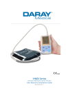
Warranty -- Serial # Label
The serial # label, located on the rear of the washer, shows
necessary warranty information.
6
Serial #
label
6
• Model # - “WFR2460UC/01”.
•
Serial # - “FD 8108”. To find when the product type
was built, add 20 to the 1st two digits to get the year
(81 + 20 = 101 Æ product type was built in 2001).
The last two digits show the month (08 = August).
Factory serial # - Can convert
factory serial # to FD # for
warranty use. 1st 2 digits show
factory # (45 = Berlin), 3rd digit
shows year (1 = 2001), 4th & 5th
digits show month built (08 =
August). So, serial # starting with
“45108…000320” = washer built
@ Berlin with FD 8108 700032.
1st Edition/Revision 5 (1/20/04)
9
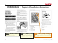
Installation -- Reprint of Installation Instructions
(“utility knife”)
Flat (blade) screwdriver.
Be sure to follow all
national & local codes.
NOTE:
“Mains” is the
European term for “power”,
so “mains cable” = “power
cord”.
HINT:
HINT: Cold & hot water connections
are clearly marked on the rear of the
washers.
1st Edition/Revision 5 (1/20/04)
10
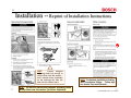
Installation -- Reprint of Installation Instructions
;
L
L
HINT: To avoid damaging washer, don’t move it
while the feet (leveling legs) are extended.
1st Edition/Revision 5 (1/20/04)
11
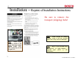
Installation -- Reprint of Installation Instructions
,
Loosen transport
(shipping) bolts just enough to
remove them from the washer -don’t unscrew them completely
so the bushings fall from the
bolts into the washer frame.
HINT:
HINT: Be sure to remove the transport (shipping) bolts
& keep them near the washer (for future shipment).
HINT: To eliminate possibility of leaking,
don’t overtighten fittings.
Teflon tape
can also be used on all threads.
1st Edition/Revision 5 (1/20/04)
12
Installation -- Reprint of Installation Instructions
HINT: The washer uses a
NEMA 6-15P 240V, 15A, 3wire plug, which mates to a
NEMA
6-15R
outlet
(receptacle).
HINT: Bosch dryers include a NEMA 6-15R outlet which the
washer NEMA 6-15P 240V, 15A, 3-wire plug can be plugged into.
HINT: “Mains” is the European term for
“power”, so “mains cable” = “power cord”.
1st Edition/Revision 5 (1/20/04)
13
Installation -- Reprint of Installation Instructions
Be sure to remove the
transport (shipping) bolts!
HINT:
When moving an existing
washer, screw in the feet (leveling
legs) first so they won’t be damaged.
HINT:
Bosch dryers
include a NEMA 6-15R
outlet which the washer
NEMA 6-15P 240V,
15A, 3-wire plug can be
plugged into.
HINT: “Earth” is the European term
for “ground”, so “earth leakage” =
“ground fault” (GFCI or GFI
receptacle).
1st Edition/Revision 5 (1/20/04)
14
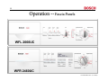
Operation -- Fascia Panels
WFL 2060UC
WFR 2460UC
1st Edition/Revision 5 (1/20/04)
15
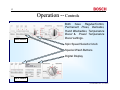
Operation -- Controls
WFL 2060UC
Both have Regular/Cotton,
Permanent Press, Delicates,
Hand Washables, Temperature
Boost & Power Temperature
Boost settings.
Spin Speed Selector knob
Special Wash Buttons
Digital Display
WFR 2460UC
1st Edition/Revision 5 (1/20/04)
16
Operation -- Sensors (1)
1A. Load Sensor (WFL2060UC)
At a predefined points during the initial fill, the washer determines if it needs more water using a pressure switch. This is
due to differences in the absorption of the laundry and the size of the loads.
1B. Dynamic Load Sensor (WFR2460UC)
During the entire fill the washer continually adjusts for the size of the load and determines if more water is needed using an
analog pressure switch and a flow meter.
2. Digital Temperature Sensor (WFL2060UC & WFR2460UC)
The thermostat monitors the temperature of the water and controls the length of time the heating element is on, ensuring
the proper temperature for the chosen cycle.
3A. Suds Sensor (WFL2060UC)
During the beginning of the1st rinse/spin phase, the washer determines if there are excessive suds and automatically adds
2 rinses (if necessary). This is accomplished via the pressure switch and the motor synchronization system.
3B. Continuous Suds Sensor (WFR2460UC)
Checking the pumping out phase of the main wash, the beginning of the 1st rinse/spin phase and the actual spin speed vs.
the programmed spin speed, the washer determines if there are excessive suds and automatically adds up to 2 rinses (if
necessary). This is accomplished via the pressure switch, analog pressure switch and the motor synchronization system.
4. Unbalanced Load Sensor (WFL2060UC & WFR2460UC)
During the final spin cycle the washer monitors the positioning and balance of the load. If the load unbalanced, the washer
stops and adjusts the load up to 15 times and reduces the spin speed to finish the cycle. This is accomplished via the
motor synchronization system.
1st Edition/Revision 5 (1/20/04)
17
Operation -- Sensors (2)
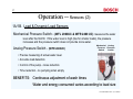
1A/1B. Load & Dynamic Load Sensors
Mechanical Pressure Switch - (WFL 2060UC & WFR 2460 UC) measures the water
level after the first fill. If the water level is high (like for smaller loads), the pressure
increases and the pressure switch does not provide more water.
Analog Pressure Switch - (WFR 2460UC)
Mechanical Analog
Pressure Pressure
Switch
Switch
• Precise measuring of actual water level
• Accurate load detection
• Control of the pump - noise reduction
• Time reduction - no pumping when empty
BENEFITS: Continuous adjustment of wash times
Water and energy consumed varies according to load size
1st Edition/Revision 5 (1/20/04)
18
Operation -- Sensors (3)
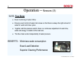
1A/1B. Flow Meter
¾ Exact monitoring of water inflow.
¾ Ensures exact control of water inlet valves so that there is always the right amount of
water for wash and rinse cycles.
¾ Together with the pressure switch, there is a continuous adjustment of wash time,
water and energy in relation to the load size.
¾ The flow meter works independently of water pressure.
BENEFITS: Minimizes water consumption
Exact Load Detection
Superior Cleaning Performance
1st Edition/Revision 5 (1/20/04)
19
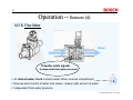
Operation -- Sensors (4)
1A/1B. Flow Meter
Water
Propeller emits signals
(independent from water pressure)
9 An internal water clock monitors water inflow via soak compartment.
9 Ensures exact control of water inlet valves - always right amount of water.
9 Independent from water pressure.
1st Edition/Revision 5 (1/20/04)
20
Operation -- Sensors (5)
2. Digital Temperature Sensor
Both models are equipped with the
Temperature
Sensor
to
deliver
guaranteed wash temperatures
Thermostat & Heating
Element
1st Edition/Revision 5 (1/20/04)
21
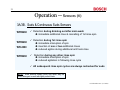
Operation -- Sensors (6)
3A/3B. Suds & Continuous Suds Sensors
WFR2460
WFR2460
WFL2060
WFR2460
9 Detection during draining out after main wash
Î immediate additional rinse & cancelling of 1st rinse spin
9 Detection during 1st rinse spin
Î immediate interuption of spin
Î insertion of one or two additional rinses
Î reduced agition during additional anti foam rinse
9 Detection during any other rinse spin
Î immediate interuption of spin
Î reduced agitiation in following rinse cycle
9 All subsequent rinse spin cycles are always rechecked for suds
NOTE: Suds build-up usually occur only when way too
much detergent is used with lightly soiled loads.
1st Edition/Revision 5 (1/20/04)
22
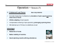
Operation -- Sensors (7)
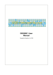
4. Unbalanced Load Sensor
New 2-step detection
9 Accurate measuring of unbalance by deviation of spin speed and slow
down time of drum
9 Infinite adapting of spin speeds
9 Compensates reducing of spin speeds by prolonging spinning times
9 Will attempt up to 15 times to redistribute a load
Advantages:
9 Reduction of noise
9 Better stability of machine
9 Good spinning results with big unbalances
1st Edition/Revision 5 (1/20/04)
23
Operation -- Sensors (8)
4. Unbalanced Load Sensor
New 2-step detection
I
II
III
Spin speed [rpm]
1200
1000
800
600
400
200
max. 15 trials
IV
0
load distribution
good
uneven
bad
none
unbalance
small
medium
big
dangerous
Spin speed (rpm)
1200 (max.)
1000 (reduced)
800 (low)
no spinning
spinning profile
I
II
III
IV
After 4 attempts
After 7 attempts
After 14 attempts
1st Edition/Revision 5 (1/20/04)
24
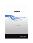
Operation -- Cleaning Drain Pump Trap
Larger objects such as coins and paper clips are collected in the drain pump trap
so they won’t plug up or damage other parts of the washer. The drain pump trap
can easily be cleaned by customers.
2
5
7
3
6
4
1
1st Edition/Revision 5 (1/20/04)
25
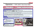
Operation -- WFR 2460UC Sales Demo Mode
CAUTION:
To avoid danger of electrical
shock, make sure the washer is unplugged
before changing any electrical connections!
IMPORTANT:
When reselling any WFL2060 or WFR2460 washers from display
floors, replace the white (or gray) drain pump connector so washers will run properly
and replace the shipping bolts so washers won’t be damaged during shipment.
SALES DEMO MODE PROCEDURE: Preparing WFR2460 washers for display involves removing three shipping bolts and
disconnecting the drain pump. To set up WFR2460 washers for display:
Conversion: Make sure the washer is unplugged and is not connected to any water lines.
1. Remove the three shipping bolts from the washer back panel, removing the top bolt last. Each bolt has an insert wedging up to
the inside of the back panel. When removing bolts, loosen them, then move them (up, left or right) until they slide out the large
circular holes (matching the insert sizes). Don’t unscrew shipping bolts completely so inserts won’t drop into the washer base.
After removing bolts, cover the holes with white caps included with the washer.
2. To access the white (or gray) drain pump connector from the back of the washer, remove the back panel by removing (7) T-20 & (4)
T-30 Torx screws. Pull the white (or gray) drain pump connector to remove it, then secure the loose connector away from the
frame or any washer parts with electrical tape (to avoid possibility of electrical shock).
3. Replace the back panel, then attach the fuscia label to the rear of the washer so its visible.
Power hook-up: Plug the washer into a 120V/240V transformer, then plug the transformer into a 120V, 15A power outlet.
Using demo mode: Rotate the cycle selector knob to the “Spin” position and then push the “Start” button to perform a complete
spin cycle. To interrupt the spin cycle, push the “Start/Pause” button.
HINT: Before starting, make sure you have
the following:
9 B 120V/240V transformer
9 Fuscia demo mode label (“IMPORTANT”)
9 Access to 120V, 15A, 60Hz electrical outlet
9 T-20 & T-30 Torx screwdrivers
9 Electrical tape
NOTE: Do not connect WFL2060 washers
for sales demonstration -- all lights will turn
on and washers won’t run.
WFR2460 drain pump is
located at washer right
front
corner
(photo
viewing rear of washer)
IMPORTANT
Shipping bolt locations
Suggested placement for fuscia label
(“IMPORTANT”)
Pull off white (or
gray) drain pump
electrical connector
1st Edition/Revision 5 (1/20/04)
26
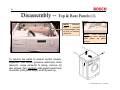
Disassembly -- Top & Rear Panels (1)
NOTE:
Washers
have 2 concrete
counterweights (top
& front) to dampen
vibrations.
NOTE:
When removing
top panel, don’t damage
white plastic top panel
latches.
To remove top panel to access control module,
dispenser, inlet valves, pressure switch(es), drain
reservoir, surge protector & wiring, remove (2)
rear screws, then carefully slide panel toward rear
of washer (until panel stops) and lift panel up.
1st Edition/Revision 5 (1/20/04)
27
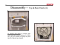
Disassembly -- Top & Rear Panels (2)
To remove rear panel to access drive
motor and rear of drum, remove (7) T-20 &
(4) T-30 Torx screws and gently lift panel
up (off of tabs at top of panel).
1st Edition/Revision 5 (1/20/04)
28
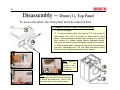
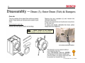
Disassembly -- Drum (1), Top Panel
To access the drum, the front panel must be removed first.
1
TO REMOVE FRONT PANEL (to access drum):
• c Remove top panel.
• d To remove fascia panel, first remove T-10 Torx screw on
right endcap and T-20 Torx screws on either side of fascia
panel. Remove dispenser drawer (after pushing blue tab) and
then remove (3) screws located behind dispenser drawer.
Gently pull the bottom of the fascia panel away from the washer.
2
• e Remove base panel (“toe kick”) by opening & removing drain
trap door, unscrewing one T-20 Torx screw and gently pulling
the bottom of the base panel away from the washer.
2
2
2
HINT: Dispenser
screws
are
recessed -- use a
screwdriver, not
a socket set.
HINT: When accessing door seal, door
seal spring or door latch, it’s not necessary
to remove the fascia panel. Remove only
the bottom right corner dispenser screw.
12
3
1st Edition/Revision 5 (1/20/04)
29
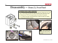
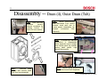
Disassembly -- Drum (2), Front Panel
TO REMOVE FRONT PANEL (continued):
• f Carefully loosen door seal clamping rings (outer/inner), taking care not to tear
seal. Loosen clamp and disconnect water fill tube from seal, then remove seal.
4
4
• g Remove two T-20 Torx front panel screws from bottom of front panel.
• h To remove front panel, carefully pull bottom of panel out away from washer.
• i Disconnect door latch connector.
4
6
5
4
5
7
HINT: When removing door
seal, loosen clamp to water fill
tube and disconnect tube from
door seal.
1st Edition/Revision 5 (1/20/04)
30
Disassembly -- Drum (3), Outer Drum (Tub) & Dampers
HINT:
“Jacket” weight is the concrete
counterweight on the top of the outer drum.
13.2 x 300 mm drill bit # 340700
1st Edition/Revision 5 (1/20/04)
31
Disassembly -- Drum (4), Outer Drum (Tub)
HINT: After removing
crossbar
screws,
remove crossbars by
rotating bottom of
them out from washer.
HINT: Before disconnecting
wire harnesses from control
module, mark each one to
insure proper reassembly (as
several
connectors
look
identical).
HINT: To access wire harness
connectors to disassemble
them, separate control module
from fascia panel by carefully
prying back plastic clips
around the module.
HINT:
Unscrew band
screws and remove band
from front counterweight.
HINT: Loosen spring clamps and
disconnect hoses from dispenser.
1st Edition/Revision 5 (1/20/04)
32
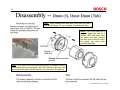
Disassembly -- Drum (5), Outer Drum (Tub)
HINT: When installing outer drum bolts, screw them in by hand
onto the first thread. Do not overtighten or cross-thread them.
NOTE: WFL 2060 drums use a
separate gasket with bolts kit #
265964. WFR 2460 drums have
the gasket and bolts included
with front drum # 238410 (where
the gasket and bolts aren’t
provided separately).
HINT: WFL 2060 & WFR 2460 outer drums (“tubs”) are made by different
vendors and can’t be interchanged. Both WFR 2460 front and rear outer
drums should be replaced at the same time (if one needs to be replaced).
1st Edition/Revision 5 (1/20/04)
33
Disassembly -- Drum (6), Rear Bearing
HINT: When installing rear bearings
for WFR 2460 models, replace the
front outer drum with gasket and
bolts as well. When installing outer
drum bolts, screw them in by hand
onto the first thread.
Do not
overtighten or cross-thread them.
1st Edition/Revision 5 (1/20/04)
34
Disassembly -- Drum Drive Motor
1st Edition/Revision 5 (1/20/04)
35
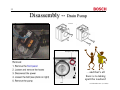
Disassembly -- Drain Pump
…and that’s all
there is to taking
apart the washers!
1st Edition/Revision 5 (1/20/04)
36
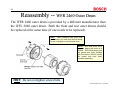
Reassembly -- WFR 2460 Outer Drum
The WFR 2460 outer drum is provided by a different manufacturer than
the WFL 2060 outer drum. Both the front and rear outer drums should
be replaced at the same time (if one needs to be replaced).
When installing outer drum bolts,
screw them in by hand onto the first thread.
Do not overtighten or cross-thread them.
HINT:
NOTE: WFL 2060 drums use a
separate gasket with bolts kit #
265964. WFR 2460 drums have
the gasket and bolts included
with front drum # 238410 (where
the gasket and bolts aren’t
provided separately).
HINT: Do not overtighten screws/bolts.
1st Edition/Revision 5 (1/20/04)
37
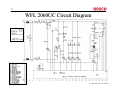
WFL 2060UC Circuit Diagram
1st Edition/Revision 5 (1/20/04)
38
WFL 2060UC Wiring Diagram
HINT: “Mains” is the
European term for
“power”, so “mains
suppressor” = “power
(surge) suppressor”.
1st Edition/Revision 5 (1/20/04)
39
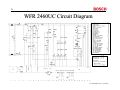
WFR 2460UC Circuit Diagram
1st Edition/Revision 5 (1/20/04)
40
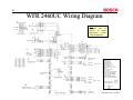
WFR 2460UC Wiring Diagram
HINT: “Mains” is the
European term for
“power”, so “mains
suppressor” = “power
(surge) suppressor”.
1st Edition/Revision 5 (1/20/04)
41
WFL 2060 & WFR 2460 Service Tips -- Ratings
•
Rated 240VAC, 15A, 60 Hz (uses 11A max.).
•
Hot & cold water inputs, 3/4” NPT
•
Two concrete vibration dampeners, top & front
•
Uses NEMA 6-15P 240V, 15A, 3-wire plug
•
Spin speeds 600-1000 RPM (WFL 2060) or
600-1200 RPM (WFR 2460)
•
Uses Polinox outer drum - quieter & dent
resistant compared to ss
•
UL listed (U.S. & Canada)
1st Edition/Revision 5 (1/20/04)
42
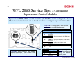
WFL 2060 Service Tips -- Configuring
Replacement Control Modules
Replacement WFL 2060 control modules (# 481304) aren’t configured. Please
follow these instructions to set on-board switches to configure replacement modules.
CAUTION: If settings aren’t done correctly,
washers can eventually be damaged!
Switch S1
Switch # Setting
off
1
on
2
on
3
off
4
on
5
off
6
off
7
on
8
Notes
Sets spin speed to 1000 RPM max.
Sets panel buttons to Power Wash ,
Rinse Plus & Quick Wash and
enables spin selector knob.
Sets hot water inlet on.
U.S. model variations enabled.
Switch S10
CAUTION: Static electricity can damage
module components. Take care to shield
modules from static electricity.
Switch # Setting
on
1
off
2
Notes
HINT:
Modules
cannot be configured
using the washer
control panel.
1st Edition/Revision 5 (1/20/04)
43
WFR 2460 Service Tips -- Configuring
Replacement Control Modules
Replacement WFR 2460 control modules
(# 484014) aren’t configured.
Please
follow these instructions to configure
replacement modules.
•
After installing module, enter test program by first
pushing and holding Menu & Select buttons, then
rotating selector switch (dial) ccw to Permanent
Press Cold (until display comes on).
•
Push Menu button repeatedly to scroll to test “T5”:
Model Variant Coding. Red light on Start/Pause
button will be flashing. Push Start/Pause button to
enter test T5 to change #’s (red light will stop
flashing when test T5 has been entered).
•
Push Menu button to scroll to each # (when desired
# is flashing). For each #, push Select button until
correct setting is chosen, then push Start/Pause
button to save setting. Repeat until settings for all
eight #’s are saved -- U.S. washers must show
42010011.
Sample Displays
42010011 T5: Variant
Push Menu button to select 1st #
for max. spin speed (until 1st #
flashes), then push Select button
until “4” (for 1200 RPM max.) is
chosen. Push Start/Pause button
to save setting.
42010011 T5: Variant
Push Menu button to select 2nd #
for water inlet (until 2nd #
flashes), then push Select button
until “2” (hot water) is chosen.
Push Start/Pause button to save
setting.
42010011 T5: Variant
When settings for all eight #’s are saved, exit test
program by rotating selector switch (dial) cw to Off.
Push Menu button to select 7th #
for language (until 7th # flashes),
then push Select button until “1”
(for English) is chosen.
Push
Start/Pause button to save setting.
NOTE: Note original equipment washer modules are
factory configured and CANNOT be changed in the field.
NOTE: See test program page 61
for all test T5 settings.
•
Max. spin speed
2!
1000 RPM
3!
1100 RPM
4!
1200 RPM
5!
1300 RPM
6!
1400 RPM
7!
1500 RPM
8!
1600 RPM
Water inlet
Without
0!
Aqua
stop, cold water
1!
With Aqua stop,
cold water
2!
Without
Aqua
stop, hot water
Language
0!
German
1!
English
2!
French
3!
Dutch
4!
Italian
5!
Spanish
E!
Polish
1st Edition/Revision 5 (1/20/04)
44
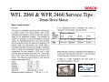
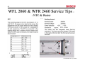
WFL 2060 & WFR 2460 Service Tips - Drum Drive Motor
HINT: Note “RPM”
is the European
symbol for RPM.
1st Edition/Revision 5 (1/20/04)
45
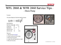
WFL 2060 & WFR 2460 Service Tips - Drain Pump
60
80 - 94
1.0
Hz
Ω
m
1st Edition/Revision 5 (1/20/04)
46
WFL 2060 & WFR 2460 Service Tips - NTC & Heater
23.2 - 29.4Ω
1st Edition/Revision 5 (1/20/04)
47
WFL 2060 & WFR 2460 Service Tips - Door Lock
1st Edition/Revision 5 (1/20/04)
48
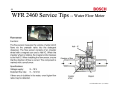
WFR 2460 Service Tips -- Water Flow Meter
1st Edition/Revision 5 (1/20/04)
49
WFR 2460 Service Tips -- Mechanical &
Analog Pressure Switches
The water level (pressure switch) system consists of a mechanical
pressure switch and an analog pressure switch.
Mechanical
Pressure
Switch
Analog
Pressure
Switch
Mechanical Pressure Switch
The mechanical pressure switch (orange) has (3) switching
positions:
•
•
•
Water level < level 1
Water heating level
Overflow level
Analog Pressure Switch
The analog pressure switch (black) determines the different water
levels in the various wash programs. It is piezo-electric (pressure on
it generates a voltage) and generates between 0.5 - 3.5 VDC.
HINT: Its not helpful to measure the analog pressure
switch voltage because its shown on the digital
display while the washer is in the test program.
1st Edition/Revision 5 (1/20/04)
50
WFR 2460 Service Tips -- Polinox Outer
Drum (Tub)
POLINOX TUB
Lifecycle Test
2,500 washes = 10 years
Highest spin 300 consecutive times (wash-spin, wash-spin, etc. have tested up to 900 wash-spin cycles)
Heat Resistant Up to 130°C (266°F)
Stability
Dropped from a great height, won’t dent like Stainless Steel
Used on Mercedes-Benz bumper
•Reinforced with glass fiber
•Extraordinary strength
•Very reliable
•Vibrates less/ less noisy
•Fewer parts
•Lower weight
1st Edition/Revision 5 (1/20/04)
51
WFR 2460 Service Tips -- Low Spin Speeds
If the WFR 2460 control doesn’t allow spin speeds > 800 RPM, then
the Reduced Ironing setting has been turned on.
HINT: To exit the Reduced Ironing mode:
L When Start/Pause indicating light
flashes red, press Menu button until
Reduced Ironing screen appears.
L Press Select button until Reduced
Ironing has been turned off.
1st Edition/Revision 5 (1/20/04)
52
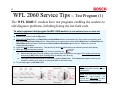
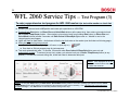
WFL 2060 Service Tips -- Test Program (1)
The WFL 2060UC washers have test programs enabling the washers to
self-diagnose problems, including listing the last fault code.
To enter component test program for WFL 2060 washers (to test individual parts or check last
wash fault):
♦ Rotate cycle selector knob to Off position.
♦ Push and hold Start button (or Rinse Plus and Quick Wash buttons at the same time), then rotate cycle selector knob
ccw to Permanent Press Cold position. After rotating cycle selector knob, keep holding Start button (or Rinse Plus and
Quick Wash buttons) at least 3 seconds until Door locked & Rinse/Spin lights come on. Washer is now in the
component test program.
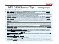
♦ Lights will flash for wash faults below. Fault shown will be the last fault code on the washer (see fault chart below).
♦ When test program has been entered:
Door locked
Rinse/Spin
♦ Door locked & Rinse/Spin lights will come on (and stay on).
Wash
♦ Select individual parts to test by rotating cycle selector knob as shown on next page. Don’t rotate cycle selector
knob through Off position while selecting tests (so washer won’t shut off).
♦ Once part to test has been selected, start test by pushing Start button. Push Start button again to end any test
(except for rotating cycle selector or spin speed knob to end motor test).
♦ To exit test program, push Start button.
NOTE: Fault displayed will be 1st fault
that occurred since last time washer
was turned on.
NOTE: Door locks for all water fill and
drain tests.
Door unlocks ~ 30
seconds after drain pump test ends
(after all water has been drained).
1st Edition/Revision 5 (1/20/04)
53
WFL 2060 Service Tips -- Test Program (2)
Test parts individually as follows:
♦ Motor – To start test, rotate cycle selector knob to Regular/Cotton Hot (not through Off position), then push Start button. To end test,
rotate cycle selector knob out of Regular/Cotton Hot position or rotate spin speed knob.
During test, motor turns drum counterclockwise for 6 seconds (@ 50 RPM), pauses for 2 seconds & turns drum clockwise for 4 seconds.
Drain pump comes on while drum is checked for imbalance and motor turns drum clockwise gradually to top speed, slows it down and stops
it (Rinse/Spin light turns off when max. speed reached). Test ends automatically after ~ 3 minutes.
♦ Drain pump – To start test, rotate cycle selector knob to Temp Boost (not through Off position), then push Start button. To end test, push
Start button again (since test doesn’t end). Drain pump runs -- listen for drain pump running or look for water draining from washer.
♦ Heater – To start test, rotate cycle selector knob to Power Temp Boost (not through Off position), then push Start button. To end test,
push Start button again (since test doesn’t end quickly). Water fills to water level 1 (heating level) and is heated to maximum temperature.
To save time, measure current draw into washer (over black wire to surge protector) after water has completely filled -- if ~ 7A, then heater
has come on and is heating normally.
HINT: Water doesn’t automatically drain for water filling tests such as heater, hot water valve and all dual cold water valve tests.
Door locked
Use drain pump test to drain water before running next test….To save time running
water valve tests (since water doesn’t stop filling),
Rinse/Spin
Wash
do visual check of water filling into dispenser, then push Start button to end test.
♦ Hot water valve – To start test, rotate cycle selector knob to Spin (not through Off position), then push Start button. Water. To end test,
push Start button again (since water doesn’t stop filling). Do visual check by pulling dispenser door slightly (to avoid splashing) to view water
flowing into left side of dispenser.
♦ Dual cold water valve (Pre-wash & Wash) – To start test, rotate cycle selector knob to Soak (not through Off position), then push
Start button. To end test, push Start button again (since water doesn’t stop filling). Do visual check by pulling dispenser door slightly (to
avoid splashing) to view water flowing into center & right side of dispenser.
♦ Dual cold water valve (Wash) – To start test, rotate cycle selector knob to Drain (not through Off position), then push Start button. To
end test, push Start button again (since water doesn’t stop filling). Do visual check by pulling dispenser door slightly (to avoid splashing) to
view water flowing into left side of dispenser.
♦ Dual cold water valve (Pre-wash) – To start test, rotate cycle selector knob to Hand Washables Warm (not through Off position), then
push Start button. To end test, push Start button again (since water doesn’t stop filling). Do visual check by pulling dispenser door slightly
(to avoid splashing) to view water flowing into right side of dispenser.
♦ Indicating lights – To start test, rotate cycle selector knob to Hand Washables Cold or Delicates Warm (not through Off position), then
push Start button. To end test, push Start button again (since test doesn’t end). Wash light comes on for 3 seconds, then Rinse/Spin light
comes on for 3 seconds and then Door locked light comes on. Door locked light won’t go out if door still locked. 1st Edition/Revision 5 (1/20/04)
54
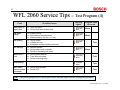
WFL 2060 Service Tips -- Test Program (3)
To enter comprehensive test program for WFL 2060 washers (to test entire washer or check last
wash fault):
♦ Rotate cycle selector knob to Off position and rotate spin speed knob to 1000 RPM.
♦ Push and hold Start button (or Rinse Plus and Quick Wash buttons at the same time), then rotate cycle selector knob
cw to Power Temp Boost position. After rotating cycle selector knob, keep holding Start button (or Rinse Plus and
Quick Wash buttons) at least 3 seconds until Door locked & Rinse/Spin lights come on. Washer is now in the
comprehensive test program.
♦ Lights will flash for wash faults -- fault shown will be the last fault code on the washer (see fault chart on following page).
♦ When test program has been entered:
Door locked
Rinse/Spin
♦ Door locked & Rinse/Spin lights will come on (and stay on).
Wash
♦ See chart on 5th test program page for test sequence.
♦ Test ends automatically (after ~ 2 minutes, 20 seconds when Door locked & Rinse/Spin lights come on) and
automatically restarts. To end test (at any time), rotate cycle selector knob out of Power Temp Boost position (to any
position). If a fault has occurred during test, check fault chart to determine failed part.
NOTE: Fault displayed will be 1st
fault that occurred since last time
washer was turned on.
NOTE: Do not push Start button (or Rinse Plus & Quick Wash buttons) within 5 seconds of rotating cycle selector knob to Power
Temp Boost position while selecting comprehensive test program or while test is restarting. If so, individual part (component) test
program will begin -- use Start button to manually advance through each step.
1st Edition/Revision 5 (1/20/04)
55
WFL 2060 Service Tips -- Test Program (4)
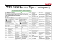
Fault
Possible Causes
Flashing
Lights
Door open or
won’t lock
Door left open.
Faulty door latch or door lock.
Door locked
Rinse/Spin
Wash
No water
filling
Water shut off.
Inlet strainer filters blocked.
Water pressure too low (< 1 bar)
Door locked
Rinse/Spin
Wash
No heating
Faulty heater.
Voltage too low.
Excessive scale on heating element.
Door locked
Rinse/Spin
Wash
Blocked sensor.
Faulty water level controller.
Faulty or blocked drain pump.
Door locked
Rinse/Spin
Wash
Motor won’t
run
Faulty speed control.
Triac short-circuited.
Faulty reversing relay.
Door locked
Rinse/Spin
Wash
Overheating
Faulty control module.
Door locked
Rinse/Spin
Wash
NTC failed
(short or open
circuited)
Faulty wire harness.
Faulty NTC.
Door locked
Rinse/Spin
Wash
No draining
Program Fault
Occurred
Wash
Wash
Test
Wash
Test
Test
Test
HINT: Using the test program can cut down repair times & eliminate repeat calls from misdiagnosing problems.
1st Edition/Revision 5 (1/20/04)
56
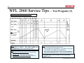
WFL 2060 Service Tips -- Test Program (5)
Comprehensive Test Sequence Chart
HINT: “n” = spin
speed & nmax =
max. spin speed
of 1000 RPM.
HINT: Rinse/Spin light goes out when max. speed of
1000 RPM is reached.
Both Door locked and
Rinse/Spin lights come on when test has ended.
HINT: Before leaving, make sure door isn’t locked. To drain washer to
open locked door (locked during wash or test):
•
Exit test program by turning washer off. Turn washer on, then rotate
cycle selector knob to Drain and push Start button.
HINT: Water valves are tested in order:
•
•
•
Left side of cold water valve (Pre-wash) – flows into right
side of dispenser.
Hot water valve – flows into left side of dispenser.
Left & right sides of cold water valve (Wash) – flows into
right side & center of dispenser.
•
Door can be opened after washer drains and Door locked light
flashes (Door locked light flashes ~ 2 minutes after washer drains).
To exit test program (from any test), turn unit off by pressing
"ON/OFF" button.
1st Edition/Revision 5 (1/20/04)
57
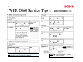
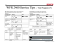
WFR 2460 Service Tips -- Test Program (1)
The WFR 2460UC washers have test programs enabling the washers to self-diagnose
problems, including listing the last 8 fault codes.
Rotate selector switch
to Off position. Press &
hold Menu & Select
buttons (located under
display), then rotate
selector switch ccw to
Permanent Press Cold
until display comes on. See next page for error codes.
” = drum speed (RPM) & “n” = pressure
NOTE: “
switch reading.
HINT: Push Menu
button
to
scroll
through all tests to
select desired test.
Red light on Start/
Pause button flashes
to show tests can be
selected. When tests
are started, red light
stays on constantly.
Push Menu to exit
test & select more
tests.
Cold water valve
Hot water valve
Water
levels
…...
Rotate selector switch
to Off position.
(cw)
(ccw)
1st Edition/Revision 5 (1/20/04)
58
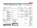
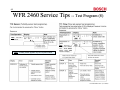
WFR 2460 Service Tips -- Test Program (2)
The last 8 fault codes are stored & displayed!
HINT: # of errors
reads “0” for faults
which didn’t occur.
Look at # of errors,
not error #, to see
if faults occurred.
HINT: Scroll thru all errors
to check if any occurred.
1st Edition/Revision 5 (1/20/04)
59
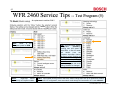
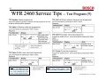
WFR 2460 Service Tips -- Test Program (3)
HINT: Do not use
this test as it
applies to European
models
requiring
VDE safety testing.
NOTE: Test takes ~ 1
minute, 20 seconds to
complete.
HINT: Using the test program can greatly cut down repair times &
eliminate repeat calls from misdiagnosing problems.
NOTE: “
” = drum speed (RPM) & “n” = pressure
switch (analogue sensor) reading.
1st Edition/Revision 5 (1/20/04)
60
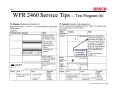
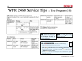
WFR 2460 Service Tips -- Test Program (4)
HINT:
Start/Pause light
turns yellow when
drum speeds up
to 1200 RPM and
slows down.
NOTE: Test takes > 10 minutes to run.
HINT: “RPM” is
European symbol
RPM.
the
for
1st Edition/Revision 5 (1/20/04)
61
WFR 2460 Service Tips -- Test Program (5)
- for replacement modules ONLY
Select
HINT:
“RPM”
is
the
European symbol for RPM.
NOTE:
“Aqua-Stop” feature
appears only on European models.
HINT: This test shows washer
configuration
(42010011),
meaning max. spin speed is
1200 RPM, it uses hot water
and
doesn’t
have
the
European Aqua-Stop feature.
Whenever control modules are
replaced, scroll through all
numerals & select 42010011
for U.S. units.
Note OEM
washers are preset and model
coding CANNOT be changed.
HINT: If spin speed cannot go above 800 RPM, washer coding wasn’t set up on replacement module.
To choose U.S. configuration, enter test mode & scroll through all 8 numerals to U.S. code 42010011.
1st Edition/Revision 5 (1/20/04)
62
WFR 2460 Service Tips -- Test Program (6)
(~ 50 sec.)
•Power Wash
•Rinse Plus
•Quick Wash
P01 for Regular/Cotton
Cold).
Select
(when held
down)
HINT: Test takes
~ 50 seconds to
run.
(when held
down)
1st Edition/Revision 5 (1/20/04)
63
WFR 2460 Service Tips -- Test Program (7)
HINT:
Display
shows T8:NIVEAU1
HINT:
Display
shows T9:NIVEAU2
HINT: “W controller” is the mechanical pressure switch.
HINT: Start/Pause light turns yellow when water reaches ND level.
1st Edition/Revision 5 (1/20/04)
64
WFR 2460 Service Tips -- Test Program (8)
HINT: Test runs ~
15 seconds.
HINT: Turbidity sensor appears only on European models.
HINT: Test runs ~ 1
minute, but doesn’t
end.
Press Menu
button when U05
shows on display.
1st Edition/Revision 5 (1/20/04)
65
WFR 2460 Service Tips -- Test Program (9)
HINT: To save time with Tests
T13 - T17, press Menu to stop test
when the washer stops filling (tests
T13 - T16) or draining (T17). Run
Test 17 to drain washer if needed.
HINT: Tests T13 - T16 fill until n256
pressure switch reading appears. When
display reads n256, press Menu to stop test.
1st Edition/Revision 5 (1/20/04)
66
WFR 2460 Service Tips -- Test Program (10)
HINT: To save time with Test T18,
press Menu to stop testing after
the temperature has gone up
several degrees, confirming the
washer is heating OK.
NOTE: On Test T18, the water
level rises until NH, which is the
heating water level.
HINT: Start/Pause button light:
• Flashes red when tests can be selected or scrolled through.
• Stays red continually when tests are running.
• Stays yellow continually when drum is accelerating/running at max.
speed (during drum motor test) or has reached ND water level (~ n152
pressure switch reading -- when water is draining, yellow light turns red
~ n094 pressure switch reading).
• Flashes yellow when drum is slowing down from 1200 RPM max. speed
during drum motor test.
1st Edition/Revision 5 (1/20/04)
67
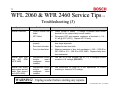
WFL 2060 & WFR 2460 Service Tips -Troubleshooting of Minor Faults (Customer Self-Help)
.
.
.
1st Edition/Revision 5 (1/20/04)
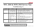
68
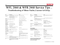
WFL 2060 & WFR 2460 Service Tips -Troubleshooting of Minor Faults (Customer Self-Help)
1st Edition/Revision 5 (1/20/04)
69
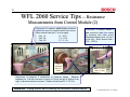
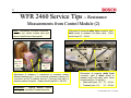
WFL 2060 Service Tips -- Resistance
Measurements from Control Module (1)
Disconnect & measure blue 2pin connector (with blue
wires) to measure drain pump.
Pump should read ~ 80 - 94 Ω
Disconnect & measure white 5-pin connector (with 3
black wires) to measure dual cold water valve. Valve
should read (pin 1 is at bottom):
• Main wash (pins 1-3): 2.7 - 4.5 kΩ
• Prewash (pins 1-5):
2.7 - 4.5 kΩ
Top
Top
1
Disconnect & measure tan 3-pin connector (with 2
black wires) to measure NTC. NTC should read:
• 20ºC (68ºF):
5.4 - 6.5 kΩ
• 30ºC (86ºF):
3.5 - 4.3 kΩ
• 40ºC (104ºF): 2.3 - 2.9 kΩ
Disconnect & measure tan 3-pin
connector (with 2 black wires) to
measure hot water valve. Valve
should read 2.7 - 4.5 kΩ.
WARNING! Unplug washer before making any resistance measurements.
1st Edition/Revision 5 (1/20/04)
70
WFL 2060 Service Tips -- Resistance
Measurements from Control Module (2)
Disconnect & measure white 6-pin connector
(with blue wires) to measure drum drive motor.
Motor should read (pin 1 is at far right):
• Pins 1-2:
14 - 35 Ω
• Pins 3-4:
1.5 - 10 Ω
• Pins 5-6:
0.7 - 2.1 Ω
1
Disconnect & measure white 3pin connector (with blue wires)
to measure door latch motor.
Measure between pins 1-2 (pin 1
at far left). Motor should read ~
500 - 1500 Ω.
1
Pink
connector
with pink
wires
1
1
Black connector
with pink wire
Disconnect & measure 2 connectors to measure heater. Measure
between pin 1 (far left connector in group of 7 pins) and pin 2 (2nd pin from
right) of pressure switch connector. Heater should read 23.2 - 29.4 Ω.
WARNING! Unplug washer before making any resistance measurements.
1st Edition/Revision 5 (1/20/04)
71
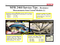
WFR 2460 Service Tips -- Resistance
Measurements from Control Module (1)
Disconnect & measure white 6-pin connector (with blue wires) to
measure drum drive motor. Motor should read (pin 1 is at far right):
• Pins 1-2:
14 - 35 Ω
• Pins 3-4:
1.5 - 10 Ω
• Pins 5-6:
0.7 - 2.1 Ω
Disconnect & measure blue 2-pin
connector (with blue wires) to
measure drain pump. Pump should
read ~ 80 - 94 Ω.
1
1
Disconnect & measure white 3-pin
connector (with blue wires) to
measure door latch motor. Measure
between pins 1-2 (pin 1 at far left).
Motor should read ~ 211 - 259 Ω.
1
Disconnect & measure white 2-pin
connector (with black wires) to
measure NTC. NTC should read:
• 20ºC (68ºF):
5.4 - 6.5 kΩ
• 30ºC (86ºF):
3.5 - 4.3 kΩ
• 40ºC (104ºF):
2.3 - 2.9 kΩ
WARNING!
Unplug washer
before making
any resistance
measurements.
1st Edition/Revision 5 (1/20/04)
72
WFR 2460 Service Tips -- Resistance
Measurements from Control Module (2)
HINT If necessary to access connectors,
carefully pry control module tabs and
remove module from fascia panel.
Disconnect & measure white 2-pin connector (with
black wires) to measure hot water valve. Valve
should read 2.7 - 4.5 kΩ.
1
1
Pink
connector
with pink
wires
Connector
with pink
wire
Disconnect & measure 2 connectors to measure heater.
Measure between pin 1 (1-pin connector at bottom of group of 3
connectors at left of module) and pin 2 (2nd pin from right) of
pressure switch connector. Heater should read 23.2 - 29.4 Ω..
WARNING!
Unplug washer before
making any resistance measurements.
Disconnect & measure white 5-pin
connector (with 3 black wires) to
measure dual cold water valve. Valve
should read (pin 1 is at right):
• Main wash (pins 1-3): 2.7 - 4.5 kΩ
• Prewash (pins 1-5):
2.7 - 4.5 kΩ
1st Edition/Revision 5 (1/20/04)
73
WFL 2060 & WFR 2460 Service Tips - Troubleshooting (1)
Symptom
Washer won’t start.
Problem
Electricity is disconnected
or has been turned off.
Cycle selector knob or
control module has failed.
Make sure washer is connected to an appropriate 240V, 60 Hz
circuit (according to local codes). Turn on electricity.
Control module has onboard cycle selector knob. Check
voltage output to water inlet valves and drum motor (when
they’re energized). If no voltage, replace faulty control module.
Water supply turned off.
Turn on water supply.
Water inlet hose filters
(strainers) blocked.
Check water inlet hose filters. Clean if dirty. Replace filters if
damaged.
Water pressure too low.
Control
module
has
failed.
Water inlet valve(s) has
failed.
Check incoming water pressure.
Check voltage output to water inlet valves (when they’re
energized). If no voltage, replace faulty control module.
Measure resistance of water inlet valves (~ 2.7 – 4.5 kΩ).
Replace inlet valve(s), if faulty.
Drain pump or motor
protector has failed.
Control
module
has
failed.
Washer won’t fill.
Washer won’t drain.
Solution
Disconnect drain pump and measure resistance at connector
(~ 80 – 94 Ω). Replace drain pump if faulty.
Check voltage output to drain pump when it’s energized). If no
voltage, replace faulty control module.
WARNING! Unplug washer before starting any repairs.
1st Edition/Revision 5 (1/20/04)
74
WFL 2060 & WFR 2460 Service Tips -Troubleshooting (2)
Symptom
Drum won’t rotate.
Washer won’t heat.
Problem
Solution
Drum rear bearing
has failed.
Check how drum rotates. If drum wobbles or won’t move,
replace faulty rear bearing.
Motor drive circuit
(Triac) has failed.
Check voltage at motor connectors when motor is energized.
If low or no voltage, replace faulty control module.
Drum drive motor
has failed.
Check voltage at motor connectors when motor is energized.
If ~ 240V, replace faulty drum motor.
Reversing relays
have failed.
Check voltage at motor connectors when motor is energized.
If voltage doesn’t reverse, replace faulty control module.
Heater has failed.
Disconnect heater and measure resistance at terminals (~
23.2 – 29.4Ω). Replace heater if faulty.
NTC has failed.
Disconnect NTC and measure resistance at terminals (~ 5.4
– 6.5 k Ω @ 20ºC (68ºF)). Replace NTC if faulty.
Heater is covered
with scale.
If possible, remove & clean heater. If not, replace it.
Voltage too low.
Control
module
has failed.
Have an electrician check the house wiring and the wiring to
the washer to make sure it is 240 volts.
Check voltage output to drain pump when it’s energized). If
no voltage, replace faulty control module.
WARNING! Unplug washer before starting any repairs.
1st Edition/Revision 5 (1/20/04)
75
WFL 2060 & WFR 2460 Service Tips -Troubleshooting (3)
Symptom
Washer overheats.
Problem
Solution
Control module has
failed.
Check voltage to heater. If voltage is present when heater
shouldn’t be on, replace faulty control module.
NTC failed.
Disconnect NTC and measure resistance at terminals (~ 5.4 –
6.5 kΩ @ 20ºC (68ºF)). Replace NTC if faulty.
Door isn’t
properly.
closed
Close door securely. If door won’t latch, check door latch and
door hinge alignment.
Door latch is broken.
Replace broken door latch.
Door lock has failed.
Measure resistance of door lock mechanism (~ 500 – 1500 Ω for
WFL 2060 or 211 – 259 Ω for WFR 2460). Replace faulty door
lock mechanism.
Washer won’t spin
over
800
RPM
(WFR 2460).
Replacement control
module
wasn’t
configured
when
installed.
Use test T5 on test program (pp. 43, 61) to configure control
module to U.S. settings (42010011).
Washer has wrong
wash cycles and hot
water inlet doesn’t
work (WFL 2060).
Replacement control
module
wasn’t
configured
when
installed.
Use instructions on page 42 to set dipswitches on control
module (p.c. board) to U.S. settings.
Door won’t lock.
WARNING! Unplug washer before starting any repairs.
1st Edition/Revision 5 (1/20/04)
76
WFL 2060 Service Tips -- WFL 2060 Not Running
NOTE: Occasionally, WFL2060 washers have been set up for sales
WFL2060 drain pump is
located at washer right
front
corner
(photo
viewing rear of washer)
demonstration and not reconfigured for normal use when they were sold.
HINT: When repairing WFL2060 washers that won’t run at all, check the
drain motor first to see if its connected.
NOTE: WFL2060 washers cannot be set up for sales demonstration
mode since the control senses the drain motor during start up.
Push on white (or gray) drain
pump electrical connector (if
it has been pulled off).
HINT: If WFL2060 washers have been set up for sales demonstration
and not reconfigured for normal use, all lights will turn on and washers
won’t run. If this occurs, check the drain motor first.
HINT: If electrical tape has been used on the washer, carefully clean off
all tape adhesive residue to insure good electrical connections.
HINT: When repairing WFL2060 washers that won’t run at all, if the drain
IMPORTANT
Shipping bolt
locations
•
•
•
motor has been disconnected for sales display, please check the
following:
Make sure the drain motor is reconnected.
Make sure the fuscia label has been removed from the rear of the the
washer.
Make sure the shipping bolts have been removed.
1st Edition/Revision 5 (1/20/04)
77
WFL 2060 Service Tips -- Fascia Panel Parts
Surge
suppressor
240V, 15A,
3-pronged
plug with
cord (NEMA
6-15P )
NOTE:
Complete fascia panel
366766
includes
knobs
and
dispenser drawer gasket. Dispenser
door front 484011 is not included
and must be bought separately.
Use & Care Manual
Cycle Chart
To hot
water inlet
valve
To
To drum
drive motor
To pressure switch
To dual cold water inlet valve
NOTE: Parts are subject
to change without notice.
To obtain an updated
parts
list
(updated
monthly), please purchase
a parts CD subscription.
1st Edition/Revision 5 (1/20/04)
78
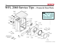
WFL 2060 Service Tips -- Frame & Door Parts
Shipping
bolts
NOTE: Parts are subject
to change without notice.
To obtain an updated
parts
list
(updated
monthly), please purchase
a parts CD subscription.
Shipping
bolts
Door latch
mechanism
Door latch
assy.
Wrench
Optional leveling leg
securing kit (same as
WMZ 2200)
1st Edition/Revision 5 (1/20/04)
79
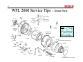
WFL 2060 Service Tips -- Drum Parts
Concrete top
counterweight
NOTE:
Parts are
subject
to
change
without notice.
To
obtain an updated parts
list (updated monthly),
please
purchase a
parts CD subscription.
Polinox
rear outer
drum
ss inner
drum
Polinox front
outer drum
Drive
belt
Concrete front counterweight
Drum
drive
motor
Heater
NTC
1st Edition/Revision 5 (1/20/04)
80
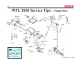
WFL 2060 Service Tips -- Pump Parts
Water inlet
valves (hot
& dual cold)
Pressure
switch
Cold
Water inlet
hoses (hot
& cold)
Drain
reservoir
Hot
Dispenser
Air dome
NOTE:
Parts are
subject
to
change
without notice.
To
obtain an updated parts
list (updated monthly),
please
purchase a
parts CD subscription.
Ball check
sump
Drain pump
and trap
1st Edition/Revision 5 (1/20/04)
81
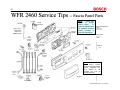
WFR 2460 Service Tips -- Fascia Panel Parts
Surge
suppressor
240V, 15A, 3pronged plug
with cord
(NEMA 6-15P )
Control
module
NOTE:
Parts are
subject
to
change
without notice.
To
obtain an updated parts
list (updated monthly),
please purchase a
parts CD subscription.
Use & Care Manual
Cycle Chart
To
analog
pressure
switch
To dual
cold water
inlet valve
366771
To
To main
pressure
switch
NOTE:
Complete fascia
panel 366771 includes
knob and dispenser drawer
gasket.
Dispenser door
front
484013
is
not
included and must be
bought separately.
To drum
drive
motor
To hot
water inlet
valve
To flow meter
1st Edition/Revision 5 (1/20/04)
82
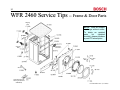
WFR 2460 Service Tips -- Frame & Door Parts
Shipping
bolts
NOTE: Parts are subject
to change without notice.
To obtain an updated
parts
list
(updated
monthly), please purchase
a parts CD subscription.
Shipping
bolts
Door latch
mechanism
Door latch
assy.
Wrench
Optional leveling leg
securing kit (same as
WMZ 2200)
1st Edition/Revision 5 (1/20/04)
83
WFR 2460 Service Tips -- Drum Parts
Polinox
rear outer
drum
Concrete top
counterweight
NOTE: Rear outer drum
gasket & screws are not
available separately)
ss inner
drum
Polinox front
outer drum (with
gasket & bolts)
Drive belt
NOTE: When replacing rear
outer drum, replace front outer
drum at the same time.
Concrete front counterweight
Drum
drive
motor
NOTE: Parts are subject
to change without notice.
To obtain an updated
parts
list
(updated
monthly), please purchase
a parts CD subscription.
Heater
NTC
1st Edition/Revision 5 (1/20/04)
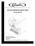
84
WFR 2460 Service Tips -- Pump Parts
Main pressure
switch
Cold
Analog pressure
switch
Hot
Hoses
Hoses
Drain
reservoir
Water inlet
valves (hot
& dual cold)
Dispenser
Water inlet
hoses (hot
& cold)
NOTE:
Parts are
subject to change
without notice. To
obtain an updated
parts list (updated
monthly),
please
purchase a parts CD
subscription.
Air dome
Ball check
sump
Drain pump
and trap
1st Edition/Revision 5 (1/20/04)