1
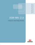
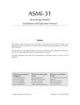
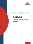
MBE Family Installation and Operation Manual
Chapter 2 Installation
I
O
POWER
TO V.35 LINE
AUI
100-230 VAC
Figure 2-5. MBE Rear Panel, V.35 Connector
I
O
POWER
AUI
TO RS-232/V.24
100-230 VAC
I
O
POWER
AUI
100-230 VAC
LINK 2 RS-232/V.24
LINK 1 RS-232/V.24
Figure 2-6. MBE Rear Panel, V.24 Connector
Connecting the Line
A connector is provided to connect each interface to the communication link.
To connect the line:
•
See Appendix A for LINK connector pin assignments. Note that the X.21 and
V.36 connections are provided by adapter cables to the RS-530 (25-pin
connector) on the MBE rear panel.
Interface cards are interchangeable. Consult your RAD dealer for details.
Connecting the LAN
To connect to the LAN:
•
Caution
Use a standard AUI (15-pin, D-type), 10Base2 (BNC) or 10BaseT (RJ-45)
connector, provided by RAD.
To ensure compliance with electromagnetic compatibility (EMC) requirements, it is
recommended that you only use shielded data cables with this product. Make sure
that the shield is connected to the metallic hood of the cable connector.
For units with V.35 ports, in order to protect against electrostatic discharge (ESD)
into the port, use a connector with an overlapping hood that completely covers
the pin connection.
2-8
Order from: Cutter Networks
Installation and Setup
Ph:727-398-5252/Fax:727-397-9610
www.bestdatasource.com