1
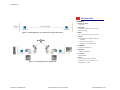
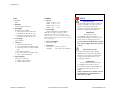
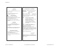
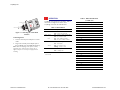
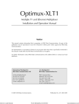
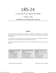
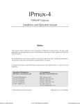
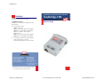
TinyBridge-100
Installation and Operation Manual
ORDERING
TINYBRIDGE-100/#/$
Miniature remote Fast Ethernet bridge
TINYBRIDGE-100/4W/$
Miniature remote Fast Ethernet bridge with 4-wire
WAN interface
#
Specify WAN interface:
V24 for V.24/RS-232
V35F for V.35 (female adapter cable supplied)
V35M for V.35 (male adapter cable supplied)
V36 for V.36 (adapter cable supplied)
530 for RS-530
X21F for X.21 (female adapter cable supplied)
X21M for X.21 (male adapter cable supplied)
$
Specify AC for 100–240 VAC switching power
supply with integral AC connector
(may be ordered separately as P/S-AC/5/1200)
TinyBridge-100
Miniature Remote Fast
Ethernet Bridge
www.rad.com
International Headquarters
U.S. Headquarters
24 Raoul Wallenberg Street
900 Corporate Drive
Tel Aviv 69719, Israel
Mahwah, NJ 07430
Tel: (972) 3-6458181
Tel: (201) 529-1100
Fax: (972) 3-6498250, 6474436
Toll free: 1-800-444-7234
Email: [email protected]
Fax: (201) 529-5777
Email: [email protected]
386-100-02/05
Specifications are subject to change without prior notice.
© 1993–2005 RAD Data Communications Ltd.
Order from: Cutter Networks
Ph: 727-398-5252 / Fax: 727-397-9610
www.bestdatasource.com
TinyBridge-100
FEATURES
• High performance miniature remote
bridge for Fast Ethernet extension
• Wire-speed WAN throughput:
19,700 pps at 10 Mbps
• 10/100BaseT interface
• Synchronous WAN interfaces: V.24,
V.35, V.36, RS-530, X.21, or 4-wire
modem
• Two priority queues according to
802.1p or IP ToS bits
• Fault propagation of WAN error
conditions to LAN port
• Automatic MDIX support
• Compatible with applicable parts of
IEEE 802.3
DESCRIPTION
• TinyBridge-100 is a high performance,
remote, self-learning Ethernet/Fast Ethernet
bridge. Its small size and low cost make it
ideal for sensitive bridging applications, or
as a LAN extender over synchronous WAN.
LAN INTERFACE
• TinyBridge-100 is available with a
10/100BaseT interface. The interface
operates in full or half duplex Ethernet
topologies.
• TinyBridge-100 supports a packet length of
up to 1536 bytes.
• Automatic MDIX allows using straight or
crossed cables for the LAN connection.
• MAC addresses of the LAN to which the
unit is connected are automatically learnt.
Only those frames destined for the remote
LAN are forwarded. The LAN table stores
up to 2048 addresses and is updated
automatically.
• MAC address filtering can be disabled,
allowing all traffic to flow over the WAN link
• TinyBridge-100 has two queues for
handling priority, determined in the
following order:
If the packet received is an Ethernet tag
frame, TinyBridge-100 marks the packet
according to the tag priority (0–7).
0–3: low priority queue
4–7: high priority queue
Order from: Cutter Networks
Ph: 727-398-5252 / Fax: 727-397-9610
Otherwise, TinyBridge-100 marks the
packet according to IP-ToS priority (0–7).
0–3: low priority queue
4–7: high priority queue
Untagged and non-IP frames enter the
low priority queue.
Frames egress from the queues with a 1:2
ratio, two frames with high priority, one
frame with low priority.
• Flow control for full duplex and
backpressure for half duplex are supported.
The buffer holds up to 120 frames.
WAN INTERFACE
• A selection of synchronous WAN interfaces
is available:
V.24/RS-232
V.35
V.36/RS-449
X.21
RS-530.
• A fault on the WAN can be propagated if
fault propagation is enabled; the
TinyBridge-100 shuts down the link and
forces a router to trace another route.
• TinyBridge-100 operates over synchronous
links at data rates of up to 10 Mbps. An
external clock can be supplied for
operation at other bit rates.
www.bestdatasource.com
TinyBridge-100
FLAG
DATA
CRC
FLAG
APPLICATIONS
1
60–1532
2
1
Figure 1. TinyBridge-100 Frame Structure
• TinyBridge-100 WAN interface operates in
DTE mode. This means it accepts receive
and transmit clocks. The timing diagram is
shown in Figure 2.
Rx Data
Rx Clock
tSETUP tHOLD
5ns
5ns
Figure 3. Bridging and Extending Ethernet over Baseband Modems
Tx Data
Tx Clock
tDELAY
9ns
Figure 2. Receive and Transmit Clock
Timing Diagrams
Figure 4. Bridging Ethernet over Multiplexed E1/T1 Links
Order from: Cutter Networks
Ph: 727-398-5252 / Fax: 727-397-9610
www.bestdatasource.com
TinyBridge-100
SPECIFICATIONS
ETHERNET
• Frame size (max)
1536 bytes
• LAN Table
2048 MAC addresses with 5-minute
automatic aging
Figure 5. Extending Ethernet over 4-Wires in the Campus Enviroment
• Buffer
Up to 120 frames for 64-byte frames
• Latency
With LAN rate 100 Mbps, WAN rate
10 Mbps:
66 μs for 64-byte frames
1400 μs for 1536-byte frames
• Compliance
Conforms to IEEE 802.3
• Data Rate
10 Mbps, 100 Mbps
• Connectors
Shielded RJ-45
• Cable
Figure 6. Broadcasting Data over Satellite Link
Order from: Cutter Networks
Ph: 727-398-5252 / Fax: 727-397-9610
To comply with electromagnetic
regulations, it is recommend to use
shielded Cat. 5 cable.
www.bestdatasource.com
TinyBridge-100
WAN
• Protocol
HDLC
• Data Rate
Up to 10 Mbps synchronous
• Throughput
With WAN rate 10 Mbps:
19700 pps for 64-byte frames and
increment byte data (00, 01, 02, …)
802 pps for 1536-byte frames and
increment byte data (00, 01, 02, …)
• 4-wire Range
700m (2300 ft)
• Connectors
V.24/RS-232, DB-25 female
V.35, 34-pin female via adapter cable
V.36/RS-422, DB-37 female via adapter
cable
RS-530, DB-25 female
X.21, DB-15 female via adapter cable
4-wire: 5-pin terminal block
SAFETY
GENERAL
• Physical
Length:
Width:
Height:
Weight:
69 mm
53 mm
18 mm
30 g
/ 2.7 in
/ 2.1 in
/ 0.7 in
/ 1.0 oz
• Power Supply
External 5 VDC/0.6A regulated adapter
Note: While TinyBridge-100 operates with any
regulated 5 VDC, 600 mA power supply, the CE
approval for the 4-wire versions requires provision of a
grounding path through the use of a power supply with
a three-prong plug.
• Power Consumption
400 mA @ 5 VDC
• Environment
Temperature: 0–50°C (32–122°F)
Humidity:
Up to 90%, non-condensing
Safety Instructions
The exclamation point within an equilateral
triangle is intended to alert the user to the
presence of important operating and
maintenance (servicing) instructions in the
literature accompanying the appliance.
IMPORTANT
North American Users
The TinyBridge-100 is powered by an
external power supply. To reduce the risk of
electric shock, fire and injury to persons:
Use only with a UL-listed and CSA Certified
Class 2 power supply rated 5 VDC, 600 mA
or more.
Instructions de Sécurité
Le point d’exclamation dans le triangle
équilatéral alerte l’utilisateur d’importantes
instructions concernant le fonctionement et
l’entretien mentionées dans le livre qui
accompagne l’appareil.
• Operating Range
Using Cat. 5 UTP cable:
10 Mbps: 500m (1640 ft)
5 Mbps: 700m (2300 ft)
IMPORTANT
Pour les utilisateurs Nord Américains
Le TinyBridge-100 est renforcé par un
transformateur extérieur. Afin de réduire le
risque d’électrocution, de feux ou de
blessure:
Utiliser seulement avec le UL listé et le CSA
Certifié Classe 2 le transformateur de 5
VDC, 600 mA, ou plus.
Order from: Cutter Networks
Ph: 727-398-5252 / Fax: 727-397-9610
www.bestdatasource.com
TinyBridge-100
CAUTION
European Users
To reduce the risk of electric shock, fire and
injury to persons:
Use only with a power supply which
complies with EN 60950.
Sicherheitshinweise
Das Ausrufezeichen innerhalb des
gleichschenkligen Dreiecks soll den Benutzer
auf wichtige Bedienungs- und
Wartungshinweise in der dem Gerät
beiliegenden Dokumentation aufmerksam
machen.
DECLARATION OF CONFORMITY
Mfr. Name: RAD Data Communications Ltd.
Mfr. Address:
declares that the product:
Verwenden Sie nur ein Netzteil, das gemäß
des Standards EN 60950 zugelassen ist.
Telecommunication Safety
The TinyBridge-100 is not intended to be
connected directly to long
telecommunication wires, which are
subjected to strong transient phenomenea
and surges.
Order from: Cutter Networks
TinyBridge-100
Conforms to the following standard(s) or other
normative document(s):
EMC:
EN 55022:1998 - Information
technology equipment, radio
disturbance characteristics, limits and
methods of measurement.
EN 50024:1998 - Information
technology equipment, immunity
characteristics, limits and methods of
measurement.
Safety:
EN 60950:2000 – Safety of
information technology equipment.
ACHTUNG
Europäische Benutzer
Um das Risiko eines elektrischen Schlages
oder Brandes so weit wie möglich zu
vermeiden:
24 Raoul Wallenberg St.
Tel Aviv, 69719,
Israel
Supplementary Information:
The product herewith complies with the
requirements of the R&TTE Directive 1999/5/EC
for wired equipment. The product was tested in
a typical configuration. This declaration is valid
only for products that bear a CE mark.
Tel Aviv, 20 September 2004
Haim Karshen
VP Quality
European Contact: RAD Data Communications
GmbH, Lyoner Strasse 14, 60528 Frankfurt am
Main, Germany
Ph: 727-398-5252 / Fax: 727-397-9610
www.bestdatasource.com
TinyBridge-100
Connecting the LAN Interface
• Connect the user LAN to the RJ-45
connector of TinyBridge-100. Automatic
MDIX allows using straight or crossed
cables for the LAN connection.
INSTALLATION
Configuring TinyBridge-100
1. Identify switches on top panel of TinyBridge-100.
2. Set switches according to Table 1.
Table 1. DIP Switch Settings
Switch
Switch
Identity
Function
Possible Settings
Factory
Setting
1
100
LAN rate
ON – 100 Mbps
ON
OFF – 10 Mbps
2
FDX
LAN duplex mode
ON – Full duplex
ON
Connecting the 4-Wire Interface
ON
Warning: Do not apply power to the TinyBridge-100
until the 4-wire terminal block is connected as
described below.
OFF – Half duplex
3
AN
Autonegotiation mode
ON – Autonegotiation is enabled. Maximum LAN port level is
advertised at 100 Mpbs, full duplex.
OFF – Autonegotiation disabled. Speed and duplex mode are
determined by the 100 and FDX switches.
4
FIL1
LAN Filtering mode.
ON – Only frames destined for another LAN are transmitted
over the WAN
ON
6
FP
FLC2
Fault Propagation
Backpressure/Flow
control
ON – If the CTS (RS-530, V.36, V.35, V.24), or Indication (X.21)
signal is not received at the WAN side or LOS condition is
detected (4-wire), LAN link is shut down.
OFF – LAN link status does not depend on any signal on the
WAN side.
OFF
ON - Backpressure/flow control are enabled for half duplex/full
duplex respectively
ON
OFF - Backpressure/flow control are disabled for half duplex/full
duplex respectively
7
LNG
LONG (for 4-wire
interface version only)
ON – 4-wire link operates at 5 Mbps
OFF – 4-wire link operates at 10 Mbps
OFF
Note 1: Reset TinyBridge-100 to put changes in the filtering mode into effect.
Note 2: Enable autonegotiation to put changes in the flow control mode into effect.
When powering up the TinyBridge-100 with flow control disabled, enabling flow control requires resetting
TinyBridge-100.
Order from: Cutter Networks
1. Remove the protective cover from the
terminal block.
2. Unplug the terminal block from the
TinyBridge-100.
OFF – All frames are transmitted over the WAN
5
Connecting the WAN Interface
• Connect the 25-pin female connector
of the unit to DCE equipment, using the
supplied adapter cables (see Table 3,
Table 4, or Table 5 for pinout details)
Ph: 727-398-5252 / Fax: 727-397-9610
3. Feed the 4-wire cable through the protective
cover and connect the Tx and Rx wires to
their respective terminals, as illustrated in
Figure 7. If the cable is shielded, connect the
shield to the GND terminal.
4. Check that the wires are secure and
reconnect the terminal block to its socket.
5. Place the protective cover in position over
the terminal block.
IMPORTANT: When two 4-wire
TinyBridge-100 units are to be connected
directly, the terminal blocks should be wired
so that the Rx terminals of each
TinyBridge-100 connect to the Tx terminals
of the other unit.
www.bestdatasource.com
TinyBridge-100
ON
LNG
FLC
FP
100
ON
yB
Tin
ri
-10
dge
0
TERMINAL BLOCK
R
PW
N
WA
LAN
100X
FD
AN
FIL
OPERATION
TX
4-WIRE CABLE
TinyBridge-100 operation is automatic. Table 2
shows how to diagnose the status of the
TinyBridge-100 from the LED indicators.
Table 2. LED Indicators
GND
RX
LED
SCREW TERMINAL
Figure 7. Connecting the 4-wire WAN
Interface
WAN Yellow
ON – Activity on WAN (includes idle)
OFF – No activity on WAN
Red1
ON – Error condition on WAN
OFF – No error condition on WAN
LAN
2. Plug in the external power adapter jack to
the TinyBridge-100. The PWR LED lights up
Note: While the TinyBridge-100 operates with any
regulated 5 VDC, 600 mA power supply, the CE
approval requires use of the power supply listed in
Ordering.
Description
ON – Power is connected
OFF – Power is disconnected
Connecting Power
1. Connect external power adapter to a mains
outlet
Color
PWR Green
Green
OFF – No link integrity
ON – Link integrity
Yellow
OFF – No activity on LAN
Blinking – Activity on LAN
100
Green
ON – 100 Mbps LAN
OFF – 10 Mbps LAN
1
4-wire model
Table 3. DB-25 Pin Allocation
(V.24/RS-232)
Pin
Name
1
SHIELD
Type
2
TxD
Output
3
RxD
Input
4
RTS
Output
5
CTS
Input
6
NC
7
GND
8
NC
9
NC
10
NC
11
NC
12
NC
13
NC
14
NC
15
TCLK
16
NC
17
RCLK
18
NC
19
NC
20
NC
21
NC
Input
Input
22
Order from: Cutter Networks
Ph: 727-398-5252 / Fax: 727-397-9610
23
NC
24
NC
25
NC
www.bestdatasource.com
TinyBridge-100
Table 5. DB-25 Pin Allocation
(V.11)
(used for RS-530, X.21, V.36)
Table 4. DB-25 Pin Allocation
(V.35)
Pin
Name
1
SHIELD
Type
Pin
Name
2
TxD-A
Output
1
SHIELD
3
RxD-A
Input
2
TxD-A
Output
RxD-A
Input
Type
4
RTS-A
Output
3
5
CTS-A
Input
4
RTS-A
Output
NC
5
CTS-A*
Input
GND
6
NC
7
GND
8
NC
6
7
8
9
RCLK-B
10
NC
9
RCLK-B
11
NC
10
NC
11
NC
12
TCLK-B
13
NC
14
TxD-B
15
Input
Input
Input
12
TCLK-B
Output
13
CTS-B*
Input
Input
TCLK-A
Input
14
TxD-B
Output
16
RxD-B
Input
15
TCLK-A
Input
17
RCLK-A
Input
16
RxD-B
Input
18
NC
17
RCLK-A
Input
19
NC
18
NC
20
NC
19
RTS-B
21
NC
20
NC
22
NC
21
NC
23
NC
22
NC
24
NC
23
NC
25
NC
24
NC
25
NC
Output
* Indication signal for X.21
Order from: Cutter Networks
Ph: 727-398-5252 / Fax: 727-397-9610
www.bestdatasource.com