1
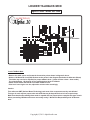
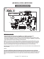
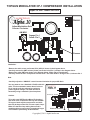
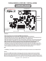
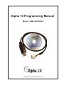
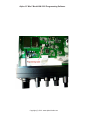
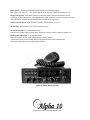
Alpha 10
MAX
10 Meter Amateur Transceiver
MODEL AM-1000
AM/FM/CW/SSB 6 BAND PROGRAMMABLE
1234567890123456789012345678901212345678901234567890123456789012123456789012345678901
1234567890123456789012345678901212345678901234567890123456789012123456789012345678901
1234567890123456789012345678901212345678901234567890123456789012123456789012345678901
1234567890123456789012345678901212345678901234567890123456789012123456789012345678901
1234567890123456789012345678901212345678901234567890123456789012123456789012345678901
1234567890123456789012345678901212345678901234567890123456789012123456789012345678901
1234567890123456789012345678901212345678901234567890123456789012123456789012345678901
SERVICE MANUAL
1234567890123456789012345678901212345678901234567890123456789012123456789012345678901
1234567890123456789012345678901212345678901234567890123456789012123456789012345678901
1234567890123456789012345678901212345678901234567890123456789012123456789012345678901
1234567890123456789012345678901212345678901234567890123456789012123456789012345678901
1234567890123456789012345678901212345678901234567890123456789012123456789012345678901
1234567890123456789012345678901212345678901234567890123456789012123456789012345678901
1234567890123456789012345678901212345678901234567890123456789012123456789012345678901
Downloaded from www.cbradio.nl
Cover Page
LOUDER TALKBACK MOD
Alpha 10 Max - Model AM-1000
4.7K Resistor
Louder TalkBack Mod:
* Remove the radio covers and locate the Connection points shown in diagram A above.
* Solder a 1/4 Watt 4.7K ohm (4700) Resistor to the points in the diagram (See below for Alternate Values)
This Value may need to be adjusted for proper talkback level - (Lower resistor values = lower audio)
Try values between 1.8k through 4.7k to get the desired level of Talkback.
* Power On the Radio and test the increased TalkBack Level.
* If the level is too high or too low, adjust the resistor value accordingly.
Caution:
This radio uses SMT (Surface Mount Technology) and most of the components are tiny and delicate!
This type of work requires proper tools and skills that may be beyond the level of some repair shops.
Make sure that the shop making these mods is capable and has proper tools to complete this type of work
before proceeding. Mistakes and errors are usually costly! - We take No Responsibility and No Guarantees!
Copyright (C) 2011 - alpha10radio.com
Programmable Talkback Feature
Alpha 10 Max - Model AM-1000
Programming the AM-1000 TalkBack Feature (Rev 3.0A Up)
* Press and Hold the FUNC Button for two seconds to enter Programming Mode.
* Press the FUNC Button repeatedly until “TES” or “TNS” appears on the LCD Display.
* Use the Clarifier Control to set these two functions to a On/Off state.
When TES is On, and ECHO is On, The user can hear his voice through the speaker to properly
set the Echo Function. When ECHO is OFF, the Talkback feature will not work in other modes.
Use the Clarifier Control to set this feature On/Off.
When TNS is On, and ECHO is Off, The user can hear his voice through the speaker.
The Talkback feature will work on All Modes to check proper operation and control levels.
Use the Clarifier Control to set this feature On/Off.
Note:
This feature is only available in newer Alpha 10 Max Model AM-1000 (Firmware revision v3.0A up)
When entering the programming mode, press the FUNC Button repeatedly until display shows the
TNS or TES Functions. If these settings are not shown on the display, your firmware version cannot
use this option.
Copyright (C) 2011 - www.alpha10radios.com
Microphone Wiring Diagram
Alpha 10 Max - Model AM-1000
+ 5VDC
Diagram A (Inside Radio)
Chan Up/Dn
Transmit PTT
P2 Key
P1 PTT
Mic Board (Inside Radio)
Note:
The Alpha 10 Max Mic is wired like a standard 4 pin Cobra Mic. The Microphone that is shipped with
the radio has Channel Up/Down Buttons on the front. Initially, there were warnings about the +5VDC
on Pin 4 causing damage when using non factory microphones. This is Not the case!
Any Standard Replacment Mic can be used on the Alpha 10 Max without any damage!
No Modifications are necessary when using any alternative mic! (RK56, Astatic 636L, Power Mics, etc)
Copyright (C) 2011 - www.alpha10radios.com
AM MODULATION LIMITER MOD
Alpha 10 Max - Model AM-1000
DC POWER SOCKET
FA PWR (H) = HI AM POWER ADJ
AM ANL
= LO AM POWER ADJ
2SB688
1234567890
1234567890
FA PWR (H) AM ANL
Remove From Board
To Open Mod Limiter
AM Modulation Limiter Mod:
* Remove the radio covers and locate the “FA PWR (H)” and “AM ANL” Adjustment Pots.
* Carefully Unsolder and remove the small SMD Part shown in the diagram above.
* Power On the Radio and use a tiny screwdriver to set the Variable Power Control Pots HI & LO Limits.
* Set the Radio to AM Mode and whistle into the Microphone while setting the “AM MOD” pot (Not Shown)
(Note: Adjusting the Pot Counter Clockwise increases the Gain)
NOTES: The instructions with the Alpha 10 Max have a Warning about using other Microphones on the
radio. They caution the user about +5VDC on Pin 4 of the Mic Socket. Although this is true, the AM-1000
has a built in dropping resistor that prevents any damage to the unit. Connecting a Microphone with
Standard Cobra Wiring WILL NOT Damage the Radio! (No Modification to Pin 4 is Necessary)
Use Caution when adjusting the tiny SMD Control Pots in the instructions above as these delicate parts are
easily damaged!
Caution:
This radio uses SMT (Surface Mount Technology) and most of the components are tiny and delicate!
This type of work requires proper tools and skills that may be beyond the level of some repair shops.
Make sure that the shop making these mods is capable and has proper tools to complete this type of work
before proceeding. Mistakes and errors are usually costly! - We take No Responsibility and No Guarantees!
Copyright (C) 2011 - alpha10radio.com
TOPGUN MODULATOR CP-1 COMPRESSOR INSTALLATION
Alpha 10 Max - Model AM-1000
TDA2003
Adjust Modulation Gain
Counter Clockwise
AM MOD
Orange Pin 1
Yellow Pin 2
Remove
Installation:
* Remove the radio covers and locate U501 (4558) IC shown in the diagram above.
* Carefully remove the SMT resistor (Center part to the left of Pin 1) shown in the diagram above.
* Remove the other SMT part shown in the diagram below. (Right side of Transformer).
* Carefully solder the CP-1 Compressor board to Pins 1 & 2 of the 4558 IC. Orange to Pin 1, Yellow to Pin 2
Note:
* Carefully adjust the “AM MOD” control Counter Clockwise for proper Mic Gain.
You may want to use a Standard 4 Pin Mic with this
radio. The documentation warns about 5 volts on
Pin 4, but the radio has a dropping resistor to
protect against damage The radio will Not be
harmed by using a standard 4 pin microphone
FA PWR (H) AM ANL
Caution:
This radio uses SMT (Surface Mount Technology)
and most of the components are tiny and delicate!
This type of work requires proper tools and skills
that may be beyond the level of some repair shops.
Make sure that the shop making these mods is
capable and has proper tools to complete this type
of work before proceeding. No Guarantees!
Remove This Part
Copyright (C) 2011 - alpha10radio.com
CTCSS TONE BOARD INSTALLATION
Alpha 10 Max - Model AM-1000
XMIT TONE
Tone Board Installation for 10 Meter Repeater Access
REC TONE
TONE SQUELCH OUT
SSB
RADIO FRONT
AM/FM
100k
RECEIVE TONE INPUT
FM MOD
RADIO FRONT
XMIT CTCSS TONE
TRANSMIT TONE ONLY:
* Remove the radio covers and locate the FM MOD Control as show in the Diagram above.
* Solder the CTCSS Tone Board RED Wire to the Supply Voltage (+13.8 VDC).
* Solder the CTCSS Tone Board BLACK Wire to Circuit Board Ground.
* Solder a 1/4 Watt 100K ohm Resistor to the “FM MOD” Pot as shown in Diagram A.
* Solder the CTCSS Tone Board “Transmit Tone Output” Wire to the other end of the 100K ohm Resistor.
* Use a short piece of tubing over the resistor to prevent shorting.
* Set the CTCSS Tone Board Switches for the correct CTCSS Tone Output for Repeater Access.
RECEIVE TONE SQUELCH:
* Solder the CTCSS Tone Board RED Wire to the Supply Voltage (+13.8 VDC).
* Solder the CTCSS Tone Board BLACK Wire to Circuit Board Ground.
* Solder the CTCSS Tone Board “Receive Discriminator Input” Wire to the Rec. Tone Input shown above.
* Solder the CTCSS Tone Board “Tone Squelch Output” Wire to the Center Pin of the Transistor.
Note: Most people just need to install the CTCSS Tone on Transmit only, in order to key up the various
Tone Access Repeaters on the 10 Meter Amateur Band. It is Not Necessary to install the Tone Receive
wires if this function is not needed.
Caution:
This radio uses SMT (Surface Mount Technology) and most of the components are tiny and delicate!
This type of work requires proper tools and skills that may be beyond the level of some repair shops.
Make sure that the shop making these mods is capable and has proper tools to complete this type of work
Copyright (C) 2011 - alpha10radio.com
TOPGUN MODULATOR MD-1 INSTALLATION
Alpha 10 Max - Model AM-1000
DC POWER SOCKET
Black To Ground
123456789
123456789
2SB688
White (Center)
Red (Front)
FA PWR (H) AM ANL
Remove Resistor and
Solder Orange Wire
To Left Pad of
Removed Part
Remove From Board
Solder Yellow Wire To Left Side of R142
Installation:
* Remove the radio covers and locate the 2SB688 at the Right Rear.
* Push the White & Red wires from the MD-1 through to the bottom side of the board.
* Solder the White wire to the Center Pin of the 2SB688 Transistor - Red wire to the pin towards the front.
* Carefully unsolder and remove the two SMT parts shown in the diagram above.
* Solder the Orange wire to the left pad of the removed resistor, making sure not to short it to other parts.
* Solder the Yellow wire from MD-1 to the left side of R142 leaving the resistor in place. (shown above)
* Solder the Black wire to Ground. A good point to use is the Ground side of the DC Power Socket.
* Drill a 1/4” hole in the side of the radio and mount a SPST Switch for the TopGun On/Off.
A good place for this is the U shaped opening at the front bezel of the radio. The edges of the covers
will need to be notched for the switch. If you wish to leave the TopGun On all the time, Do Not connect
the wires together. The TopGun circuit is On when the two Gray wires are apart. If you do install the
switch, simply solder the two Gray wires to the SPST switch for On/Off operation.
Note:
* “PA PWR (H)” and “AM ANL” pots are actually AM - HI and LO power Controls for the Variable RF Out.
Caution:
This radio uses SMT (Surface Mount Technology) and most of the components are tiny and delicate!
This type of work requires proper tools and skills that may be beyond the level of some repair shops.
Make sure that the shop making these mods is capable and has proper tools to complete this type of work
before proceeding. Mistakes and errors are usually costly! - We take No Responsibility and No Guarantees!
Copyright (C) 2011 - alpha10radio.com
Alpha 10 Programming Manual
Model : AM-1000 Radio
Copyright (C) 2010 - www.alpha10radio.com
Alpha 10 “Max” Model AM-1000 Programming Software
Copyright (C) 2010 - www.alpha10radio.com
Alpha 10 “Max” Model AM-1000 Programming Software
Installation:
Note: If you have previously installed USB Programming Software for other types of radios,
There is no need to install these driver files on your computer.
Insert the CD into the CD Drawer and Choose the “Drivers” Folder
Choose the USB driver (Windows XP - Vista - Windows 7 etc.)
that fits your computer’s operating system.
Restart the computer when finished.
Install the Programming Software from the CD Menu.
Restart the computer again to make sure that the DLL files are properly registered in the Windows Registry.
Running The Program
At this point you should no longer need the CD unless the PC needs additional files, or you want to read
the documentation files. From here forward you should be able to read and write to the radio from the PC
Hard Disk.
Start the Programming Software by double clicking the Alpha Icon
(C:\Alpha10\Programming\Program Radio.EXE)
.
If the computer pops up an error message about missing DLL or OCX files, go back to the CD and install
the VB6 Runtime files from the CD menu - Restart the computer again to register the files.
Setting the COM Port:
Select COMMUNICATION PORT from SETUP menu.
Click OK and exit.
Setting the COM port may be necessary only once to make sure the USB cable is
connected and working properly. If the Data cannot be read or written to and from the radio,
try setting the COM PORT again until it is correct. After exiting, the setting will be saved in the
configuration file and the setting will remain until changed.
Connecting the radio
When connecting or disconnecting the radio, make sure that the Power is turned OFF.
Do Not connect a Microphone or Antenna to the radio when programming it!
Insert the USB programming cable into a USB port on the computer.
Remove the radio’s bottom cover and plug the cable into the white programming
socket making sure to observe the guide pin on the plug. Power On the Radio!
Notice that the top line of the programming software has a standard set of pull down options.
File - Edit - Program - Setup - View - Window - Help.
Under these options are Icons that allow quick access to the most commonly used items.
New File - Open File - Save File - Read Radio - Com Port - Write Radio - Help
Down the left side are “Channel Information” - “Option Features” - “Local Information” - “Embedded Message”
These options and settings will be covered in greater detail after setting up and testing the interface.
Testing the Interface:
To make sure that the USB hardware and software drivers are working correctly, let’s try and read some data
from the radio.
* With the Radio OFF, connect the cable and make sure all connections are made correctly.
* Start the Programming Software by Double Clicking the Wolf Icon.
* Power ON the Radio and Click the Icon that looks like a +Computer or click “Program” - “Read From Radio”.
* If the “Read From Radio” Progress box appears, the COM Port is set correctly and USB Drivers are working!
* If an “Error” box appears, you may have to change the COM Port setting and try again until it works.
Reading data from the radio
Just as you did above, this process is described in detail and allows reading and changing data to the users
preference.
Select PROGRAM and READ FROM RADIO on the pull down menu.
A small command window will ask if it is OK to perform the operation.
Click OK (left) A data progress window will show the operation as it happens.
The Radio Display Window shows “PC” and “END” when finished.
When it is finished, click OK to exit.
Writing data to the radio
Data can be written to the radio the same way as it is read. Read out the data, change it, then write it back!
Select PROGRAM and WRITE TO RADIO on the pull down menu.
A small command window will ask if it is OK to perform the operation.
Click OK (left) A data progress window will show the operation as it happens.
The Radio Display Window shows “PC” and “END” when finished.
When it is finished, click OK to exit.
Data storage (Saving Your Frequency List & Settings)
If you want to save the settings, select the SAVE or SAVE AS in the pull-down
menu of FILE. Select a file folder to save the data and give it a name that relates to the
type of fie. Example: Save file as “My_10Meter_List”
Open data (Recalling Your Saved List & Settings)
To open a file previously saved, follow the steps:
* Click FILE then OPEN on the pull down menu.
* Locate the file name you saved previously.
* Click OPEN and the data will be automatically loaded into memory.
Clicking FILE then NEW will allow you to create a new data file.
Initial Factory Settings
Caution: When using this option, be aware that if you are working on a long list of new settings and you click this option - your typed data will be lost and over written by the Original Factory Data.
Save your work before selecting this option!
Click SETUP then INITIAL SETTINGS from the pull-down menu.
The Original Factory Settings will be loaded into memory automatically - Equivalent to Holding FUNC SCAN
and Powering ON the Radio!
Programmable Option Settings In The Software
The following settings are the programmable options available when using the USB
Programming Software. Read the Radio Data - Change the Radio Data - Save the Data Then Write the Data back to the Radio!
&Channel information: (Left Side Menu Box)
Choosing This Option on the Left Side Menu Box opens the programmable settings in the Right Side Box..
CH NO: This column corresponds with the channel number displayed on LED.
BAND: This pull-down menu allows selecting the band of operation A-F on band selector switch.
Emergency channel: This setting sets the “EMG” Channel button on the radio.
The “EMG” Channel button can be set respectively on all bands from band A to band F.
.
Frequency:
Set Receive Frequency for each channel (25.615--30.105 Mhz).
Set Transmit Frequency for each channel (25.615--30.105 Mhz)
Receive Frequency and Transmit Frequency can be set independently.
The Offset or Channel Spacing (Step for each channel - usually 10 Khz) can also
be set between channels. For instance, the channel spacing could be set for
10 Khz for all channels instead of skipping every 3rd channel as originally setup
for jumping over the RC (Remote Control) channels. One could effectively setup
a 60 channel 6 Band radio that has continuous coverage.
.
BUSY: (BUSY Lock function) When ENABLE is selected, the radio will not transmit
when receiving signal. The transmission is allowed after the previous signal
disappears. When DISABLE is selected, the option is disabled.
VOIC: This function is not installed in this radio. But the radio has a slot for the Voice
Chip. The VOIC option is a IC that enables the radio to have a Voice Option
designed for Visually Impaired Users.
.
ECHO: When ENABLE is selected, the function ECHO can be used by pressing the echo button.
When DISABLE is selected, the ECHO feature can not be used.
HI CUT: HI--CUT function: When ENABLE is selected, the HI CUT function is ON.
Choosing DISABLE, turns this function OFF. The HI CUT feature is used as a Tone Control that
cuts out high frequencies in the Receive Audio. This feature is very usefull in reducing ignition noise.
The HI CUT button (when activated) is active on a channel by channel selection.
10KHZ: 10KHZ function: When ENABLE is selected, the 10KHZ function is active.
When DISABLE is selected, The feature is OFF.
NB/ANL: (Noise Blanker/Automatic Noise Limiter) function: When ENABLE is selected, NB/ANL
function is active. When DISABLE is selected, NB/ANL is OFF.
RB: (Roger Beep) function: When ENABLE is selected, the RB function is active.
When DISABLE is selected, the RB function is disabled.
SCAN: ADD and DEL in scan list. When ADD is chosen, the radio will scan that particular channel.
When DEL is chosen, the radio will not scan the selected channel.
&Optional Features: (Left Side Menu Box)
Allows setting the Programmable Settings in the Right Side Menu Box.
:
TOT: (Transmit Timeout Timer) ( For factory setting: 480s)
Settings are 30-600S step in 30S (Set in Seconds)
RB: Roger Beep Frequency(HZ) Setup RB Frequency
Settings are 0.3-3KHz step 10Hz (Set in Hertz)
RB Time: (ms) Sets the Length of the Roger Beep Tone in milliseconds.
Settings are 50-1000ms step 50ms (Set in Milliseconds)
CW side tone: (HZ) Sets Continuous Wave (Morse Code) side tone Frequency
Settings are 0.3-3KHz step 10Hz (Set in Hertz)
Frequency step: Setup PUSH KEY step
10k 1k 100HZ
LCD Display: Sets LCD On or Off
Settings are OFF or ON
Scan mode: Scan Mode can be set to Time or Squelch Mode.
Squelch Mode Stops when Squelch is opened - Time Scan Stops for Set Time
Scan Resume Time(s): Sets Scan Resume Time after Stopping on Channel.
Settings are 1-60S step 1S
LCD Display in TX: Sets Display Mode of LCD During Transmit
TX Frequency Display
SWR LCD Display
Battery Voltage Display
TOT Remain Time Display
SWR protect value: Sets SWR Protection Value. (Prevents Transmit if SWR is Above Value.
Settings are 1.2 through 20 Steps 0.1
Battery voltage protect value 1-min(v): Sets Minimum DC Voltage Value..
Settings are 10.5-17V Step 0.1V - Prevents Transmit if Beyond Range
Battery voltage protect value 1-MAX(v): Sets Maximum DC Voltage Value
Settings are 10.5-17V Step 0.1V - Prevents Transmit if Beyond Range
FM Sq Close Delay Time(ms): Sets FM mode Squelch, Delays Speaker Audio after Signal Ends..
Settings are 5-300ms Step 5ms
AM Sq Close Delay Time(ms): Sets AM mode Squelch, Delays Speaker Audio after Signal Ends..
Settings are 5-300ms Step 5ms
CW/USB/LSB sq close delay time(ms): Sets CW/USB/LSB Mode Squelch. Same as above
Settings are 300ms Step 5ms
Single Tone(HZ): Sets Single Tone Frequency - Holding ASQ Button on Mic While Transmitting (Tone)
Settings are 0.3-3KHz Step 10Hz
Clarifier Mode: Settings are FINE - RX/TX FREQUENCY - TX FREQUENCY
Push Mode: Settings are COARSE - STEP FREQUENCY - TX FREQUENCY
Mode Option: The Mode Option Box has a Checkbox for all Radio Modes.
LSB - USB - FM - AM - PA - CW - Enable Box Must be checked to Make it Available for use.
Single change data: If the Main Checkbox is selected, Each Channels parameters are set
individually by the settings in the main spreadsheet screen. Otherwise, when pressing a button such
as the RB button, all channels will have RB when the RB button is pressed.
SWR Protect Enabled: When Enabled, The SWR Test Protection is Active.
DC Enabled: When Enabled, DC Test Protection is Active.
&Local & information: (Left Side Menu Box)
Customer Information can be entered here - Example: Customer’s Name, Date Purchased, etc.
&Embedded & Message: (Left Side Menu Box)
Radio Information, such as, date of manufacture, software version,
maintenance record, series number and etc.is programmed here when manufactured.
This Factory Data cannot be changed by the software.
Alpha 10 “MAX” Model AM-1000
Copyright (C) 2010 - www.alpha10radio.com