1
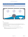
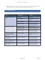
Innovation in Magnetic Field Measuring Instruments
Operation Manual for
PSU1 Power Supply Unit
www.bartington.com
BARTINGTON INSTRUMENTS
Table of Contents
1. Legal Notices
4
1.1. Copyright
4
1.2. Trademarks
4
2. How to Use this Manual
4
2.1. Symbols Glossary
4
2.2. Technical Specifications
4
3. Safe Use
5
4. Applicability 5
5. Compatible Magnetometers 5
6. Introduction to the PSU1 5
6.1 Summary 5
6.2. Functional Description 6
6.2.1. Power 6
6.2.2. Signal Buffering 6
6.2.3. Filtering 6
7. PSU1 Inputs, Outputs and Controls 7
7.1. Back Panel Connections and Controls 7
7.2. Front Panel Controls 8
8. Installing the PSU1 9
8.1. Installing and Replacing the Internal Batteries 9
8.2. Initial Charging of the Battery Cells 13
8.3. Location of the Equipment 13
8.3.1. Potentially Hazardous Locations 13
8.3.2. Orientation 13
8.3.3. Temperature 13
8.3.4. Proximity to Other Equipment 13
8.4. Connecting the Equipment 14
Page 2 of 18OM2443/2
BARTINGTON INSTRUMENTS
8.5. Initial Settings 14
8.5.1. Magnetometer Output Type Selection 9. Using the PSU1 14
14
9.1. Environmental Precautions 14
9.2. Switching On and Off 14
10. Troubleshooting 15
11. Care and Maintenance 16
11.1. Fuses 17
11.2. Calibration 17
11.3. Cleaning 17
12. End of Life Disposal 17
12.1. Waste Electrical and Electronic Equipment (WEEE) Regulations 17
Page 3 of 18OM2443/2
BARTINGTON INSTRUMENTS
1. Legal Notices
1.1. Copyright
The copyright of this document is the property of Bartington Instruments Ltd.
1.2. Trademarks
Bartington® is a trademark in Australia, Canada, China, the European Community, India, Japan,
the countries of the Madrid Agreement & Protocol, Norway and the United States of America.
2. How to Use this Manual
This manual provides the information necessary to help customers install and operate the PSU1
Power Supply Unit from Bartington Instruments.
Photographs of key components are included, labelled with numbers. A number in the text in
square brackets [ ] refers to that label on the nearest photograph above it.
Bartington Instruments cannot advise on the integration of this equipment with any third party
products.
2.1. Symbols Glossary
The following symbols used within this manual call your attention to specific types of
information:
WARNING: Indicates a situation in which serious bodily injury or death could result if the
warning is ignored.
Caution: Indicates a situation in which bodily injury or damage to your instrument, or both,
could result if the caution is ignored.
Identifies items that must be disposed of safely to prevent unnecessary damage to the
environment.
Note: Provides useful supporting information on how to make better use of your purchase.
2.2. Technical Specifications
Technical Specifications for this product can be found in the appropriate datasheets available on
the Bartington Instruments website at www.bartington.com/psu1-power-supply-unit.html.
Page 4 of 18OM2443/2
BARTINGTON INSTRUMENTS
3. Safe Use
WARNING: The PSU1 is fitted with AA size NiMH (Nickel Metal Hydride) rechargeable
batteries. Only AA size rechargeable batteries, which are specified as compatible in the
relevant datasheet, can be used in this product.
WARNING: The fitting of non-approved battery cells may be dangerous and could affect the
safety of users, damage the equipment and also invalidate the terms and conditions of the
Warranty.
WARNING: The PSU1 can also be powered by mains electricity and contains uninsulated
parts. Ensure that the unit is properly earthed at all times. Only properly trained personnel
should open the unit.
WARNING: These products are not qualified for use in explosive atmospheres or life
support systems. Consult Bartington Instruments for advice.
4. Applicability
Caution: This manual applies only to the PSU1 Power Supply Unit. For the earlier
Mag-03PSU, please use the manual supplied with that unit or contact the Bartington
Instruments helpdesk.
5. Compatible Magnetometers
Caution: Use of incompatible magnetometers may cause damage to the PSU1 and/or the
magnetometer. The PSU1 is designed to operate with various Bartington Instruments
magnetometers. For the current list, refer to the datasheet.
6. Introduction to the PSU1
6.1 Summary
The PSU1 provides a battery backed power supply of ±12V for the Mag-03 series of three-axis
fluxgate magnetic field sensors. It also contains filters for the analogue outputs of the sensor.
Page 5 of 18OM2443/2
BARTINGTON INSTRUMENTS
6.2. Functional Description
6.2.1. Power
The PSU1 will supply ±12V DC for powering a range of magnetometers. Please refer to the
datasheet for the latest list of compatible products. The power is supplied from the internal,
rechargeable batteries or from the plug-in power adapter, which is also used to charge the PSU1
batteries.
Note: The PSU1 will operate without any battery cells being installed. To install, or replace
defective cells, refer to section 8.1: Installing and Replacing the Internal Batteries.
6.2.2. Signal Buffering
Single-ended output signals on BNC connectors are buffered from differential or single-ended
output magnetometers.
After filtering, each analogue signal is fed to the appropriate BNC connector via a low impedance
buffer. These buffers allow long cables and low input impedance data acquisition systems to be
used. Refer to the appropriate datasheet for maximum loads.
The output common return is also buffered to eliminate crosstalk due to signal currents sharing
the Va common return. A high impedance AC path is also provided between the Va common and
cable screen to improve AC noise performance.
6.2.3. Filtering
Filtering is provided by a low-pass filter and selectable high-pass filter for DC or AC coupling.
A low pass and a high pass filter are included in each of the channels for the signals from the X,
Y and Z axes of the sensor. Refer to the appropriate datasheet for the frequency response of the
filters.
The low pass filters remove the high frequency noise components of the signal from the sensor.
The high pass filters are intended to isolate the DC or static field component so that the
alternating components above this frequency can be measured or analysed.
Page 6 of 18OM2443/2
BARTINGTON INSTRUMENTS
7. PSU1 Inputs, Outputs and Controls
7.1. Back Panel Connections and Controls
1
2
3
5
4
Key
1. X Signal Conditioned Output.
2. Y Signal Conditioned Output.
3. Z Signal Conditioned Output. The three BNC connectors carry the conditioned analogueue output voltages. The
conditioned outputs are the magnetometer X, Y and Z signals after they have been modified by the low/high pass filters
and, if a balanced output magnetometer is connected, converted to single-sided signals..
4. Space for unique serial number.
5. Magnetometer Socket. This multi-pin socket is for the connection of the magnetometer cable.
Note: Ensure correct orientation of the connector (indicated by the cut-out on the
connector body aligning with the notch in the socket).
Page 7 of 18OM2443/2
BARTINGTON INSTRUMENTS
7.2. Front Panel Controls
6
7
8
9
11
10
Key
6. Magnetometer Output Type Selector Switch
Balanced (out)
Unbalanced (in)
Caution: This switch must be set to match your magnetometer output type to ensure
correct results (see Section 8.5.1: Magnetometer output type selection)
7. DC/AC Coupling (High Pass Filter (HPF) Control)
DC (out)
AC (in)
8. Charge LED
9. ON / OFF LED
10. On/Off Switch
11. Socket for external charging adapter
Page 8 of 18OM2443/2
BARTINGTON INSTRUMENTS
8. Installing the PSU1
8.1. Installing and Replacing the Internal Batteries
To install the battery cells, use the following procedure.
A
C
B
Key
A. Enclosure lid retaining screw.
B. Enclosure lid retaining screw.
C. Earth lead fixing (do not remove)
1. Place the PSU1 on a suitable surface with the underside facing up and the two enclosure lid
retaining screws nearest to you.
Page 9 of 18OM2443/2
BARTINGTON INSTRUMENTS
2. Using a flat-bladed screwdriver of the appropriate size, fully loosen screw [A] to allow the
edge of the lid to clear the enclosure end cap.
3. Fully loosen screw B and the lid of the enclosure will lift due to the internal springs.
Page 10 of 18OM2443/2
BARTINGTON INSTRUMENTS
4. Lift the lid and place aside to gain access to the battery cell compartment.
5. Insert each cell into the compartment in turn. Always fit the negative end of the cell first.
Press the cell back against spring pressure until the positive terminal can be located in the
holder.
Page 11 of 18OM2443/2
BARTINGTON INSTRUMENTS
6. When all five cells are in place, locate the back edge of the lid in the enclosure.
7. Tighten screws [A] and [B] in any order.
8. To remove discharged or defective cells follow the above procedure.
Page 12 of 18OM2443/2
BARTINGTON INSTRUMENTS
8.2. Initial Charging of the Battery Cells
To charge the PSU1 battery, connect the mains charger and switch on the mains supply. The
charging LED [8] will begin to flash, indicating that “fast charging” is taking place. Once the fast
charge cycle has completed, the LED will stop flashing and be lit (ON) continuously to indicate
“trickle charging” is ongoing.
Note: When battery cells are inserted for the first time, they should be continuously
charged for 16 hours to ensure full capacity.
Note: The PSU1 can be used whilst charging the battery cells or directly from mains power
without any battery cells being installed. However the outputs may carry some charger
noise.
Note: If the PSU1 is powered by the mains charger with no batteries cells installed then the
charging LED may flash. This is normal and can be ignored.
Note: To prepare for long periods away from a charging source, battery cells may be precharged and used to replace discharged cells in the field.
8.3. Location of the Equipment
8.3.1. Potentially Hazardous Locations
WARNING: The charger supplied with this equipment is powered by mains electricity. It
should not be used in wet or damp locations, where water may enter the unit and create a
safety hazard.
8.3.2. Orientation
The PSU1 can be orientated horizontally or vertically.
8.3.3. Temperature
To minimise temperature induced drift effects, position the PSU1:
• in a constant ambient temperature
• out of direct sunlight.
8.3.4. Proximity to Other Equipment
The PSU1 contains no high frequency electronics likely to cause emissions which could cause
interference with other equipment. The unit is unlikely to be affected by interference from other
equipment in the normal operating environment.
Page 13 of 18OM2443/2
BARTINGTON INSTRUMENTS
Note: The PSU1 is inherently magnetic and should, therefore, be sited as far from any
magnetometers as possible.
8.4. Connecting the Equipment
Caution: Connection between the magnetometer and the power supply should not be
made or broken with the power supply switched on as this could cause damage to the
magnetometer.
Connect the equipment in the following sequence:
1. Ensure the ON/OFF switch [10] is OFF (position “0”).
2. Connect the magnetometer to the PSU1 magnetometer socket. Ensure the connector pins
are correctly aligned with those in the socket. The locking ring should be hand-tightened
only.
3. Connect BNC outputs to your external equipment, as required.
8.5. Initial Settings
8.5.1. Magnetometer Output Type Selection
Before switching on the equipment, set the magnetometer output type selector switch to the
correct position for your magnetometer. Refer to the appropriate magnetometer datasheets.
9. Using the PSU1
9.1. Environmental Precautions
Refer to the Mag-03 datasheet at www.bartington.com/Literaturepdf/Datasheets/Mag-03%20
DS0013.pdf for maximum environmental, electrical and mechanical ratings for the PSU1.
Caution: Exceeding the maximum environmental ratings may cause irreparable damage to
the equipment.
9.2. Switching On and Off
Caution: Connect the magnetometer before switching on the PSU1, as connecting a live
cable to the magnetometer may cause damage. Similarly, switch off the PSU1 before
disconnecting the magnetometer.
With the ON/OFF switch [10] ON (position “1”), the ON/OFF LED [9] will be continuously lit (ON).
Page 14 of 18OM2443/2
BARTINGTON INSTRUMENTS
Note: For best results, after switching on the power, leave the PSU1 for 20 minutes for the
internal temperature to stabilise, before performing any measurements.
10. Troubleshooting
If the PSU1 exhibits unexpected behaviour, please check possible causes in the following table:
Fault
Possible Cause
Solution
No power output from the
PSU1
Battery flat
Recharge
Battery expired
Replace batteries and
charge
Battery not fitted
Fit batteries and charge
None of the above
Return to Bartington
Instruments for repair
Failed 12V charger
Replace charger
Battery not fitted
Fit batteries and charge
None of the above
Return to Bartington
Instruments for repair
PSU1 does not hold its
charge (reduced battery
operation)
Batteries expired
Replace batteries and
charge
PSU1 stuck in AC or DC
coupling mode
Defective component
Return to Bartington
Instruments for repair
PSU1 stuck in Balanced or
Unbalanced mode
Defective component
Return to Bartington
Instruments for repair
One or both LEDs do not
light correctly
Defective component
Return to Bartington
Instruments for repair
PSU1 does not charge
Page 15 of 18OM2443/2
BARTINGTON INSTRUMENTS
With a sensor connected, all
output signals are faulty
With a sensor connected,
one or two output signals
are faulty
Coupled incorrectly
Check position of AC/DC
coupling switch
Balance mode set
incorrectly
Check position of balanced/
unbalanced mode switch
Defective sensor cable
Check sensor cable using
relevant datasheet. Return
to Bartington Instruments if
found to be defective
Sensor defective
Return PSU1 and sensor to
Bartington Instruments for
repair
PSU1 defective
Return PSU1 and sensor to
Bartington Instruments for
repair
Defective sensor cable
Check sensor cable using
relevant datasheet. Return
to Bartington Instruments if
found to be defective
Sensor defective
Return PSU1 and sensor to
Bartington Instruments for
repair
PSU1 defective
Return PSU1 and sensor to
Bartington Instruments for
repair
If the solutions suggested above do not fix the fault, contact the Bartington Instruments
helpdesk.
11. Care and Maintenance
The PSU1 requires no routine maintenance. There are no user serviceable parts.
Caution: No attempt should be made by a user to repair the unit. Repairs by unauthorised
people may be dangerous and could affect the safety of users, damage the equipment, and
also invalidate the terms and conditions of the Warranty.
Page 16 of 18OM2443/2
BARTINGTON INSTRUMENTS
11.1. Fuses
As a safety feature the PSU1 is fitted with a thermal fuse. If the PSU1 overheats, which could
occur as a result of the fitment of incorrect battery cells, the charging circuit will be permanently
isolated. The PSU1 must be returned to Bartington Instruments for checks and repair.
11.2. Calibration
No calibration is required.
11.3. Cleaning
Caution: Disconnect the electrical supply before performing any cleaning operation.
Periodic cleaning is not normally required.
If the system becomes soiled and cleaning is necessary:
1. Use a damp cloth to clean the outer surfaces.
2. Use an air duster to blow debris from the connectors.
Caution: Ensure water does not enter the system. The system must be completely dry
before the electrical supply is reconnected.
Caution: Never use chemicals, such as solvents, when cleaning the PSU1.
Caution: Take particular care when cleaning around electrical connections. Bent or
damaged pins may cause the magnetometer to malfunction.
12. End of Life Disposal
This product should not be disposed of in domestic or municipal waste. For information about
disposing of this product safely, check local regulations for disposal of electrical / electronic
products.
12.1. Waste Electrical and Electronic Equipment (WEEE) Regulations
This product complies fully with Restriction of the Use of Certain Hazardous Substances in
Electrical and Electronic Equipment (RoHS) and WEEE Regulations current at the time of
writing.
Page 17 of 18OM2443/2
OM2443/2
Bartington Instruments Limited
T: +44 (0)1993 706565
5, 10 & 11 Thorney Leys Business Park
F: +44 (0)1993 774813
Witney, Oxford, OX28 4GE, England
E:[email protected]
The specifications of the products described in this brochure
are subject to change without prior notice. Bartington® is a
registered trademark of Bartington Instruments Ltd.
www.bartington.com