1
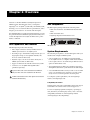
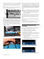
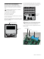
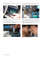
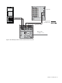
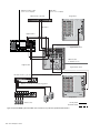
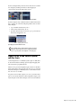
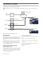
HDx TDM Record/Playback Option For VENUE Systems Digidesign 2001 Junipero Serra Boulevard Daly City, CA 94014-3886 USA Technical Support (USA) Visit the Digidesign Online Support Center at www.digidesign.com/support Product Information For company and product information, visit us on the web at www.digidesign.com Guide Part Number 9321-62341-00 REV A 10/09 Legal Notices Communication Statement This guide is copyrighted ©2009 by Avid Technology, Inc., with all rights reserved. Under copyright laws, this guide may not be duplicated in whole or in part without the written consent of Avid Technology, Inc. NOTE: This equipment has been tested and found to comply with the limits for a Class B digital device, pursuant to Part 15 of the FCC Rules. These limits are designed to provide reasonable protection against harmful interference in a residential installation. This equipment generates, uses, and can radiate radio frequency energy and, if not installed and used in accordance with the instructions, may cause harmful interference to radio communications. However, there is no guarantee that interference will not occur in a particular installation. If this equipment does cause harmful interference to radio or television reception, which can be determined by turning the equipment off and on, the user is encouraged to try and correct the interference by one or more of the following measures: • Reorient or locate the receiving antenna. • Increase the separation between the equipment and receiver. • Connect the equipment into an outlet on a circuit different from that to which the receiver is connected. • Consult the dealer or an experienced radio/TV technician for help. 003, 96 I/O, 96i I/O, 192 Digital I/O, 192 I/O, 888|24 I/O, 882|20 I/O, 1622 I/O, 24-Bit ADAT Bridge I/O, AudioSuite, Avid, Avid DNA, Avid Mojo, Avid Unity, Avid Unity ISIS, Avid Xpress, AVoption, Axiom, Beat Detective, Bomb Factory, Bruno, C|24, Command|8, Control|24, D-Command, D-Control, D-Fi, D-fx, D-Show, D-Verb, DAE, Digi 002, DigiBase, DigiDelivery, Digidesign, Digidesign Audio Engine, Digidesign Intelligent Noise Reduction, Digidesign TDM Bus, DigiDrive, DigiRack, DigiTest, DigiTranslator, DINR, D-Show, DV Toolkit, EditPack, Eleven, HD Core, HD Process, Hybrid, Impact, Interplay, LoFi, M-Audio, MachineControl, Maxim, Mbox, MediaComposer, MIDI I/O, MIX, MultiShell, Nitris, OMF, OMF Interchange, PRE, ProControl, Pro Tools M-Powered, Pro Tools, Pro Tools|HD, Pro Tools LE, QuickPunch, Recti-Fi, Reel Tape, Reso, Reverb One, ReVibe, RTAS, Sibelius, Smack!, SoundReplacer, Sound Designer II, Strike, Structure, SYNC HD, SYNC I/O, Synchronic, TL Aggro, TL AutoPan, TL Drum Rehab, TL Everyphase, TL Fauxlder, TL In Tune, TL MasterMeter, TL Metro, TL Space, TL Utilities, Transfuser, Trillium Lane Labs, Vari-Fi Velvet, X-Form, and XMON are trademarks or registered trademarks of Digidesign and/or Avid Technology, Inc. Xpand! is Registered in the U.S. Patent and Trademark Office. All other trademarks are the property of their respective owners. Product features, specifications, system requirements, and availability are subject to change without notice. Any modifications to the unit, unless expressly approved by Digidesign, could void the user's authority to operate the equipment. Canadian Compliance Statement: This Class B digital apparatus complies with Canadian ICES-003. Cet appareil numérique de la classe B est conforme à la norme NMB-003 du Canada. Australian Compliance Guide Part Number 9321-62341-00 REV A 10/09 Documentation Feedback At Digidesign, we are always looking for ways to improve our documentation. If you have comments, corrections, or suggestions regarding our documentation, email us at [email protected]. Communications and Safety Regulation Information Compliance Statement This model Digidesign HDx TDM Option complies with the following standards regulating interference and EMC: • FCC Part 15 Class B • EN 55103-1 E3 • EN 55103-2 E3 • AS/NZS 3548 Class B • CISPR 22 Class B Radio and Television Interference This equipment has been tested and found to comply with the limits for a Class B digital device, pursuant to Part 15 of the FCC Rules. DECLARATION OF CONFORMITY We Digidesign, 2001 Junipero Serra Boulevard, Suite 200 Daly City, CA 94014 USA tel: 650-731-6300 declare under our sole responsibility that the product HDx TDM Option complies with Part 15 of FCC Rules. Operation is subject to the following two conditions: (1) this device may not cause harmful interference, and (2) this device must accept any interference received, including interference that may cause undesired operation. European Compliance Contents Chapter 1. Overview . . . . . . . . . . . . . . . . . . . . . . . . . . . . . . . . . . . . . . . . . . . . . . . . . . . . . . . . . . . . . . . . . . . . . . . . . . . . . . 1 HDx Capabilities and Features . . . . . . . . . . . . . . . . . . . . . . . . . . . . . . . . . . . . . . . . . . . . . . . . . . . . . . . . . . . . . . . . . . . . 1 HDx Components . . . . . . . . . . . . . . . . . . . . . . . . . . . . . . . . . . . . . . . . . . . . . . . . . . . . . . . . . . . . . . . . . . . . . . . . . . . . . 1 System Requirements . . . . . . . . . . . . . . . . . . . . . . . . . . . . . . . . . . . . . . . . . . . . . . . . . . . . . . . . . . . . . . . . . . . . . . . . . . 1 Conventions Used in This Guide . . . . . . . . . . . . . . . . . . . . . . . . . . . . . . . . . . . . . . . . . . . . . . . . . . . . . . . . . . . . . . . . . . . 2 Chapter 2. Installing HDx . . . . . . . . . . . . . . . . . . . . . . . . . . . . . . . . . . . . . . . . . . . . . . . . . . . . . . . . . . . . . . . . . . . . . . . . . . 3 FOH Rack HDx Card Installation . . . . . . . . . . . . . . . . . . . . . . . . . . . . . . . . . . . . . . . . . . . . . . . . . . . . . . . . . . . . . . . . . . . 3 Confirming FOH Rack HDx Card Installation . . . . . . . . . . . . . . . . . . . . . . . . . . . . . . . . . . . . . . . . . . . . . . . . . . . . . . . . . . . 4 Mix Rack HDx Card Installation. . . . . . . . . . . . . . . . . . . . . . . . . . . . . . . . . . . . . . . . . . . . . . . . . . . . . . . . . . . . . . . . . . . . 5 Confirming Mix Rack HDx Card Installation . . . . . . . . . . . . . . . . . . . . . . . . . . . . . . . . . . . . . . . . . . . . . . . . . . . . . . . . . . . 7 Connecting Pro Tools|HD to HDx . . . . . . . . . . . . . . . . . . . . . . . . . . . . . . . . . . . . . . . . . . . . . . . . . . . . . . . . . . . . . . . . . . 8 Power Sequence . . . . . . . . . . . . . . . . . . . . . . . . . . . . . . . . . . . . . . . . . . . . . . . . . . . . . . . . . . . . . . . . . . . . . . . . . . . . . . 8 Chapter 3. Using HDx . . . . . . . . . . . . . . . . . . . . . . . . . . . . . . . . . . . . . . . . . . . . . . . . . . . . . . . . . . . . . . . . . . . . . . . . . . . . 11 Overview . . . . . . . . . . . . . . . . . . . . . . . . . . . . . . . . . . . . . . . . . . . . . . . . . . . . . . . . . . . . . . . . . . . . . . . . . . . . . . . . . . 11 Signal Routing for HDx Recording . . . . . . . . . . . . . . . . . . . . . . . . . . . . . . . . . . . . . . . . . . . . . . . . . . . . . . . . . . . . . . . . . 12 Signal Levels in the VENUE System and Pro Tools. . . . . . . . . . . . . . . . . . . . . . . . . . . . . . . . . . . . . . . . . . . . . . . . . . . . . . 15 Signal Routing for HDx Playback. . . . . . . . . . . . . . . . . . . . . . . . . . . . . . . . . . . . . . . . . . . . . . . . . . . . . . . . . . . . . . . . . . 16 Example Recording and Playback Configurations . . . . . . . . . . . . . . . . . . . . . . . . . . . . . . . . . . . . . . . . . . . . . . . . . . . . . . 19 Managing VENUE Settings During HDx Playback. . . . . . . . . . . . . . . . . . . . . . . . . . . . . . . . . . . . . . . . . . . . . . . . . . . . . . . 20 Using Synchronization and Time Code with HDx . . . . . . . . . . . . . . . . . . . . . . . . . . . . . . . . . . . . . . . . . . . . . . . . . . . . . . . 21 Monitoring HDx Recordings . . . . . . . . . . . . . . . . . . . . . . . . . . . . . . . . . . . . . . . . . . . . . . . . . . . . . . . . . . . . . . . . . . . . . 21 Contents iii iv HDx TDM Option Guide Chapter 1: Overview Welcome to the HDx TDMRecord/Playback Option for VENUE systems. The HDx Option lets you integrate a Digidesign® Pro Tools|HD® system with your VENUE system, allowing you to record and archive live performances, and to integrate pre-recorded Pro Tools tracks with live inputs. By combining HDx’s recording and playback features, you can also perform Virtual Soundchecks: play back the tracks you recorded the night before and adjust the mix before a performance or rehearsal. HDx Capabilities and Features HDx Components The HDx Option package includes the following items: • HDx card (installs into the VENUE FOH Rack and Mix Rack) • HDx card ribbon cable • Digidesign Registration Information card HDx Option card The HDx Option provides the following: • Direct digital connection (24-bit, 48 kHz) between a VENUE system and a Pro Tools|HD system • Recording of up to 128 channels of digital audio (up to 96 Stage inputs and up to 32 assignable channels) into Pro Tools (with two HDx cards) System Requirements The following are required to use the HDx Option with your installed and configured VENUE system: • Support for Windows XP and Mac OS X-based systems • A Pro Tools|HD or Pro Tools|HD Accel system running Pro Tools|HD version 6.9 or higher. An HD Audio Interface is not required. Two Pro Tools HD cards per HDx card are required for full channel count. • Connects to Pro Tools|HD with DigiLink cables (purchased separately) • Two DigiLink cables per HDx card (purchased separately). All DigiLink cables in the system should be the same length. • Playback of up to 128 Pro Tools tracks directly into a VENUE system (with two HDx cards) Up to two HDx cards can be installed in the FOH Rack. Only one HDx card can be installed in the Mix Rack. • A second FOH Rack Snake card if you want to use two HDx cards. A second Snake card is required to provide system clock, even if a second Stage Rack is not being used. An HDx card and an FWx FireWire Option Card cannot be installed simultaneously. For complete system requirements, visit the Digidesign website (www.digidesign.com). Compatibility Information Digidesign can only assure compatibility and provide support for hardware and software it has tested and approved. For a list of Digidesign-qualified computers, operating systems, hard drives, and third-party devices, refer to the latest compatibility information on the Digidesign website (www.digidesign.com/compatibility). Chapter 1: Overview 1 Conventions Used in This Guide Our guides use the following conventions to indicate menu choices and key commands: Convention Action File > Save Choose Save from the File menu Control+N Hold down the Control key and press the N key Control-click Hold down the Control key and click the mouse button Right-click Click with the right mouse button The names of Commands, Options, and Settings that appear on-screen are in a different font. The following symbols are used to highlight important information: User Tips are helpful hints for getting the most from your VENUE system. Important Notices include information that could affect your data or the performance of your system. Shortcuts show you useful keyboard or mouse shortcuts. Cross References point to related sections in this guide and other guides. 2 HDx TDM Option Guide Chapter 2: Installing HDx f you are using an FOH Rack with your VENUE system, see “FOH Rack HDx Card Installation” on page 3. If you are using a Mix Rack, see “Mix Rack HDx Card Installation” on page 5. 6 On the back panel of the FOH Rack, remove the faceplate on any available expansion slot by removing the screws holding it in place. Keep the screws nearby for securing the HDx card to the FOH Rack later. FOH Rack HDx Card Installation This section shows how to install an HDx card in an FOH Rack. A maximum of two HDx cards can be installed in an FOH Rack. Expansion slot faceplate (remove) To install an HDx card in an FOH Rack: 1 Shut down your sound system. 2 Power down the FOH Rack. 3 Disconnect power, audio, FOH Link, and any other cables attached to the FOH Rack. 4 Remove the front panel faceplate by unscrewing its mount- ing screws (#1 Phillips). Keep the screws nearby for remounting the front panel later. Mounting screws (remove all) Back panel of the FOH Rack 7 Remove the HDx card from its packing material. Hold the card by its edges. Mounting bracket Power connector Ribbon Cable connector Faceplate Front panel of the FOH Rack 5 If your system has an FWx FireWire Option card installed, disconnect its ribbon cable and remove the card. HDx and FWx (FireWire Record/Playback Option) cards cannot be installed in the FOH Rack simultaneously. HDx card showing bracket and connectors 8 Gently slide the card into the expansion slot. Make sure it is oriented right-side up. Chapter 2: Installing HDx 3 9 When the card is seated in its slot, secure it to the FOH chas- 12 If you are connecting a second HDx card, attach its ribbon sis with the mounting screw at the end of the HDx mounting bracket (accessible from the open front panel of the FOH Rack). cable from the ribbon connector on the HDx card to the connector labeled “FireWire” on the second Mix Engine card from the back. The HDx card connected to this second Mix Engine card will appear as HDx2 in on-screen. Make sure the pins are oriented correctly, and that each connector is attached securely. 10 Secure the HDx card to the back panel of the FOH Rack us- ing the two screws that held the faceplate. HDx card A single installed HDx card may be connected to the second Mix Engine card, which will then appear on the system as HDx2. A second FOH Rack Snake card is required to use any HDx card as HDx2. 13 Attach an available power cable plug to the power socket on each HDx card. Make sure they are connected securely. 14 Reattach the FOH Rack front panel faceplate using its Installing the HDx card to the back panel of the FOH Rack 11 Attach the included ribbon cable to the ribbon connector on the HDx card and to the connector labeled “FireWire” on the first Mix Engine card (the rear-most card when viewed from the open front panel). Make sure the pins are oriented correctly, and that each connector is attached securely. The HDx card connected to this first Mix Engine card will appear as HDx1 in on-screen. screws. 15 Reconnect power, audio, FOH Link, and any MIDI cables to the FOH Rack. 16 Power on all VENUE system components. Proceed to “Confirming FOH Rack HDx Card Installation” on page 4. Confirming FOH Rack HDx Card Installation After you have installed the HDx card in your FOH Rack, you can confirm that you have installed it properly. To confirm HDx card installation, do the following: 1 Go to the Options > Devices page. 2 Confirm the HDx card’s presence in your FOH Rack. When successfully installed, the HDx card is detected and shown on-screen in the following ways: Attaching the ribbon cable to the HDx card • The HDx card connected to the rear-most Mix Engine card appears as HDx1. • The HDx card connected to the second Mix Engine card from the back appears as HDx2. HDx card indicated in the FOH Rack icon in the Devices page Attaching the ribbon cable to the Mix Engine card Two HDx cards indicated in the FOH Rack icon in the Devices page 4 HDx TDM Option Guide Mix Rack HDx Card Installation This section shows how to install an HDx card into a Mix Rack. One HDx card can be installed in a Mix Rack, and the FWx card and the HDx card cannot be used simultaneously. 5 On the Mix Rack’s back panel, remove the top expansion slot cover by unscrewing its mounting screws. Keep the screws nearby in order to secure the HDx card to the Mix Rack. For FOH Rack installation instructions, see “FOH Rack HDx Card Installation” on page 3. To install the HDx card in the Mix Rack: 1 Shut down your sound system. Top expansion slot cover (remove) 2 Power down your Mix Rack. 3 Disconnect all power, audio, FOH Link, and any other cables attached to the Mix Rack. 4 Remove the front panel faceplate by unscrewing its mounting screws (#1 Phillips). Keep the screws nearby for remounting the front panel later. Back of the Mix Rack Although there are two expansion slots in which you can install the HDx card, for ease of installation it is suggested that you install the card in the top expansion slot. Mounting screws (remove all) 6 Remove the HDx card from its packing material. Hold the card by its edges. Mounting bracket Faceplate Power connector Ribbon Cable connector Front of the Mix Rack HDx card showing bracket and connectors Chapter 2: Installing HDx 5 7 Gently slide the card into the expansion slot. Make sure it is oriented right-side up. 10 Cut the zip tie that secures the expansion card power cable to the chassis, being careful not to cut the wires. Installing the HDx card in the back of the Mix Rack Cutting the expansion card power cable zip tie 8 Secure the HDx to the back of the Mix Rack using the screws that secured the expansion slot cover. 11 Attach an available internal power cable plug to the power 9 Inside the Mix Rack, secure the HDx card to the Mix Rack’s chassis by tightening the captive thumbscrews. Securing the HDx card to the Mix Rack’s chassis 6 HDx TDM Option Guide socket on the HDx card by holding the socket on the HDx and pushing the plug firmly into the socket. When the power cable plug is correctly attached to the HDx card, the yellow wire should be the first wire from the left. Attaching an internal power cable plug 12 Attach the included ribbon cable to the ribbon connector socket labelled “FireWire” on the first Mix Engine card (the rear most card when viewed from the open front panel). Make sure that the ribbon cable connector’s notch is facing you when attaching the cable. Confirming Mix Rack HDx Card Installation After you have installed the HDx card in your Mix Rack, you should confirm that you have successfully installed it. To confirm HDx card installation, do the following: 1 Go to the Options > Devices page. 2 Confirm the HDx card’s presence in your Mix Rack. When successfully installed, the HDx card is detected and shown on-screen. If the HDx card graphic is not displayed, power down the system and check all cables and connections. Attaching ribbon cable connector to rear most DSP Mix Engine card 13 Attach the other end of the ribbon cable to the ribbon connector socket on the HDx card. Make sure that the ribbon cable’s notch is facing upwards when attaching the cable. A correctly attached ribbon cable and power cable 14 Reattach the Mix Rack faceplate using its screws. HDx Detail of Devices tab indicating presence of an HDx card in the expansion card slot 15 Reconnect power, audio, FOH Link, and any other cables to the FOH Rack. 16 Power on all system components. Proceed to “Confirming Mix Rack HDx Card Installation” on page 7. Chapter 2: Installing HDx 7 Connecting Pro Tools|HD to HDx Pro Tools with HDx supports up to two HDx cards, each with two 32-channel DigiLink connectors, for a total of 128 channels of input or output to your VENUE system. Each HDx port is connected with a DigiLink cable (available separately from Digidesign) to an HD Core, Process, or Accel card in the Pro Tools computer or Expansion Chassis. All DigiLink cables connecting the HDx cards to the Pro Tools|HD cards must be the same length. Connecting Pro Tools HD Cards to HDx The HDx card ports can be connected to the Pro Tools HD cards in any sequence, but if you are connecting an HD-series audio interface to the system, it must be connected to the last Pro Tools|HD card in the sequence (the HD card farthest away from the HD Core card). Basic System The following is an example connection scheme for a single HDx card and Pro Tools system with an HD Core card and one additional card. See Figure 1 on page 9 for an example system diagram. 1 Pro Tools HD Core card: HDx1 card port A Using an HD Audio Interface with HDx (Optional) You can connect one HD audio interface (192 I/O, 192 Digital I/O, 96 I/O, or 96i I/O) to the Pro Tools system to allow remote monitoring of audio by the recording engineer, or remote audio input to the Pro Tool system, such as with audience microphones in live performance. Word Clock Connections If a Pro Tools HD audio interface (192 I/O, 192 Digital I/O, 96 I/O, or 96i I/O) is connected to the system, a Word Clock connection between the VENUE system and the audio interface is required. If no Pro Tools HD audio interface is used, a Word Clock connection is not needed. To connect Word Clock between the VENUE system and a Pro Tools|HD peripheral: 1 Connect one end of a BNC cable to the Word Clock Out port on the FOH Rack. (If a second FOH Snake card is present in the FOH Rack, connect the cable to the Word Clock Out port on the second FOH Snake card.) 2 Connect the other end of the BNC cable to the Loop Sync in port on the HD audio interface. 2 Pro Tools HD Process or Accel card #1: HDx1 card port B Power Sequence Expanded System The following is an example connection scheme for two HDx cards and a Pro Tools system with an HD Core and 4 additional cards. See Figure 2 on page 10 for an example system diagram. 1 Pro Tools HD Core card: HDx1 card port A. 2 Pro Tools HD Process or Accel card #1: HDx1 card port B. 3 Pro Tools HD Process or Accel card #2: HDx2 card port A. 4 Pro Tools HD Process or Accel card #3: HDx2 card port B. 5 Pro Tools HD Process or Accel card #4: HD audio interface. Whenever you are using a Pro Tools system with HDx, always power up the system in the following sequence. Power up the VENUE system and the Pro Tools system in the following order: 1 Power up VENUE system components in the following or- der: • Main Unit and Sidecars, or Profile • Mix Rack, or Stage Racks and FOH Rack. 2 Start up the Pro Tools computer. 3 Launch Pro Tools. Power down the VENUE system and the Pro Tools system in the following order: 1 Quit Pro Tools. 2 Shut down the Pro Tools computer. 3 Shut down the VENUE system in the following order: • Mix Rack, or FOH Rack and Stage Rack • Main Unit and Sidecars, or Profile 8 HDx TDM Option Guide Stage Rack DigiLink cables Primary Snake Redundant Snake Computer Digital Snake cables FOH Link cable (to VENUE console) FOH Rack Figure 1. Basic VENUE system with one HDx card and 2-card Pro Tools system Chapter 2: Installing HDx 9 Expansion Chassis cable (to Pro Tools computer) USB cable (to Pro Tools computer) MIDI Interface (optional) Stage Rack 1 MIDI cables DigiLink cables Digital Snake cables Expansion Chassis DigiLink cables FOH Link cable (to VENUE console) DigiLink cable Digital Snake cables FOH Rack HD Audio Interface (optional) Word Clock cable Output to remote Pro Tools monitoring system Mic Preamp Stage Rack 2 Audience mics Primary Snake Redundant Snake Figure 2. Expanded VENUE system with 2 HDx cards, 5-card Pro Tools system and optional HD audio interface 10 HDx TDM Option Guide Chapter 3: Using HDx Overview Each HDx card allows up to 64 channels of audio to be recorded into Pro Tools. You can also playback your recorded tracks through your VENUE system so you can, for example, perform a Virtual Soundcheck. Two HDx cards can be installed into an FOH Rack, allowing up to 128 record or playback channels. Signal routing for recording or playback is configured in both the VENUE system and Pro Tools. VENUE System Settings HDx Outputs (Recording) Each HDx card provides 48 fixed outputs and 16 assignable outputs for recording of VENUE system channels into Pro Tools: Pro Tools System Settings HDx outputs and inputs appear in Pro Tools in the same way as Pro Tools|HD audio interface outputs and inputs. Each port on an HDx card carries 32 channels of input and output to Pro Tools, and appears as two interfaces (related groups of 16 channels) in the Pro Tools Hardware Setup dialog, as follows: • HDx1 card Port A appears as HDx1 A1 and HDx1 A2 • HDx1 card Port B appears as HDx1 B1 and HDx1 B2 • HDx2 card Port A appears as HDx2 A1 and HDx2 A2 • HDx2 card Port B appears as HDx2 B1 and HDx2 B2 HDx assignable inputs and outputs correspond to the 16 input and output channels on HDx1 B2. On systems with two HDx cards, assignable inputs and outputs from the second HDx card correspond to the 16 input and output channels on HDx2 B2. Use HDx fixed output channels 1–48 (or 49–96 if using a second Stage Rack and a second HDx card) to record direct digital splits of Mix Rack or Stage Rack inputs 1–48 (or 49–96 if using a second Stage Rack and a second HDx card). Use the Patchbay > Outputs page (or Directs page) to route output busses (or channel Direct Outputs) to HDx assignable output channels 1–16 (or 17–32 if using a second HDx card). HDx card in the Pro Tools Hardware Setup window HDx Inputs (Playback) Each HDx card provides 48 fixed inputs and 16 assignable inputs for playback of Pro Tools tracks through the VENUE system: HDx outputs and inputs appear in the Pro Tools I/O Setup window with similar labels, allowing you to assign Pro Tools track inputs and outputs to HDx. Use the Options > System Configuration page to replace Mix Rack or Stage Rack Inputs 1–48 (or 49–96 if using a second Stage Rack and a second HDx card) with HDx fixed input channels 1–48 (or 49–96 if using a second Stage Rack and a second HDx card). These channels can then be routed to any Input Channel or FX Return in the Patchbay. Use the Patchbay > Inputs page to route HDx assignable input channels 1–16 (or 17–32 if using a second HDx card) to any available your console’s Input Channels or FX Returns. HDx inputs in the Outputs page of the Pro Tools I/O Setup window Chapter 3: Using HDx 11 Signal Routing for HDx Recording Each HDx card provides 48 fixed outputs and 16 assignable outputs for recording VENUE system channels into Pro Tools. The HDx fixed output channels take a direct split from the Stage Rack or the Mix Rack inputs. The input signal is split immediately after the input stage, and these input signals output directly to Pro Tools. The fixed output channels do not appear separately in the Patchbay. Mix Rack inputs are referred to as “Stage” inputs, while Stage Rack inputs are referred to as “Stage 1” and “Stage 2” inputs. Options > System tab Inputs set to “Stage 1” (or “Stage” for Mix Rack) Analog Stage Inputs 1–48 Stage Rack 1 (or Mix Rack) Patchbay “Stage 1” (or “Stage” for Mix Rack) HDx1 A1 To Pro Tools Inputs HDx fixed outputs HDx1 A2 HDx1 B1 HDx1 A1 From Pro Tools Outputs HDx fixed inputs HDx1 A2 HDx1 B1 To and From Pro Tools HDx assignable inputs and outputs Patchbay “Pro Tools” HDx1 B2 Figure 3. HDx signal flow for recording into Pro Tools HDx Fixed Outputs HDx fixed output channels (1–48 with a Stage Rack or a Mix Rack, and 49–96 on systems with two Stage Racks and two HDx cards) mirror the input signal from the corresponding Stage Rack and Mix Rack inputs (1–48, 49–96). Systems with One Stage Rack and One HDx Card (FOH Rack Only) On VENUE systems with one Stage Rack and one HDx card, Stage Rack inputs 1–48 can be selected at any time to enable recording of live input into Pro Tools. 12 HDx TDM Option Guide To select HDx fixed outputs for the first Stage Rack (1–48): 1 Do one of the following to put your system into Config Mode: • Press the Console Config switch on the console – or – • Double-click the Mode box in the bottom-right corner of the screen. 2 Go to the Options page and click the System tab to access the System Configuration page. 3 Click Edit. 4 In the Inputs section of the System Config page, next to Inputs 1–48, select Stage 1. Selecting Fixed Outputs for the Second Stage Rack When Stage Rack Inputs 49–96 are made available, they can then be selected to enable recording of live input from the corresponding channels into Pro Tools. To select HDx fixed outputs for the second Stage Rack (49–96): 1 Do one of the following to put your system into Config Selecting Stage 1 inputs Mode: 5 Click Apply. The system restarts with the Stage 1 inputs active. • Press the Console Config switch on the console Inputs 1–48 on the first HDx card appear in the Inputs page of the Pro Tools I/O Setup dialog as Inputs “HDx1 1–48.” • Double-click the Mode box in the bottom-right corner of the screen. HDx outputs 1–48 are always active and available within Pro Tools when Stage Inputs 1–48 are selected. Systems with Two Stage Racks and Two HDx Cards (FOH Rack Only) – or – 2 Go to the Options page and click the System tab to access the System Configuration page. 3 Click Edit. 4 In the Inputs section of the System Configuration page, next to Inputs 49–96, select Stage 2. Enabling the Second Stage Rack and HDX Card On VENUE systems with two Stage Racks and two HDx cards, the second Stage Rack and the second HDx card must first be enabled to make Stage Rack Inputs 49–96 available in the Inputs page of the Pro Tools I/O Setup dialog. This is typically done once when you are setting up the system. Selecting Stage 2 inputs To enable the second Stage Rack and HDx card: 1 Do one of the following to put your system into Config Mode: • Press the Console Config switch on the console 5 Click Apply. The system restarts with the Stage 2 inputs active. Inputs 1–48 on the second Stage Rack appear in the Inputs page of the Pro Tools I/O Setup dialog as Inputs “HDx2 1–48.” – or – • Double-click the Mode box in the bottom-right corner of the screen. 2 Go to the Options page and click the System tab to access Systems with a Mix Rack and an HDx Card (Mix Rack Only) 3 Click Edit. On VENUE systems using a Mix Rack and an HDx card, Mix Rack inputs 1-48 can be selected at any time to enable recording of live input into Pro Tools. 4 Select Enable Stage 2. To select HDx fixed outputs for Mix Rack (1-48): 5 Select Enable HDx2. 1 Do one of the following to put your system into Config the System Configuration page. Mode: • Press the Console Config switch on the console – or – • Double-click the Mode box in the bottom-right corner of the screen. 2 Go to the Options page and click the System tab to access Enabling the second Stage Rack and HDx card the System Configuration page. 6 Click Apply. The system restarts with the second Stage Rack and HDx card enabled. 3 Click Edit. Chapter 3: Using HDx 13 4 In the Inputs section of the System Configuration page, 2 Go to the Options page and click the System tab to access next to Inputs 1–48, select Stage. the System Configuration page. 3 Click Edit. 4 Select Enable HDx2. Selecting Stage inputs 5 Click Apply. The system restarts with the Stage inputs active. Inputs 1–48 on the first HDx card appear in the Inputs page of the Pro Tools I/O Setup dialog as Inputs “HDx1 1–48.” HDx outputs 1–48 are always active and available within Pro Tools when Stage Inputs 1–48 are selected. HDx Assignable Outputs HDx assignable output channels (HDx1 assignable 1–16, and HDx2 Assignable 1–16 on systems with two HDx cards) can receive signal from any mono or stereo VENUE system channel, including channel Direct Outputs, Auxes, mono or stereo Groups, Matrix outputs, PQ outputs, or Mains. HDx assignable outputs can be configured and routed independently from HDx fixed outputs. Enabling the second HDx card 5 Click Apply. The system restarts with the second HDx card enabled. HDx assignable outputs on the second HDx card appear in the Inputs page of the Pro Tools I/O Setup dialog as Inputs “HDx2 Assignable 1–16.” Routing Assignable HDx Outputs With HDx assignable outputs available in Pro Tools, you can route any mono or stereo VENUE system channel to HDx assignable outputs, including channel Direct Outputs, Mains, Auxes, mono or stereo Groups, Matrix outputs, and PQ outputs. Enabling Assignable Outputs on Systems with One HDx Card Using Direct Outputs lets you record discrete channels from the pickoff point you choose. On VENUE systems with one HDx card, HDx assignable outputs are automatically available in the Inputs page of the Pro Tools I/O Setup dialog as Inputs “HDx1 Assignable 1–16.” Using Mains, Aux, Group, Matrix, or PQ outputs lets you record a stereo main mix, one or more stereo submixes, or any combination of these, up to the number of available HDx assignable outputs. Enabling Assignable Outputs on Systems with Two HDx Cards To route a VENUE system channel to an HDx assignable output: 1 Go to the Patchbay page and do one of the following: On VENUE systems with two HDx cards, to make the assignable outputs on the second HDx card available in the Inputs page of the Pro Tools I/O Setup dialog, the card must first be enabled in the D-Show software. This is typically done once when you are setting up the system. A second Snake card in the FOH Rack is required to use a second HDx card, but a second Stage Rack does not need to be present or enabled for the HDx2 card to be enabled. To enable the second HDx card: 1 Do one of the following to put your system into Config Mode: • Press the Console Config switch on the console – or – • Double-click the Mode box in the bottom-right corner of the screen. 14 HDx TDM Option Guide • Click the Outputs tab, and click the Mains, PQ, Matrix, Aux or Group tab to the left of the channel grid. – or – • Click the Directs tab, and click the Channels, FX Returns, or Outputs tab to the left of the channel grid. 2 Click the Pro Tools tab at the top right of the channel grid to show the available HDx assignable outputs. 3 Click in the channel grid to route a VENUE channel (listed on the left) to an available HDx assignable output (listed across the top). 4 (Direct Outputs Only) Activate and set the level for each Di- rect Output by clicking its In button and dragging its on-screen encoder in the Direct Out section. Activating a Direct Output in the Directs page of the Patchbay 5 (Direct Outputs only) Click the Pickoff column in the Patchbay to specify one of the following the pickoff sources for each Direct Output: • top of channel (indicated by a “T”) • insert return (indicated by an “I”) • pre-fader (indicated by a lowercase “p”) or post-fader (indicated by an uppercase “P”) Click to display Pickoff menu Specifying the channel Pickoff source The available Direct Output pickoff points for Input Channels and FX Returns can be configured globally as pre- or post-fader in the Options > Pickoffs page. Signal Levels in the VENUE System and Pro Tools 0 dB on input meters of a VENUE system equal –20 dBFS. This 20 dB of mixer headroom helps prevent digital clipping and distortion in live program material. HDx does not provide independent gain control for the HDx fixed outputs before they are split off to Pro Tools, so program material coming into a VENUE system at 0 dB will be recorded into Pro Tools at –20 dBFS. For gain control of HDx outputs to Pro Tools, use Direct Outputs to route audio channels to HDx assignable outputs, and adjust the gain on the Direct Output control for each channel. Chapter 3: Using HDx 15 Signal Routing for HDx Playback Each HDx card provides 48 fixed inputs and 16 assignable inputs, allowing playback of multiple Pro Tools tracks directly through your VENUE system. When enabled, the HDx fixed inputs replace the corresponding Stage Rack or Mix Rack inputs one-for-one, and appear in place of those Stage Inputs in the Patchbay. Mix Rack inputs are referred to as “Stage” inputs, while Stage Rack inputs are referred to as “Stage 1” and “Stage 2” inputs. Options > System tab Inputs set to “HDx” Analog Stage Inputs 1–48 Stage Rack 1 Patchbay “HDx 1” HDx1 A1 To Pro Tools Inputs HDx fixed outputs HDx1 A2 HDx1 B1 HDx1 A1 From Pro Tools Outputs HDx fixed inputs HDx1 A2 HDx1 B1 To and From Pro Tools HDx assignable inputs and outputs Patchbay “Pro Tools” HDx1 B2 Figure 4. HDx signal flow for playing back from Pro Tools HDx Fixed Inputs HDx fixed inputs (1–48, and 49–96 on systems with two HDx cards) replace the corresponding Mix Rack inputs 1–45, and Stage Rack inputs 1-48 (or 49–96 if a second Snake card is present). On VENUE systems with two HDx cards, you can select either HDx card independently, allowing a combination of live inputs (from Stage Rack 1 or Stage Rack 2) and playback from Pro Tools (from HDx1 or HDx2). Enabling Fixed Inputs with One HDx Card (FOH Rack and Mix Rack Only) On VENUE systems with one HDx card, HDx Inputs 1–48 can be selected in the D-Show software at any time to enable playback from Pro Tools. When selected, HDx Inputs 1–48 replace Stage Rack or Mix Rack inputs 1–48. 16 HDx TDM Option Guide To enable HDx fixed inputs 1–48: 1 Do one of the following to put your system into Config Mode: • Press the Console Config switch on the console – or – • Double-click the Mode box in the bottom-right corner of the screen. 2 Go to the Options page and click the System tab to access the System Configuration page. 3 Click Edit. 4 In the Inputs section of the System Configuration page, next to Inputs 1–48, select HDx1. 5 Click Apply. The system restarts with the second HDx card enabled. Selecting Fixed Inputs for the Second HDx Card (FOH Rack Only) Selecting HDx1 input 5 Click Apply. The system restarts with the HDx1 inputs ac- tive. When HDx Inputs 49–96 are made available, they can then be selected to enable playback of the corresponding channels from Pro Tools. When selected, HDx Inputs 49–96 replace Stage Rack inputs 49–96. To select HDx fixed inputs 49–96: The Stage 1 tab in the Patchbay is replaced by an HDx1 tab, and all Stage 1 routing is preserved. Inputs 1–48 on the first HDx card appear in the Outputs page of the Pro Tools I/O Setup dialog as Outputs “HDx1 1–48.” 1 Do one of the following to put your system into Config Mode: • Press the Console Config switch on the console – or – If you change input routing when HDx1 inputs are active, those changes remain when you switch back to Stage inputs. • Double-click the Mode box in the bottom-right corner of the screen. 2 Go to the Options page and click the System tab to access Enabling Fixed Inputs on Systems with Two HDx Cards (FOH Rack Only) the System Configuration page. 3 Click Edit. 4 In the Inputs section of the System Configuration page, On VENUE systems with two HDx cards, to make HDx Inputs 49–96 available in the Outputs page of the Pro Tools I/O Setup dialog, the second HDx card must first be enabled in the D-Show software. This is typically done once when you are setting up the system. A second Snake card in the FOH Rack is required to use a second HDx card, but a second Stage Rack does not need to be present or enabled for the HDx2 card to be enabled. 1 Do one of the following to put your system into Config Mode: • Press the Console Config switch on the console – or – • Double-click the Mode box in the bottom-right corner of the screen. 2 Go to the Options page and click the System tab to access the System Configuration page. next to Inputs 49–64, select HDx2. Selecting HDx2 input 5 Click Apply. The system with the HDx2 inputs active. The Stage 2 tab in the Patchbay is replaced by an HDx2 tab, and all Stage 2 routing is preserved. Inputs 49–96 on the second HDx card appear in the Outputs page of the Pro Tools I/O Setup dialog as Outputs “HDx2 1–48.” Any changes made to HDx2 Input routing will be reflected in the Stage 2 Input routing when you switch back to Stage 2 Inputs. 3 Click Edit. 4 Select Enable HDx2. Enabling the second HDx card Chapter 3: Using HDx 17 HDx Assignable Inputs HDx assignable input channels (HDx1 Assignable 1–16, HDx2 Assignable 1–16) can be used to route tracks from Pro Tools to VENUE system Input Channels and FX Returns. Routing Assignable HDx Inputs To route an HDx assignable input to a VENUE channel: 1 Go to the Patchbay and click the Inputs tab. 2 Click the Channels or FX Returns tab to the left of the chan- Configuring Assignable Inputs on Systems with One HDx Card (FOH Rack and Mix Rack) On VENUE systems with one HDx card, HDx assignable inputs are automatically available in the Outputs page of the Pro Tools I/O Setup dialog as Outputs “HDx1 Assignable 1–16.” nel grid to display the type of channels you want to use. 3 Click the Pro Tools tab at the top right of the channel grid to show the available HDx assignable inputs. 4 Click in the channel grid to route a VENUE channel (listed on the left) to an available HDx assignable input (listed across the top). Enabling Assignable Inputs on Systems with Two HDx Cards (FOH Rack Only) On VENUE systems with two HDx cards, to make the assignable inputs on the second HDx card available in the Pro Tools I/O Setup dialog, the card must be enabled. A second Snake card in the FOH Rack is required to use a second HDx card, but a second Stage Rack does not need to be present or enabled for the HDx2 card to be enabled. To enable HDx assignable inputs for the second HDx card: 1 Put your system into Config mode by double-clicking the Patching HDx channels to FX Returns for playback Mode box in the bottom-right corner of the D-Show software. 2 Go to the Options page and click the to access the System Configuration page. 3 Click Edit. 4 Select Enable HDx2. Enabling the second HDx card 5 Click Apply. The VENUE system restarts with the second HDx card enabled. HDx assignable inputs on the second HDx card appear in the Outputs page of the Pro Tools I/O Setup dialog as Outputs “HDx2 Assignable 1–16.” 18 HDx TDM Option Guide To avoid potential feedback loops, make sure no channels are simultaneously routing to and receiving from any record-enabled Pro Tools tracks. Example Recording and Playback Configurations The following sections provides some examples of recording and playback configurations. For Pro Tools operational instructions, see the Pro Tools Reference Guide. Simultaneous Recording and Playback Using HDx You can simultaneously record and playback Pro Tools tracks using your HDx equipped VENUE system. The number of available record and playback tracks depends on your system configuration. On VENUE systems with one HDx card installed, the following are available simultaneously: • 48 fixed outputs to Pro Tools (recording) • 16 assignable outputs to Pro Tools (recording) • 16 assignable inputs from Pro Tools (playback) On VENUE systems with two Stage Racks and two HDx cards, the following are available simultaneously: • 96 fixed outputs to Pro Tools (recording) • 32 assignable outputs to Pro Tools (recording) • 32 assignable inputs from Pro Tools (playback) The following procedures describe how to set up your VENUE and Pro Tools system for simultaneous recording and playback of multiple Pro Tools tracks. Configuring the VENUE System You should first configure your VENUE system’s HDx inputs and outputs for recording and playback. To configure your VENUE system for simultaneous recording and playback using one HDx Card: 1 Go to the Options page and click the to access the System Configuration page. To configure your VENUE system for simultaneous recording and playback using two Stage Racks and two HDx cards: 1 Go to the Options page and click the System tab to enable Stage 2 and HDx2. 2 set Inputs 1–48 to “Stage 1” and Inputs 49–96 to “Stage 2.” HDx1 output channels 1–48 will automatically mirror the input signal from Stage Rack 1 inputs 1–48, and HDx2 output channels 1–48 will automatically mirror the input from Stage Rack 2 inputs 1–48. 3 Go to the Patchbay > Outputs or Directs page, click the Pro Tools tab, and route channels to any of the 32 HDx1 and HDx2 assignable outputs. 4 Go to the Patchbay > Inputs page, click the Pro Tools tab, and route any of the 32 HDx1 and HDx2 assignable inputs to VENUE channels. For more information on configuring the VENUE system and HDx for recording, see “HDx Fixed Outputs” on page 12 and “HDx Assignable Outputs” on page 14. For more information on configuring the VENUE system and HDx for playback, see “HDx Fixed Inputs” on page 16 and “HDx Assignable Inputs” on page 18. Configuring the Pro Tools System After you have configured your VENUE system for recording and playback, you should configure your Pro Tools system. To configure your Pro Tools system for simultaneous recording and playback: 1 Go to I/O Setup>Inputs 2 Assign available VENUE system fixed output channels to “HDx” input paths in Pro Tools. 3 Assign available VENUE system assignable output channels to “HDx Assignable” input paths in Pro Tools. 4 Go to I/O Set Up>Outputs 5 Assign available VENUE system assignable input channels to “HDx Assignable” output paths in Pro Tools. 2 Set Inputs 1–48 to “Stage 1” (for systems with a Stage Rack) or “Stage” (for systems using a Mix Rack). HDx1 output channels 1–48 automatically mirror the input signal from Stage Rack or Mix Rack inputs 1–48. 3 Go to the Patchbay > Outputs or Directs page and click the Pro Tools tab to route other channels, such as FX Returns, to any of the 16 assignable HDx assignable outputs. 4 Go to the Patchbay > Inputs page and click the Pro Tools tab to route any of the 16 HDx assignable inputs to your VENUE system channels. Chapter 3: Using HDx 19 Recording the Main L/R Mix or a Submix VENUE Managing VENUE Settings During HDx Playback In the Patchbay, do any of the following: Gain Compensation in HDx Playback Mode To route the main mix, go to the Outputs page, click the Pro Tools tab, and route the Mains to available HDx assignable outputs. To route a submix, go to the Directs page, and route from the Top of Channel Pickoff point on Auxes, Groups, Matrixes, or PQ bus outputs to available Direct Outputs. VENUE uses a hybrid analog/digital gain approach for analog Stage inputs. When switching to HDx Playback mode, the digital component of the gain stage (up to +3 dB) is preserved, so recorded tracks play back at precisely the same level as the Stage Rack inputs. As a result, input gain settings will typically vary across all channels by as much as +3 dB in playback mode. Changing Gain While in HDx Playback Mode If you change the digital gain of any channel from the VENUE console while Inputs are set for HDx playback, you have the option of keeping or discarding those gain changes when you switch back to Stage Rack input. The Pad on a channel will automatically activate or deactivate to compensate for large gain changes. Gain compensation is applied to all applicable channels. It is not possible to preserve gain for an individual channel or individual HDx card. To keep or discard gain changes made in HDx mode: When switching back to Stage Rack inputs (from playback mode to recording mode) click one of the following: Patching the Main busses to HDx channels for recording Pro Tools In the Inputs tab of the I/O Setup dialog: On your console, assign the corresponding assignable output channels or channel pairs to “HDx Assignable” input paths in Pro Tools. Apply Any gain changes made in HDx Playback mode are added to the total Stage Rack gain on each channel. Discard Any gain changes made in HDx Playback mode are lost and the Stage Rack gain is returned to its previous value on each channel. Gain change dialog For example, if you set the Stage Rack gain for a channel to +30 dB, then switch to HDx inputs, a digital gain of +2.2 dB is preserved in HDx mode to yield the same overall gain on that channel (because 2.2 dB of the 30 dB setting was digital gain as compared to analog gain). 20 HDx TDM Option Guide While in HDx mode, if you increase the digital gain by 6 dB (to a displayed setting of +8.2 dB), and then switch back to Stage Rack inputs, you can do one of the following: Monitoring HDx Recordings • Apply the gain change, yielding a Stage Rack gain increase of 6 dB, or a final setting of (30+6) or +36 dB. Monitoring Recording with an HD Audio Interface – or – If your HDx installation includes a Pro Tools|HD audio interface, you can use the I/O Setup dialog in Pro Tools to monitor the HDx recording independently of HDx inputs and outputs. • Discard the gain change, leaving the original Stage Rack gain unchanged at +30 dB. Snapshot PRE Settings and HDx Playback Mode While all current PRE settings are saved in the Show file, the storage of PRE settings in snapshots scoped for PRE depends on the current HDx mode. • Snapshots created while a channel is in HDx Playback mode will not contain Gain, Phantom Power, and Pad settings. These settings can only be stored in snapshots when a channel is configured for Stage Rack input. To configure the Pro Tools system to monitor the recording, send the outputs of the Pro Tools session to the signal path that corresponds to the audio interface outputs connected to your monitoring system. For complete information on signal routing in Pro Tools, see the Pro Tools Reference Guide. • Any snapshots created for a channel in HDx Playback mode will contain only HPF, Phase and Delay values. PRE settings stored and recalled with Snapshots in HDx mode PRE Parameter Recall Store HPF freq and state Yes Yes Phase Yes Yes Delay Yes Yes Gain No No Phantom Power No No Pad No No HD audio interface outputs in the Pro Tools I/O Setup dialog Using Synchronization and Time Code with HDx The HDx Option only communicates audio data between VENUE and Pro Tools. If you plan to use Pro Tools as a MIDI Time Code master or slave, a separate MIDI connection for the Pro Tools host computer is required. Use a USB MIDI interface with Pro Tools, and connect its ports to the MIDI In/Out ports on the FOH Rack or Mix Rack. For complete information on VENUE synchronization and time code features, see the guide that came with your system. Auditioning Files in Pro Tools with HDx The audition function in Pro Tools, used for previewing audio files in the Import Audio dialog, the Audio Regions list, the Create Fades dialog, and for previewing AudioSuite processes, is limited to the first 8 channels of the primary audio interface. In an HDx-equipped VENUE system, the primary interface is always the first HDx card, so audition output goes to this default output path. When you have set Inputs 1–48 to “HDx1,” audition output will be sent to the first 8 channels of the your console. It is not possible to send Pro Tools audition output to an audio interface that is connected at the end of the HDx card chain. Chapter 3: Using HDx 21 22 HDx TDM Option Guide


![Stage 48 - akmedia.[bleep]digidesign.](http://vs1.manualzilla.com/store/data/007247961_1-0fc36f720a3108317a47260e3de3799a-150x150.png)