1
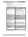
Crestron CNX-BF12 & CNX-BN12 Designer Function & Numeric Keypads Operations & Installation Guide This document was prepared and written by the Technical Documentation department at: Crestron Electronics, Inc. 15 Volvo Drive Rockleigh, NJ 07647 1-888-CRESTRON All brand names, product names and trademarks are the property of their respective owners. ©2006 Crestron Electronics, Inc. Crestron CNX-BF12 & CNX-BN12 Function & Numeric Keypads Contents Function & Numeric Keypads: CNX-BF12 & CNX-BN12 1 Introduction ............................................................................................................................... 1 Features and Functions ................................................................................................ 1 Specifications .............................................................................................................. 2 Physical Description.................................................................................................... 4 Industry Compliance ................................................................................................... 7 Setup .......................................................................................................................................... 8 Network Wiring........................................................................................................... 8 Identity Code ............................................................................................................... 8 Installation ................................................................................................................... 8 Hardware Hookup ..................................................................................................... 11 Button Replacement .................................................................................................. 11 Programming Software ............................................................................................................ 13 Earliest Version Software Requirements for the PC ................................................. 13 Programming with Crestron SystemBuilder.............................................................. 14 Programming with SIMPL Windows ........................................................................ 14 Programming with VisionTools Pro-e....................................................................... 16 Example Program ...................................................................................................... 17 Uploading and Upgrading........................................................................................................ 18 Establishing Communication..................................................................................... 18 Programs, Projects and Firmware.............................................................................. 18 Program Checks ........................................................................................................ 19 Operation ................................................................................................................................. 20 Problem Solving ...................................................................................................................... 21 Troubleshooting......................................................................................................... 21 Check Network Wiring.............................................................................................. 22 Reference Documents................................................................................................ 24 Further Inquiries ........................................................................................................ 24 Future Updates .......................................................................................................... 24 Software License Agreement................................................................................................... 25 Return and Warranty Policies .................................................................................................. 27 Merchandise Returns / Repair Service ...................................................................... 27 CRESTRON Limited Warranty................................................................................. 27 Operations & Installation Guide – DOC. 8185A Contents • i Crestron CNX-BF12 & CNX-BN12 Function & Numeric Keypads Function & Numeric Keypads: CNX-BF12 & CNX-BN12 Introduction Features and Functions • • • • • • • • Compatible with standard electrical gang boxes Ergonomic buttons are easy to read from any angle Backlit buttons are easy to locate Programmable LED indicators provide visual feedback Speaker provides audio feedback Temperature sensor reports to Cresnet® for HVAC monitoring1 Available in almond (A), black (B) and white (W)2 Additional source buttons for CNX-BF12 are provided, enabling custom source selection (refer to illustration on page 5) • Seamless Cresnet integration 1. The temperature sensor is not accurate when the backlight is on. 2. For example, a CNX-BN12B is a numeric keypad in black. NOTE: Keypads can also be mounted in multi-gang electrical boxes. Operations & Installation Guide – DOC. 8185A Function & Numeric Keypads: CNX-BF/BN12 • 1 Function & Numeric Keypads Crestron CNX-BF/BN12 Specifications Specifications for the CNX-BF12 & CNX-BN12 are listed in the following table. CNX-BF12 & CNX-BN12 Specifications SPECIFICATION Audio Audio Capacity WAV File Temperature Sensor Type Precision Accuracy Range Power Requirements Cresnet Power Usage Default NET ID Minimum 2-Series Control System Update File1, 2, 3 Environmental Temperature Humidity Enclosure DETAILS Built-in speaker, adjustable volume 101 WAV files maximum, ~56 seconds total time, 512 kB total memory 8-bit PCM, mono, 8 kHz sampling rate Linear, digital 0.18°F (0.1°C) 1.8°F (1.0°C) with all LEDs and backlight off 32° to 113°F (0° to 45°C) 3 Watts (0.125 Amps @ 24 Volts DC) 60 Version C2-2.004.CUZ or later 32° to 113°F (0° to 45°C) 10% to 90% RH (non-condensing) 1-gang mountable in a standard electrical box (Continued on following page) 2 • Function & Numeric Keypads: CNX-BF/BN12 Operations & Installation Guide – DOC. 8185A Crestron CNX-BF12 & CNX-BN12 Function & Numeric Keypads CNX-BF12 & CNX-BN12 Specifications (Continued) SPECIFICATION Dimensions (including faceplate) Height Width Depth Weight Available Models C2N-DBF/N12A C2N-DBF/N12B C2N-DBF/N12W Available Accessories B-G1-FP B-G2-FP B-G3-FP B-G1-FPAR B-G1-WPK DETAILS 4.77 in (12.10 cm) 2.92 in (7.40 cm) 1.54 in (3.91 cm) – without connector 2.60 oz (74 g) Almond Black White 1-Gang Designer Series and Standard Faceplates 2-Gang Designer Series and Standard Faceplates 3-Gang Designer Series and Standard Faceplates 1-Gang Architectural Series Faceplates Water Resistant Cover Kit 1. The latest software versions can be obtained from the Crestron® website. Refer to the NOTE following these footnotes. 2. Crestron 2-Series control systems include the AV2 and PRO2. Consult the latest Crestron Product Catalog for a complete list of 2-Series control systems. 3. Minimum Non 2-Series Control System Update Files: CEN/CN/TVAV Version 5.10.13V.UPZ or later CNMSX-AV/PRO Version 5.10.11X.UPZ or later CNRACKX/-DP Version 5.10.11W.UPZ or later ST-CP Version 4.01.04S.UPZ or later CNX update files are required for either CNMSX-AV/PRO or CNRACKX/-DP. Filenames for CNX update files have a UPZ extension, and ST-CP files are in one EXE or zipped UPZ file. To avoid program problems, make sure you are using the update file with the correct suffix letter (e.g., S, V, W, X). Operations & Installation Guide – DOC. 8185A Function & Numeric Keypads: CNX-BF/BN12 • 3 Function & Numeric Keypads Crestron CNX-BF/BN12 NOTE: Crestron software and any files on the website are for authorized Crestron dealers and Crestron Authorized Independent Programmers (CAIP) only. New users may be required to register to obtain access to certain areas of the site (including the FTP site). Physical Description This section provides information on the connections, controls and indicators available on your CNX-BF12 & CNX-BN12. CNX-BF12 & CNX-BN12 Physical View CNX-BF12 (White Color) 4 • Function & Numeric Keypads: CNX-BF/BN12 CNX-BN12 (Black Color) Operations & Installation Guide – DOC. 8185A Crestron CNX-BF12 & CNX-BN12 Function & Numeric Keypads CNX-BF12 & CNX-BN12 Overall Dimensions Side View with buttons installed 1.54 in (3.91 cm) 1.07 in (2.71 cm) Front View Back View 2.92 in (7.40 cm) 4.77 in (12.10 cm) 1 2 3 4 Connectors, Controls & Indicators # CONNECTORS1, CONTROLS & INDICATORS DESCRIPTION 1 Buttons 2 LED Indicators (12) Replaceable pre-labeled buttons, programmable; (18) Extra button caps supplied2 (1 per button, providing feedback, red) programmable and dimmable (Continued on following page) Operations & Installation Guide – DOC. 8185A Function & Numeric Keypads: CNX-BF/BN12 • 5 Function & Numeric Keypads Crestron CNX-BF/BN12 Connectors, Controls & Indicators (Continued) # CONNECTORS1, CONTROLS & INDICATORS DESCRIPTION 3 Speaker 4 NET1 Provides audio feedback, adjustable volume Four-position terminal block connector for data and power. Connects to Cresnet control network. An interface connector provided. Pin 1 (24) Power Pin 2 (Y) Data Pin 3 (Z) Data Pin 4 (G) Ground 1. Interface connector for NET port is provided with the unit. 2. CNX-BF12 only. Button Arrangements CNX-BN12 CNX-BF12 Standard Button Set CNX-BF12 Extra Button Set CLEAR ENTER CD FM ADAGIO AM DSS 1 2 JUKE SAT DSS 2 DVD FM 2 3 4 IPOD AUX IPOD 2 JUKE 2 MUSIC 5 6 ON-OFF MUTE SAT 2 SERVER SIRIUS 7 8 VOL SIRIUS 2 TUNER TV 9 0 VOL VCR XM XM 2 The keypads come fully assembled and each has 12 buttons with LED windows (refer to illustration on page 4). The CNX-BN12 has a CLEAR button, an ENTER button and numeric digit buttons 0 through 9. The CNX-BF12 has six source selector buttons, an ON-OFF button, a MUTE 6 • Function & Numeric Keypads: CNX-BF/BN12 Operations & Installation Guide – DOC. 8185A Crestron CNX-BF12 & CNX-BN12 Function & Numeric Keypads button, and device transport control and volume control buttons. A kit with additional source buttons for the CNX-BF12 is also provided (refer to illustration on page 6). Industry Compliance As of the date of manufacture the CNX-BF12 & CNX-BN12 have been tested and found to comply with specifications for CE marking and standards per EMC and Radiocommunications Compliance Labelling. NOTE: This device complies with part 15 of the FCC rules. Operation is subject to the following two conditions: (1) this device may not cause harmful interference and (2) this device must accept any interference received, including interference that may cause undesired operation. This equipment has been tested and found to comply with the limits for a Class B digital device, pursuant to part 15 of the FCC Rules. These limits are designed to provide reasonable protection against harmful interference in a residential installation. This equipment generates, uses and can radiate radio frequency energy and if not installed and used in accordance with the instructions, may cause harmful interference to radio communications. However, there is no guarantee that interference will not occur in a particular installation. If this equipment does cause harmful interference to radio or television reception, which can be determined by turning the equipment off and on, the user is encouraged to try to correct the interference by one or more of the following measures: Reorient or relocate the receiving antenna. Increase the separation between the equipment and receiver. Connect the equipment into an outlet on a circuit different from that to which the receiver is connected. Consult the dealer or an experienced radio/TV technician for help. Operations & Installation Guide – DOC. 8185A Function & Numeric Keypads: CNX-BF/BN12 • 7 Function & Numeric Keypads Crestron CNX-BF/BN12 Setup Network Wiring When wiring the network, consider the following: • Use Crestron Certified Wire. • Use Crestron power supplies for Crestron equipment. • Provide sufficient power to the system. CAUTION: Insufficient power can lead to unpredictable results or damage to the equipment. Please use the Crestron Power Calculator to help calculate how much power is needed for the system (http://www.crestron.com/calculators). • For larger networks, use a Cresnet Hub/Repeater (CNXHUB) to maintain signal quality. For more details, refer to “Check Network Wiring” on page 22. Identity Code The Net ID of the CNX-BF12 & CNX-BN12 has been factory set to 60. The Net IDs of multiple CNX-BF12 & CNX-BN12 devices in the same system must be unique. Net IDs are changed from a personal computer (PC) via the Crestron Toolbox™ (refer to “Establishing Communication” on page 18). When setting the Net ID, consider the following: • The Net ID of each unit must match an ID code specified in the SIMPL Windows program. • Each network device must have a unique Net ID. For more details, refer to the Crestron Toolbox help file. Installation The following tools/hardware are required for installation. • Cresnet network cable (sold separately) • Phillips screwdriver (not supplied) 8 • Function & Numeric Keypads: CNX-BF/BN12 Operations & Installation Guide – DOC. 8185A Crestron CNX-BF12 & CNX-BN12 Function & Numeric Keypads • Two 1-in. pan head Phillips screws (supplied) After the Cresnet network wiring has been installed and verified, use the following procedure to install the keypad in a standard, single-gang electrical box (refer to illustrations on page 10): 1. Turn Cresnet system power OFF. 2. Connect the Cresnet cable with supplied connector plug to the keypad’s Cresnet port and the other end to the control system. 3. Remove faceplate and divider from keypad. 4. Make sure button unit is oriented as marked with arrow at top and place it in the electrical box. CAUTION: Excess wire that is pinched between the keypad and electrical box could short out. Make sure that all excess wire is completely inside the electrical box and not between the box and the keypad. 5. Attach the keypad to the electrical box using the supplied two 1-in. pan head screws. 6. Attach faceplate and divider. 7. Turn Cresnet system power ON. Operations & Installation Guide – DOC. 8185A Function & Numeric Keypads: CNX-BF/BN12 • 9 Function & Numeric Keypads Crestron CNX-BF/BN12 Disassembly View Button unit Removable buttons Faceplate Single gang detent plate LED window Divider Installation View Single gang electrical box (2.5 in. depth recommended) Button unit 1 in. panhead 10 • Function & Numeric Keypads: CNX-BF/BN12 Operations & Installation Guide – DOC. 8185A Crestron CNX-BF12 & CNX-BN12 Function & Numeric Keypads Hardware Hookup Make the necessary connections as called out in the illustration that follows this paragraph. Refer to “Network Wiring” on page 8 before attaching the 4-position terminal block connector. Apply power after all connections have been made. When making connections to the CNX-BF12 & CNX-BN12, use Crestron power supplies. Hardware Connections for the CNX-BF12 & CNX-BN12 CRESNET: CONNECT TO THE CRESNET CONTROL NETWORK Button Replacement Replacing/changing the removable buttons in a keypad is a simple process. Refer to the illustrations on page 10 and the following procedures. 1. Remove faceplate from front of keypad. 2. If the keypad is installed in an electrical box, remove the two 1-inch securing screws, carefully pull the keypad from the electrical box, and disconnect the Cresnet cable. 3. Remove the divider. Operations & Installation Guide – DOC. 8185A Function & Numeric Keypads: CNX-BF/BN12 • 11 Function & Numeric Keypads Crestron CNX-BF/BN12 CAUTION: The removable buttons fit snugly on the rubber membrane and must be removed carefully to avoid pulling the membrane from the unit. Once the membrane is detached, you may be unable to reattach it. 4. While holding adjacent buttons in place, carefully pull the button(s) to be replaced from the rubber membrane. 5. Carefully press the replacement button(s) in place, make sure LED window(s) orientation is correct, and attach the divider using the four screws removed in step 2. 6. If applicable, reinstall the keypad in the electrical box. 12 • Function & Numeric Keypads: CNX-BF/BN12 Operations & Installation Guide – DOC. 8185A Crestron CNX-BF12 & CNX-BN12 Function & Numeric Keypads Programming Software Have a question or comment about Crestron software? Answers to frequently asked questions (FAQs) can be viewed in the Online Help section of the Crestron website. To post a question or view questions you have submitted to Crestron’s True Blue Support, log in at http://support.crestron.com. First-time users will need to establish a user account. Earliest Version Software Requirements for the PC NOTE: Crestron recommends that you use the latest software to take advantage of the most recently released features. The latest software is available from the Crestron website. Crestron has developed an assortment of Windows-based software tools to develop a Cresnet system. The following are the minimum recommended software versions for the PC: Software TASK REQUIRED SOFTWARE VERSION Program control system to operate CNX-BF12 & CNX-BN12. SIMPL Windows version 2.04.11 or later with SIMPL+ Cross Compiler version 1.1 or later and Library update 227 or later; Also requires Crestron Database version 15.9.8 or later. Crestron Toolbox 1.01.06 or later. Upload program and firmware. (Continued on following page) Operations & Installation Guide – DOC. 8185A Function & Numeric Keypads: CNX-BF/BN12 • 13 Function & Numeric Keypads Crestron CNX-BF/BN12 Software (Continued) TASK REQUIRED SOFTWARE VERSION Program with simple wizards for systems using a CNX-BF12 and/or CNX-BN12 (optional but recommended). Crestron SystemBuilder™ version 2.0 or later with SystemBuilder Templates version 2.0 or later. Refer to software release notes or Crestron website for other required Crestron software packages. Programming with Crestron SystemBuilder Crestron SystemBuilder is the easiest method of programming but does not offer as much flexibility as SIMPL Windows. For additional details, download SystemBuilder from the Crestron website and examine the extensive help file. Programming with SIMPL Windows NOTE: While SIMPL Windows can be used to program the CNX-BF12 & CNX-BN12, it is recommended to use SystemBuilder for configuring a system. SIMPL Windows is Crestron’s premier software for programming Crestron control systems. It is organized into two separate but equally important “Managers”. Configuration Manager Configuration Manager is the view where programmers “build” a Crestron control system by selecting hardware from the Device Library. • To incorporate the CNX-BF12 & CNX-BN12 into the system, drag the CNX-BF12 & CNX-BN12 from the Wired Keypad folder of the Device Library and drop it in the System Views. 14 • Function & Numeric Keypads: CNX-BF/BN12 Operations & Installation Guide – DOC. 8185A Crestron CNX-BF12 & CNX-BN12 Function & Numeric Keypads Locating the CNX-BF12 & CNX-BN12 in the Device Library • The system tree of the control system displays the device in the appropriate slot with a default Net ID as shown in the following illustration. C2Net Device, Slot 9 • Additional CNX-BF12 & CNX-BN12 devices are assigned different Net ID numbers as they are added. • If necessary, double click a device to open the “Device Settings” window and change the Net ID, as shown in the following figure. Operations & Installation Guide – DOC. 8185A Function & Numeric Keypads: CNX-BF/BN12 • 15 Function & Numeric Keypads Crestron CNX-BF/BN12 “CNX-BF12 & CNX-BN12 Device Settings” Window • The ID code specified in the SIMPL Windows program must match the Net ID of each unit. Program Manager Program Manager is the view where programmers “program” a Crestron control system by assigning signals to symbols. The symbol can be viewed by double clicking on the icon or dragging it into Detail View. Each signal in the symbol is described in the SIMPL Windows help file (F1). Programming with VisionTools® Pro-e To play WAV files, a CNX-BF12 or CNX-BN12 project must be created in VisionTools Pro-e, with WAV files and correct join numbers added to the project using Tools | Sound Manager. For more information, refer to the VisionTools Pro-e help file. NOTE: If you need to create WAV files, refer to Windows Help (Using Sound Recorder). NOTE: The keypad project allows you to add WAV files only. You cannot add pages or keypad buttons to the project. Join numbers assigned to a WAV file in VisionTools Pro-e begin at 20 because join numbers below 20 are already assigned to other keypad buttons or functions. Once the project is created, use File | Upload Project from the VisionTools Pro-e main menu to load it in the CNX-BF12 or CNX-BN12. For more information, refer to the VisionTools Pro-e help file. 16 • Function & Numeric Keypads: CNX-BF/BN12 Operations & Installation Guide – DOC. 8185A Crestron CNX-BF12 & CNX-BN12 Function & Numeric Keypads NOTE: This can be done after an identity code (NET ID) is assigned to the keypad or after installation (refer to “Identity Code” or “Installation” on page 8 for details). Example Program An example program for the CNX-BF12 & CNX-BN12 is available from the Crestron website (http://www.crestron.com/exampleprograms). Operations & Installation Guide – DOC. 8185A Function & Numeric Keypads: CNX-BF/BN12 • 17 Function & Numeric Keypads Crestron CNX-BF/BN12 Uploading and Upgrading Crestron recommends using the latest programming software and that each device contains the latest firmware to take advantage of the most recently released features. However, before attempting to upload or upgrade it is necessary to establish communication. Once communication has been established, files (for example, programs, projects or firmware) can be transferred to the control system (and/or device). Finally, program checks can be performed (such as changing the device ID) to ensure proper functioning. Establishing Communication Use Crestron Toolbox for communicating with the CNX-BF12 & CNX-BN12; refer to the Crestron Toolbox help file for details. There is a single method of communication: indirect serial communication. Indirect Serial Communication PC RUNNING CRESTRON TOOLBOX SERIAL, ETHERNET OR USB CONTROL SYSTEM CRESNET C2N-DBF/N12 • CNX-BF12 & CNX-BN12 connects to control system via Cresnet. • Establish communications between the PC and the control system as described in the latest version of the 2-Series Control Systems Reference Guide (Doc. 6256). Programs, Projects and Firmware Program, project or firmware files may be distributed from programmers to installers or from Crestron to dealers. Firmware upgrades are available from the Crestron website as new features are developed after product releases. One has the option to upload programs and projects via the programming software or to upload and upgrade via the Crestron Toolbox. For details on uploading and upgrading, refer to the SIMPL Windows help file, VisionTools Pro-e help file or the Crestron Toolbox help file. 18 • Function & Numeric Keypads: CNX-BF/BN12 Operations & Installation Guide – DOC. 8185A Crestron CNX-BF12 & CNX-BN12 Function & Numeric Keypads SIMPL Windows If a SIMPL Windows program is provided, it can be uploaded to the control system using SIMPL Windows or Crestron Toolbox. VisionTools Pro-e Upload the VisionTools Pro-e file to the keypad using VisionTools Pro-e or Crestron Toolbox. Firmware Check the Crestron website to find the latest firmware. (New users may be required to register to obtain access to certain areas of the site, including the FTP site.) • Upgrade CNX-BF12 & CNX-BN12 firmware via Crestron Toolbox. • Establish communications with the CNX-BF12 & CNX-BN12 and display the “System Info” window. • Select Functions | Firmware… to upgrade the CNX-BF12 & CNX-BN12 firmware. Program Checks For Cresnet connections, display the network device tree (Tools | Network Device Tree) to show all network devices connected to the control system. Right-click on the CNX-BF12 & CNX-BN12 to display actions that can be performed on the CNX-BF12 & CNX-BN12. Operations & Installation Guide – DOC. 8185A Function & Numeric Keypads: CNX-BF/BN12 • 19 Function & Numeric Keypads Crestron CNX-BF/BN12 Operation The CNX-BF12 serves as a source keypad. The CNX-BN12 can be used to expand the capabilities of the source keypad and is ideal for audio device functions such as selecting a particular CD track number or a certain CD from a CD changer. All buttons on the keypad are functionally identical and have light emitting diodes (LEDs) that serve as user feedback indicators. Each LED’s illumination (on/off) is independently addressable and is programmable using SIMPL Windows. In the program, the intensity level for all of the button LEDs can be set from 0 to 100%. 20 • Function & Numeric Keypads: CNX-BF/BN12 Operations & Installation Guide – DOC. 8185A Crestron CNX-BF12 & CNX-BN12 Function & Numeric Keypads Problem Solving Troubleshooting The following table provides corrective action for possible trouble situations. If further assistance is required, please contact a Crestron customer service representative. CNX-BF12 & CNX-BN12 Troubleshooting TROUBLE Keypad does not function. POSSIBLE CAUSE(S) CORRECTIVE ACTION Keypad is not communicating with the network. Use Crestron Toolbox to poll the network. Verify network connection to the device. Use Crestron power source. Verify connections. Keypad is not receiving power from a Crestron power source. Keypad is not receiving sufficient power. Keypad Net ID is not correct. Keypad Net ID is not set to match the net ID set in the SIMPL Windows program. Use the Crestron Power Calculator to help calculate how much power is needed for the system. In Toolbox, poll the network (F4) to verify Net ID. Verify Net ID setting in SIMPL Windows program. (Continued on following page) Operations & Installation Guide – DOC. 8185A Function & Numeric Keypads: CNX-BF/BN12 • 21 Function & Numeric Keypads Crestron CNX-BF/BN12 CNX-BF12 & CNX-BN12 Troubleshooting (Continued) TROUBLE Keypad does not function (continued). Button LED does not illuminate. Pressing button yields wrong result. No sound from speaker POSSIBLE CAUSE(S) CORRECTIVE ACTION Keypad Net ID is the same as another device’s Net ID. Feedback signal names incorrect in SIMPL Windows program. LED intensity set to 0 (zero). Keypad is mounted upside down. Keypad programmed incorrectly. Feedback audio signal is not present. Assign a different Net ID in SIMPL Windows and reset unit using Toolbox. Verify SIMPL Windows program for feedback signal names. Set intensity to desired level. Check keypad orientation. Check programming in SIMPL Windows. Verify VisionTools Pro-e program for feedback audio signals. Check Network Wiring Use the Right Wire Calculate Power In order to ensure optimum performance over the full range of your installation topology, Crestron Certified Wire and only Crestron Certified Wire may be used. Failure to do so may incur additional charges if support is required to identify performance deficiencies because of using improper wire. CAUTION: Use only Crestron power supplies for Crestron equipment. Failure to do so could cause equipment damage or void the Crestron warranty. CAUTION: Provide sufficient power to the system. Insufficient power can lead to unpredictable results or damage to the equipment. Please use 22 • Function & Numeric Keypads: CNX-BF/BN12 Operations & Installation Guide – DOC. 8185A Crestron CNX-BF12 & CNX-BN12 Function & Numeric Keypads the Crestron Power Calculator to help calculate how much power is needed for the system (http://www.crestron.com/calculators). When calculating the length of wire for a particular Cresnet run, the wire gauge and the Cresnet power usage of each network unit to be connected must be taken into consideration. Use Crestron Certified Wire only. If Cresnet units are to be daisy-chained on the run, the Cresnet power usage of each network unit to be daisy-chained must be added together to determine the Cresnet power usage of the entire chain. If the unit is home-run from a Crestron system power supply network port, the Cresnet power usage of that unit is the Cresnet power usage of the entire run. The wire gauge and the Cresnet power usage of the run should be used in the following equation to calculate the cable length value on the equation’s left side. Cable Length Equation 40,000 L< RxP Where: L = Length of run (or chain) in feet R = 6 Ohms (Crestron Certified Wire: 18 AWG (0.75 MM 2 )) or 1.6 Ohms (Cresnet HP: 12 AWG (4 MM 2 )) P = Cresnet power usage of entire run (or chain) Make sure the cable length value is less than the value calculated on the right side of the equation. For example, a Cresnet run using 18 AWG Crestron Certified Wire and drawing 20 watts should not have a length of run more than 333 feet. If Cresnet HP is used for the same run, its length could extend to 1250 feet. NOTE: All Crestron certified Cresnet wiring must consist of two twisted pairs. One twisted pair is the +24V conductor and the GND conductor and the other twisted pair is the Y conductor and the Z conductor. Strip and Tin Wire When daisy-chaining Cresnet units, strip the ends of the wires carefully to avoid nicking the conductors. Twist together the ends of the wires that share a pin on the network connector and tin the twisted connection. Apply solder only to the ends of the twisted wires. Avoid tinning too far up the wires or the end becomes brittle. Insert the tinned connection into the Cresnet connector and tighten the retaining screw. Repeat the procedure for the other three conductors. Add Hubs For larger networks (i.e., greater than 28 network devices), it may become necessary to add a Cresnet Hub/Repeater (CNXHUB) to Operations & Installation Guide – DOC. 8185A Function & Numeric Keypads: CNX-BF/BN12 • 23 Function & Numeric Keypads Crestron CNX-BF/BN12 maintain signal quality throughout the network. Also, for networks with lengthy cable runs it may be necessary to add a Hub/Repeater after only 20 devices. Reference Documents The latest version of all documents mentioned within the guide can be obtained from the Crestron website (http://www.crestron.com/manuals). This link will provide a list of product manuals arranged in alphabetical order by model number. List of Related Reference Documents DOCUMENT TITLE 2-Series Control Systems Reference Guide Further Inquiries If you cannot locate specific information or have questions after reviewing this guide, please take advantage of Crestron's award winning customer service team by calling the Crestron corporate headquarters at 1-888-CRESTRON [1-888-273-7876]. For assistance in your local time zone, refer to the Crestron website (http://www.crestron.com/) for a listing of Crestron worldwide offices. You can also log onto the online help section of the Crestron website to ask questions about Crestron products. First-time users will need to establish a user account to fully benefit from all available features. Future Updates As Crestron improves functions, adds new features and extends the capabilities of the CNX-BF12 & CNX-BN12, additional information may be made available as manual updates. These updates are solely electronic and serve as intermediary supplements prior to the release of a complete technical documentation revision. Check the Crestron website periodically for manual update availability and its relevance. Updates are identified as an “Addendum” in the Download column. 24 • Function & Numeric Keypads: CNX-BF/BN12 Operations & Installation Guide – DOC. 8185A Crestron CNX-BF12 & CNX-BN12 Function & Numeric Keypads Software License Agreement This License Agreement (“Agreement”) is a legal contract between you (either an individual or a single business entity) and Crestron Electronics, Inc. (“Crestron”) for software referenced in this guide, which includes computer software and, as applicable, associated media, printed materials, and “online” or electronic documentation (the “Software”). BY INSTALLING, COPYING, OR OTHERWISE USING THE SOFTWARE, YOU REPRESENT THAT YOU ARE AN AUTHORIZED DEALER OF CRESTRON PRODUCTS OR A CRESTRON AUTHORIZED INDEPENDENT PROGRAMMER AND YOU AGREE TO BE BOUND BY THE TERMS OF THIS AGREEMENT. IF YOU DO NOT AGREE TO THE TERMS OF THIS AGREEMENT, DO NOT INSTALL OR USE THE SOFTWARE. IF YOU HAVE PAID A FEE FOR THIS LICENSE AND DO NOT ACCEPT THE TERMS OF THIS AGREEMENT, CRESTRON WILL REFUND THE FEE TO YOU PROVIDED YOU (1) CLICK THE DO NOT ACCEPT BUTTON, (2) DO NOT INSTALL THE SOFTWARE AND (3) RETURN ALL SOFTWARE, MEDIA AND OTHER DOCUMENTATION AND MATERIALS PROVIDED WITH THE SOFTWARE TO CRESTRON AT: CRESTRON ELECTRONICS, INC., 15 VOLVO DRIVE, ROCKLEIGH, NEW JERSEY 07647, WITHIN 30 DAYS OF PAYMENT. LICENSE TERMS Crestron hereby grants You and You accept a nonexclusive, nontransferable license to use the Software (a) in machine readable object code together with the related explanatory written materials provided by Creston (b) on a central processing unit (“CPU”) owned or leased or otherwise controlled exclusively by You, and (c) only as authorized in this Agreement and the related explanatory files and written materials provided by Crestron. If this software requires payment for a license, you may make one backup copy of the Software, provided Your backup copy is not installed or used on any CPU. You may not transfer the rights of this Agreement to a backup copy unless the installed copy of the Software is destroyed or otherwise inoperable and You transfer all rights in the Software. You may not transfer the license granted pursuant to this Agreement or assign this Agreement without the express written consent of Crestron. If this software requires payment for a license, the total number of CPU’s on which all versions of the Software are installed may not exceed one per license fee (1) and no concurrent, server or network use of the Software (including any permitted back-up copies) is permitted, including but not limited to using the Software (a) either directly or through commands, data or instructions from or to another computer (b) for local, campus or wide area network, internet or web hosting services; or (c) pursuant to any rental, sharing or “service bureau” arrangement. The Software is designed as a software development and customization tool. As such Crestron cannot and does not guarantee any results of use of the Software or that the Software will operate error free and You acknowledge that any development that You perform using the Software or Host Application is done entirely at Your own risk. The Software is licensed and not sold. Crestron retains ownership of the Software and all copies of the Software and reserves all rights not expressly granted in writing. OTHER LIMITATIONS You must be an Authorized Dealer of Crestron products or a Crestron Authorized Independent Programmer to install or use the Software. If Your status as a Crestron Authorized Dealer or Crestron Authorized Independent Programmer is terminated, Your license is also terminated. You may not rent, lease, lend, sublicense, distribute or otherwise transfer or assign any interest in or to the Software. You may not reverse engineer, decompile, or disassemble the Software. You agree that the Software will not be shipped, transferred or exported into any country or used in any manner prohibited by the United States Export Administration Act or any other export laws, restrictions or regulations (“Export Laws”). By downloading or installing the Software You (a) are certifying that You are not a national of Cuba, Iran, Iraq, Libya, North Korea, Sudan, or Syria or any country to which the United States embargoes goods (b) are certifying that You are not otherwise prohibited from receiving the Software and (c) You agree to comply with the Export Laws. If any part of this Agreement is found void and unenforceable, it will not affect the validity of the balance of the Agreement, which shall remain valid and enforceable according to its terms. This Agreement may only be modified by a writing signed by an authorized officer of Crestron. Updates may be licensed to You by Crestron with additional or different terms. This is the entire agreement between Crestron and You relating to the Software and it supersedes any prior representations, discussions, undertakings, communications or advertising relating to the Software. The failure of either party to enforce any right or take any action in the event of a breach hereunder shall constitute a waiver unless expressly acknowledged and set forth in writing by the party alleged to have provided such waiver. Operations & Installation Guide – DOC. 8185A Function & Numeric Keypads: CNX-BF/BN12 • 25 Function & Numeric Keypads Crestron CNX-BF/BN12 If You are a business or organization, You agree that upon request from Crestron or its authorized agent, You will within thirty (30) days fully document and certify that use of any and all Software at the time of the request is in conformity with Your valid licenses from Crestron of its authorized agent. Without prejudice to any other rights, Crestron may terminate this Agreement immediately upon notice if you fail to comply with the terms and conditions of this Agreement. In such event, you must destroy all copies of the Software and all of its component parts. PROPRIETARY RIGHTS Copyright. All title and copyrights in and to the Software (including, without limitation, any images, photographs, animations, video, audio, music, text, and “applets” incorporated into the Software), the accompanying media and printed materials, and any copies of the Software are owned by Crestron or its suppliers. The Software is protected by copyright laws and international treaty provisions. Therefore, you must treat the Software like any other copyrighted material, subject to the provisions of this Agreement. Submissions. Should you decide to transmit to Crestron’s website by any means or by any media any materials or other information (including, without limitation, ideas, concepts or techniques for new or improved services and products), whether as information, feedback, data, questions, comments, suggestions or the like, you agree such submissions are unrestricted and shall be deemed non-confidential and you automatically grant Crestron and its assigns a non-exclusive, royalty-tree, worldwide, perpetual, irrevocable license, with the right to sublicense, to use, copy, transmit, distribute, create derivative works of, display and perform the same. Trademarks. CRESTRON and the Swirl Logo are registered trademarks of Crestron Electronics, Inc. You shall not remove or conceal any trademark or proprietary notice of Crestron from the Software including any back-up copy. GOVERNING LAW This Agreement shall be governed by the laws of the State of New Jersey, without regard to conflicts of laws principles. Any disputes between the parties to the Agreement shall be brought in the state courts in Bergen County, New Jersey or the federal courts located in the District of New Jersey. The United Nations Convention on Contracts for the International Sale of Goods, shall not apply to this Agreement. CRESTRON LIMITED WARRANTY CRESTRON warrants that: (a) the Software will perform substantially in accordance with the published specifications for a period of ninety (90) days from the date of receipt, and (b) that any hardware accompanying the Software will be subject to its own limited warranty as stated in its accompanying written material. Crestron shall, at its option, repair or replace or refund the license fee for any Software found defective by Crestron if notified by you within the warranty period. The foregoing remedy shall be your exclusive remedy for any claim or loss arising from the Software. CRESTRON shall not be liable to honor warranty terms if the product has been used in any application other than that for which it was intended, or if it as been subjected to misuse, accidental damage, modification, or improper installation procedures. Furthermore, this warranty does not cover any product that has had the serial number or license code altered, defaced, improperly obtained, or removed. Notwithstanding any agreement to maintain or correct errors or defects Crestron, shall have no obligation to service or correct any error or defect that is not reproducible by Crestron or is deemed in Crestron’s reasonable discretion to have resulted from (1) accident; unusual stress; neglect; misuse; failure of electric power, operation of the Software with other media not meeting or not maintained in accordance with the manufacturer’s specifications; or causes other than ordinary use; (2) improper installation by anyone other than Crestron or its authorized agents of the Software that deviates from any operating procedures established by Crestron in the material and files provided to You by Crestron or its authorized agent; (3) use of the Software on unauthorized hardware; or (4) modification of, alteration of, or additions to the Software undertaken by persons other than Crestron or Crestron’s authorized agents. ANY LIABILITY OF CRESTRON FOR A DEFECTIVE COPY OF THE SOFTWARE WILL BE LIMITED EXCLUSIVELY TO REPAIR OR REPLACEMENT OF YOUR COPY OF THE SOFTWARE WITH ANOTHER COPY OR REFUND OF THE INITIAL LICENSE FEE CRESTRON RECEIVED FROM YOU FOR THE DEFECTIVE COPY OF THE PRODUCT. THIS WARRANTY SHALL BE THE SOLE AND EXCLUSIVE REMEDY TO YOU. IN NO EVENT SHALL CRESTRON BE LIABLE FOR INCIDENTAL, CONSEQUENTIAL, SPECIAL OR PUNITIVE DAMAGES OF ANY KIND (PROPERTY OR ECONOMIC DAMAGES INCLUSIVE), EVEN IF A CRESTRON REPRESENTATIVE HAS BEEN ADVISED OF THE POSSIBILITY OF SUCH DAMAGES OR OF ANY CLAIM BY ANY THIRD PARTY. CRESTRON MAKES NO WARRANTIES, EXPRESS OR IMPLIED, AS TO TITLE OR INFRINGEMENT OF THIRD-PARTY RIGHTS, MERCHANTABILITY OR FITNESS FOR ANY PARTICULAR PURPOSE, OR ANY OTHER WARRANTIES, NOR AUTHORIZES ANY OTHER PARTY TO OFFER ANY WARRANTIES, INCLUDING WARRANTIES OF MERCHANTABILITY FOR THIS PRODUCT. THIS WARRANTY STATEMENT SUPERSEDES ALL PREVIOUS WARRANTIES. 26 • Function & Numeric Keypads: CNX-BF/BN12 Operations & Installation Guide – DOC. 8185A Crestron CNX-BF12 & CNX-BN12 Function & Numeric Keypads Return and Warranty Policies Merchandise Returns / Repair Service 1. No merchandise may be returned for credit, exchange or service without prior authorization from CRESTRON. To obtain warranty service for CRESTRON products, contact an authorized CRESTRON dealer. Only authorized CRESTRON dealers may contact the factory and request an RMA (Return Merchandise Authorization) number. Enclose a note specifying the nature of the problem, name and phone number of contact person, RMA number and return address. 2. Products may be returned for credit, exchange or service with a CRESTRON Return Merchandise Authorization (RMA) number. Authorized returns must be shipped freight prepaid to CRESTRON, 6 Volvo Drive, Rockleigh, N.J. or its authorized subsidiaries, with RMA number clearly marked on the outside of all cartons. Shipments arriving freight collect or without an RMA number shall be subject to refusal. CRESTRON reserves the right in its sole and absolute discretion to charge a 15% restocking fee plus shipping costs on any products returned with an RMA. 3. Return freight charges following repair of items under warranty shall be paid by CRESTRON, shipping by standard ground carrier. In the event repairs are found to be non-warranty, return freight costs shall be paid by the purchaser. CRESTRON Limited Warranty CRESTRON ELECTRONICS, Inc. warrants its products to be free from manufacturing defects in materials and workmanship under normal use for a period of three (3) years from the date of purchase from CRESTRON, with the following exceptions: disk drives and any other moving or rotating mechanical parts, pan/tilt heads and power supplies are covered for a period of one (1) year; touchscreen display and overlay components are covered for 90 days; batteries and incandescent lamps are not covered. This warranty extends to products purchased directly from CRESTRON or an authorized CRESTRON dealer. Purchasers should inquire of the dealer regarding the nature and extent of the dealer's warranty, if any. CRESTRON shall not be liable to honor the terms of this warranty if the product has been used in any application other than that for which it was intended or if it has been subjected to misuse, accidental damage, modification or improper installation procedures. Furthermore, this warranty does not cover any product that has had the serial number altered, defaced or removed. This warranty shall be the sole and exclusive remedy to the original purchaser. In no event shall CRESTRON be liable for incidental or consequential damages of any kind (property or economic damages inclusive) arising from the sale or use of this equipment. CRESTRON is not liable for any claim made by a third party or made by the purchaser for a third party. CRESTRON shall, at its option, repair or replace any product found defective, without charge for parts or labor. Repaired or replaced equipment and parts supplied under this warranty shall be covered only by the unexpired portion of the warranty. Except as expressly set forth in this warranty, CRESTRON makes no other warranties, expressed or implied, nor authorizes any other party to offer any warranty, including any implied warranties of merchantability or fitness for a particular purpose. Any implied warranties that may be imposed by law are limited to the terms of this limited warranty. This warranty statement supersedes all previous warranties. Trademark Information All brand names, product names and trademarks are the sole property of their respective owners. Windows is a registered trademark of Microsoft Corporation. Windows95/98/Me/XP and WindowsNT/2000 are trademarks of Microsoft Corporation. Operations & Installation Guide – DOC. 8185A Function & Numeric Keypads: CNX-BF/BN12 • 27 Crestron Electronics, Inc. 15 Volvo Drive Rockleigh, NJ 07647 Tel: 888.CRESTRON Fax: 201.767.7576 www.crestron.com Operations & Installation Guide – DOC. 8185A (2002201) 12.06 Specifications subject to change without notice.